Document Outline
- Front Page
- Ordering Information
- Specifications
- Operation
- Engineering Data
- Dimensions
- Precautions
- Contacting Omron
E2EZ
E2EZ
2
Description
Part number
Mounting brackets
Fits M18 size sensors
Y92E-B18
Fits M30 size sensors
Y92E-B30
Protective covers
Fits M18 size sensors
Y92E-E18-2
for shielded sensors
Fits M30 size sensors
Y92E-E30-2
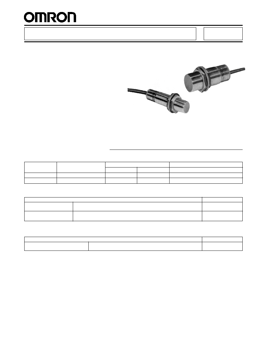
Sensor Immune to Metal Chip Accumulation,
Ideal for Machine Tool Applications
s
Detects work piece properly even when
aluminum or iron chips collect on the
sensing head during drilling or cutting
s
Housing resists water splash and oil
contamination to IEC IP67 standards
s
Oil-tight cable and operation indicator
are standard
s
Shielded for flush mounting in metal
s
Prewired with 2 meters (6.56 ft) of cable
Chip Immune Inductive Prox
E2EZ
Ordering Information
Sensing
Detecting
DC Output
AC Output
head
distance
NPN-NO
PNP-NO
NO
M18
4 mm (0.16 in)
E2EZ-X4C1
E2EZ-X4B1
E2EZ-X4Y1
M30
8 mm (0.32 in)
E2EZ-X8C1
E2EZ-X8B1
E2EZ-X8Y1
s
SENSORS
s
ACCESSORIES
Description
Part number
Mounting hardware including one
Fits M18 size sensors (supplied with each sensor)
M18-MHWS
pair of metal nuts and washers
Fits M30 size sensors (supplied with each sensor)
M30-MHWS
s
REPLACEMENT PARTS
E2EZ
E2EZ
3
Part number
E2EZ-X4
s s
E2EZ-X8
s s
Sensor type
Inductive
Body
Size
M18
M30
Type
Shielded
Supply voltage
100 to 240 VAC, 50/60 Hz or 10 to 30 VDC, max. ripple 10% peak-to-peak
Current consumption
AC: 2 mA max. at 100 VAC, 3 mA max. at 200 VAC
DC: 15 mA max.
Detectable object type
Ferrous metals
Effective detecting distance
4 mm
�
10%
8 mm
�
10%
(with standard target)
(0.16 in)
(0.32 in)
Usable detecting range
0 to 3.2 mm
0 to 6.5 mm
(with standard target)
(0 to 0.13 in)
(0 to 0.26 in)
Standard target size
30 x 30 x 1 mm
54 x 54 x 1 mm
aluminum (L x W x H)
(1.18 x 1.18 x 0.04 in)
(2.13 x 2.13 x 0.04 in)
Differential travel
20% max. of effective detecting distance
Control
AC
Type
SCR-NO (E2EZ-X
s
Y1)
output
solid-
Max. load
10 to 200 mA
state
Max. ON-state
See graph in Engineering Data section
voltage drop
Max. OFF-state
See graph in Engineering Data section
leakage current
DC
Type
NPN-NO (E2EZ-X
s
C1)
solid-
PNP-NO (E2EZ-X
s
B1)
state
Max. load
100 mA max. at 12 VDC, 200 mA max. at 24 VDC
Max. ON-state
2 VDC
voltage drop
Response
AC
5 Hz
5 Hz
frequency
DC
12 Hz
8 Hz
Circuit protection
AC
Not provided
DC
Output short circuit, surge voltage, reverse polarity
Indicators
Target present (red LED)
Materials
Housing
Nickel-plated brass
Sensing face
ABS
Mounting
Two M18 nuts included.
Two M30 nuts included.
Bracket Y92E-B18 optional.
Bracket Y92E-B30 optional.
Connections
AC
2-conductor cable, 2 m (6.56 ft) length
DC
3-conductor cable, 2 m (6.56 ft) length
Weight
170 g (6.0 oz.)
270 g (9.5 oz.)
Enclosure
UL
--
ratings
NEMA
1, 4X, 6, 12, 13
IEC 144
IP67
Approvals
UL
--
CSA
--
Ambient operating temperature
0
�
to 50
�
C (32
�
to 122
�
F)
Vibration
10 to 55 Hz, 1.5 mm (0.06 in) double amplitude for 2 hours each in X, Y, and Z directions
Shock
Approx. 100 G's, 10 times each in X, Y, and Z directions
Specifications
E2EZ
E2EZ
4
s
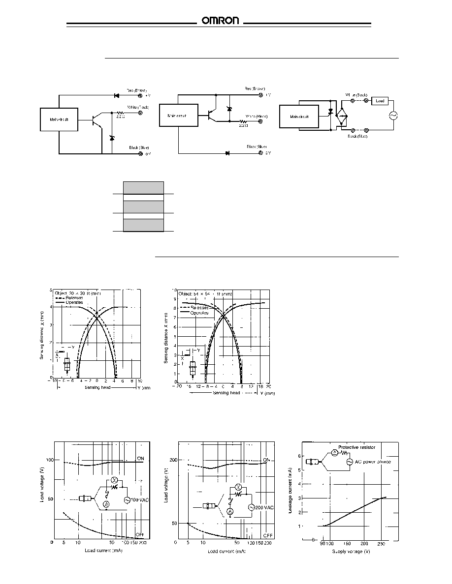
OUTPUT CIRCUIT DIAGRAMS AND CONNECTIONS
NPN Output Type
s
TIMING CHARTS
Engineering Data
Object
Present
Absent
Load
Operates
Releases
Operation
ON
indicator
OFF
E2EZ-X4
s s
E2EZ-X8
s s
s
OPERATING RANGE
Note: IEC colors are shown in parentheses.
PNP Output Type
SCR Output Type
Operation
Residual Load Voltage Characteristics
OFF-State Leakage Current
100 VAC
200 VAC
s
ELECTRICAL REQUIREMENTS FOR AC SENSORS (E2EZ-X
s
Y1)
E2EZ
E2EZ
5
Precautions
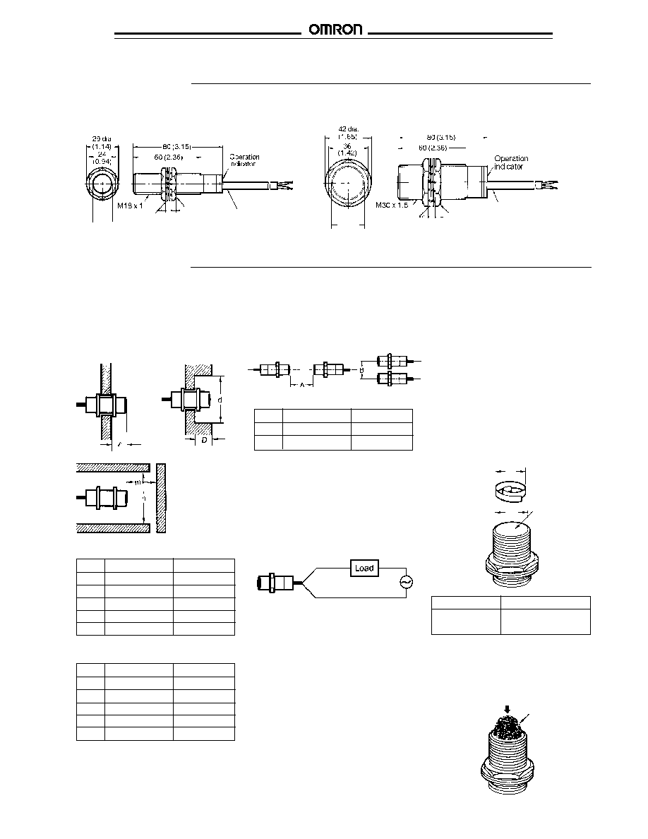
Dimensions
E2EZ-X4
s
1
E2EZ-X8
s
1
Unit: mm (inch)
18.5
(0.73) dia.
Two toothed
washers
4
(0.16)
4
(0.16)
Two clamping
nuts
2 m (6.56 ft) cable
6 (0.24) OD
30.5
(1.2) dia.
Two toothed
washers
5
(0.20)
5
(0.20)
Two clamping
nuts
2 m (6.56 ft) cable
6 (0.24) OD
s
EFFECTS OF
SURROUNDING METALS
When mounting a proximity sensor flush
with a metallic panel, provide the
minimum distance shown. This prevents
the sensor from being affected by
metallic objects other than the target.
Model E2EZ-X4
s s
E2EZ-X8
s s
l
0
0
d
18 mm (0.71 in)
30 mm (1.18 in)
D
0
0
m
16 mm (0.63 in)
32 mm (1.26 in)
n
27 mm (1.06 in)
45 mm (1.77 in)
For Iron
For Aluminum
Model E2EZ-X4
s s
E2EZ-X8
s s
l
5 mm (0.20 in)
10 mm (0.39 in)
d
40 mm (1.57 in)
70 mm (2.76 in)
D
5 mm (0.20 in)
10 mm (0.39 in)
m
16 mm (0.63 in)
32 mm (1.26 in)
n
54 mm (2.13 in)
90 mm (3.54 in)
s
MUTUAL INTERFERENCE
To prevent mutual interference between
two sensors mounted opposite or parallel
to each other, be sure to space the two
sensors at a distance greater than that
shown here.
Model E2EZ-X4
s s
E2EZ-X8
s s
A
4 cm (1.57 in)
6 cm (2.36 in)
B
5 cm (1.97 in)
10 cm (3.94 in)
s
IMMUNITY AGAINST METAL
CHIPS
Even if aluminum or iron chips collect on
the sensing head, no signal is produced
indicating the detection of metal chips.
However, the detection signal may be
produced under either of the following two
conditions. If a signal is produced from
metal chips on the sensing head, remove
the chips from the sensing head.
Large Chips
If the size (d) of the chips collected on the
sensing head is greater than or equal to
2/3 of the size (D) of the sensing surface.
d
2/3 x D
Model
Sensing surface (D)
E2EZ-X4
s
1
16 mm (0.63 in)
E2EZ-X8
s
1
28 mm (1.10 in)
D
Sensing surface
d
Compressed Chips
If chips are pressed against the sensing
surface by an external force the sensor
will detect the chips.
Chips
Compacting
pressure
s
CONNECTION TO AC
POWER SOURCE
Be sure to connect the proximity sensor to
the power source through a load. Direct
connection may damage the sensor.

E2EZ
E2EZ
OMRON ELECTRONICS LLC
OMRON CANADA, INC.
One East Commerce Drive
885 Milner Avenue
Schaumburg, IL 60173
Scarborough, Ontario M1B 5V8
1-800-55-OMRON
416-286-6465
Cat. No. CEDSAX4
11/01
Specifications subject to change without notice.
Printed in the U.S.A.
OMRON ON-LINE
Global - http://www.omron.com
USA - http://www.omron.com/oei
Canada - http://www.omron.com/oci