 | –≠–ª–µ–∫—Ç—Ä–æ–Ω–Ω—ã–π –∫–æ–º–ø–æ–Ω–µ–Ω—Ç: E2J | –°–∫–∞—á–∞—Ç—å:  PDF PDF  ZIP ZIP |
Document Outline
- First Page
- Ordering Information
- Specifications
- Operation
- Engineering Data
- Dimensions
- Nomenclature
- Installation
- Precautions
- Contacting Omron

R
Adjustable Flat Capacitive Prox
E2J
Thin Sensor with Separate Amplifier
Ideal for Robotic Grippers, Wafers,
LCD, and PDP Detection
Applications
H
Adjustable sensitivity on separate
amplifier
H
Flat sensing head is only 5.5 mm thick
H
Robotic cable takes continuous flexing
H
Dual LED indicator for power and output
Ordering Information
J
SENSORS
Type
Sensing distance
Part number
Flat
Unshielded
Min.
sensing
distance
Sensing range
0 to 10 mm
4 to 10 mm
Adjustable
range
Max. sensing distance
E2J-W10MA
Adjustable range
Sensing range
Max. sensing distance
8 to 20 mm
0 to 20 mm
Min.
sensing
distance
E2J-W20MA
J
AMPLIFIER UNIT
Type
Output configuration
Part number
DC 3-wire
NPN open collector, switch selectable NO or NC operation
E2J-JC4A

E2J
E2J
2
J
ACCESSORIES (SOLD SEPARATELY)
Description
Part number
Extension robotic
M8-screw-mounting, vibration-proof, 4 conductors
1 m (3.3 ft) length
XS3W-M421-401-R
Extension robotic
cables
M8 screw mounting, vibration proof, 4 conductors
2 m (6.6 ft) length
XS3W-M421-402-R
Connector dust
Red PVC, does not seal to IP67
For amplifier
XS3Z-13
Connector dust
covers
Red PVC, does not seal to IP67
For sensing head
XS3Z-15
Specifications
J
RATINGS/CHARACTERISTICS
Sensors
Part number
E2J-W10MA
E2J-W20MA
Sensing distance adjustable range
4 to 10 mm (0.16 to 0.39 in)
8 to 20 mm (0.32 to 0.79 in)
Sensing range
0 to 10 mm (0 to 0.39 in)
0 to 20 mm (0 to 0.79 in)
Standard sensing target
50 x 50 mm grounded metal (t = 1 mm)
Sensing target
Metallic and non--metallic objects
Differential travel
15% max. of sensing distance
Response frequency
70 kHz max.
Ambient temperature
Operating
--10∞C to 55∞C (14∞F to 131∞F)
Ambient humidity
Operating
35% to 95%
Enclosure rating
IEC IP66
Vibration resistance
Malfunction
10 to 500 Hz, 2.0-mm double amplitude or 150 m/s
2
(approx. 15G) for 2 hrs
each in X, Y, and Z directions
Shock resistance
Malfunction
500 m/s
2
(approx. 50G) for 3 times each in X, Y, and Z directions
Weight
Approx. 30 g (1.05 oz)
Approx. 40 g (1.4 oz)
Case material
ABS resin
Amplifier Unit
Part number
E2J-JC4A
Supply voltage
24 VDC±10%, ripple (p-p): 10% max.
Current consumption
30 mA max.
Control output
100 mA max., NPN open collector
Output residual voltage
1 V max.
Circuit protection
Reverse connection, load short-circuit, and surge absorption
Ambient temperature
Operating
--10∞C to 55∞C (14∞F to 131∞F)
Ambient humidity
Operating
35% to 85%
Temperature influence
(Sensor Head and Amplifier Unit)
±25% max. of sensing distance at 23∞C (73.4 ∞F) in temperature range of 0∞C
to 40∞C (32∞F to 104∞F)
Voltage influence
±1% max. of sensing distance in rated voltage range of ±20%
Insulation resistance
50 M (at 500 VDC) between current carry parts and case
Dielectric strength
1,000 VAC (50/60 Hz) for 1 min between current carry parts and case
Vibration resistance
Malfunction
10 to 150 Hz, 1.5-mm double amplitude or 150 m/s
2
(approx. 15G) for 2 hrs
each in X, Y, and Z directions
Shock resistance
Malfunction
300 m/s
2
(approx. 30G) for 3 times each in X, Y, and Z directions
Enclosure rating
IEC IP50
Weight
Approx. 60 g (21 oz)
Case material
ABS
E2J
E2J
3
Operation
J
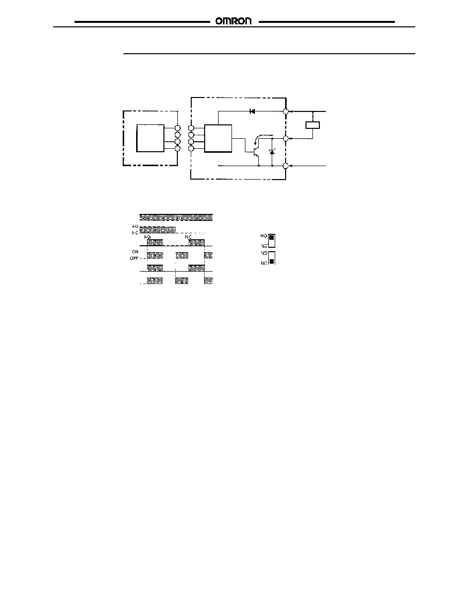
OUTPUT CIRCUIT
Main
circuit
Main
circuit
Sensor Head
Amplifier Unit
Load
Brown
Black
Output
Blue
24 VDC
0 V
100 mA max.
J
OPERATING CHARTS
Power indicator
Sensor Head
sensing indicator
Amplifier Unit
operation indicator
Sensing object
ON
OFF
Yes
No
ON
OFF
ON
OFF
Mode selector
Output transistor
The output transistor is ON when the
sensing object is detected.
The output transistor is ON when the
sensing object is not detected.
E2J
E2J
4
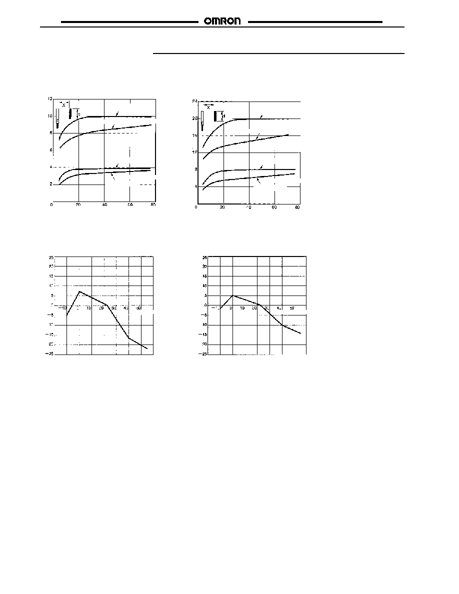
Engineering Data
J
SENSING DISTANCE VS. SENSING OBJECT (IRON)
E2J-W10MA
E2J-W20MA
Se
n
s
i
n
g
d
i
s
t
a
n
c
e
X
(mm)
Se
n
s
i
n
g
d
i
s
t
a
n
c
e
X
(mm)
Side length of target d (mm)
Side length of target d (mm)
Grounded
Non-grounded (Sensitivity adjuster: Max.)
Grounded
Non-grounded
(Sensitivity adjuster: Min.)
Grounded
Non-grounded
(Sensitivity adjuster: Max.)
Grounded
Non-grounded
(Sensitivity adjuster: Min.)
J
INFLUENCE OF AMBIENT TEMPERATURE
E2J-W10MA
E2J-W20MA
V
a
r
i
at
ion
r
at
e
(
%)
V
a
r
i
at
ion
r
at
e
(
%)
Temperature (∞C)
Temperature (∞C)

E2J
E2J
5
J
SENSING DISTANCE OF SENSING OBJECTS
E2J-W10MA
E2J-W20MA
Ma
xi
mu
m
s
e
n
s
i
n
g
d
i
s
t
a
n
c
e
(mm)
Grounded
iron
Non-grounded
iron
Acryl
Glass
Silicon
wafer
Grounded
iron
Non-grounded
iron
Acryl
Glass
Silicon
wafer
50 x 50 mm
t=1 mm
50 x 50 mm
t=1 mm
50 x 50 mm
t=10 mm
150 x 180 mm
t=1.2 mm
50 x 50 mm
t=1 mm
50 x 50 mm
t=1 mm
50 x 50 mm
t=10 mm
150 x 180 mm
t=1.2 mm
Ma
xi
mu
m
s
e
n
s
i
n
g
d
i
s
t
a
n
c
e
(mm)
2 inches
2 inches
J
SENSING RANGES
E2J-W10MA
E2J-W20MA
Sensing
object
Sensing
object
Grounded iron (50x50x1 mm)
Glass
Glass
V
e
rt
i
c
a
l
d
i
re
ct
i
o
n
X
(mm)
LED side of
Sensor
Head
Non-LED side
of Sensor
Head
Horizontal direction Y (mm)
LED side of
Sensor
Head
Non-LEDside
of Sensor
Head
Horizontal direction Y (mm)
Grounded iron (50x50x1 mm)
V
e
rt
i
c
a
l
d
i
re
ct
i
o
n
X
(mm)
Dimensions
Unit: mm (inch)
J
SENSORS
E2J-W10MA
Sensing side
Two, 3.2 dia.
Sensing indicator (red)
4-dia. (40/0.08 dia.) robot cable
with four conductors; standard
length: 1 m
Mounting Holes
9 dia.
Two, M3
30
(1.18)
8.5 (.33)
4.5 (.18)
3 (.12)
8 (.31)
140.1
15.5
(.61)
20 (.79)
3.1
(.12)
15.7
(.62)
5.5
.22
0.2
(.01)
2.2
(.09)
140.1
(.55.004)
(.55.004)

E2J
E2J
6
Unit: mm (inch)
E2J-W20MA
Sensing side
Two, 3.2 dia.
Sensing indicator (red)
4-dia. (40/0.08 dia.) robot cable
with four conductors; standard
length: 1 m
9 dia.
Mounting Holes
Two, M3
40
(1.57)
8.5
(.33)
20.5
(0.81)
25
(0.98)
30
(1.18)
5.5
(.22)
0.2
(.01)
24
0.1
(.95
.004)
4.5 (.18)
3 (.12)
2.2
(.09)
16
(.62)
J
AMPLIFIER UNIT
E2J-JC4A
M8 connector
Operation indicator
Power indicator
4-dia. (18 x 0.12 dia.)
vinyl-insulated round cord
with three conductors;
standard length: 2 m
Mounting Bracket
Two, mounting holes
Two,
3.2 dia.
Four, 1.7 radius
59.1
(2.33)
8.3
(.33)
8.3 (.33)
3.9
(.15)
4
(.16)
13
(.51)
22.5
(.89)
16
(.63)
4
(.16)
11.5
(.45)
12.2
(.48)
3.4
(.13)
3.4
(.13)
2
(.08)
29.3
(1.2)
15.9
(.63)
3.4
(.13)
9
(.35)
9
(.35)
J
CONNECTOR DUST COVERS
XS3Z-13
XS3Z-15
XS3Z-13
XS3Z-15
Note: Although the XS3Z Dust Covers protect the E2J from dust, they do not satisfy IP67. When attaching the Dust Cover, be sure to fully
insert the connector into the Dust Cover.
E2J
E2J
7
J
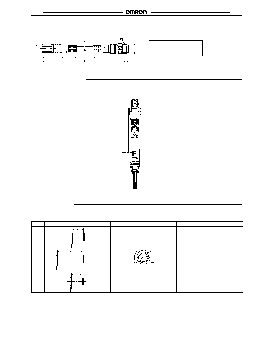
EXTENSION ROBOTIC CABLES
Socket
9 dia.
4 dia.
10 dia.
Plug
Part number
L
XS3W-M421-401-R
XS3W-M421-402-R
1 m
2 m
Nomenclature
J
AMPLIFIER UNIT
Power indicator (green)
Operation mode selector
Operation indicator (orange)
Sensitivity indicator
Sensitivity adjuster
Installation
J
ADJUSTMENT PROCEDURE
Step
Sensing
Sensitivity adjuster
Adjustment
1
Sensing object
---
Obtain the sensing distance X from the
set distance S divided by 0.75. (See
note). Determine S so that X will be less
than the maximum sensing distance.
2
Sensing object
Locate the Sensor so that the distance
between the Sensor and sensing object
is X. Turn the sensitivity adjuster
clockwise until the red sensing indicator
of the Sensor Head is lit.
3
Sensing object
---
Return the Sensor to the previous
position so that the distance between
the Sensor and sensing object is S.
Note: 1. If the ambient temperature is beyond 0∞C to 40∞C, divide by 0.7 to obtain sensing distance.
2. After completing sensitivity adjustment, mount the provided cover on the Amplifier Unit to prevent misoperation.
3. The maximum sensing distance will drop depending on the dimensions and material of the sensing object. Refer to Engineering
Data.

E2J
E2J
8
Precautions
J
SAFETY PRECAUTIONS
∑
Do not use the sensor in an environment where it will be
exposed to inflammable or explosive gases.
∑
Do not attempt to disassemble, repair, or modify the
Sensor.
∑
Be careful not to connect the power source with the
polarities in reverse.
∑
Do not short-circuit the loads.
∑
Do not use the Sensor at voltages exceeding the rated
voltage.
J
HANDLING
∑
Do not use the Sensor outdoors.
∑
Do not wire the Sensor alongside a high-tension or power
line.
∑
Do not use portable telephones or transceivers near the
Sensor. Be sure to ground the Mounting Brackets.
∑
Do not use the Sensor in an environment where it will be
exposed to chemicals, particularly chemical solutions or
oxidizing acids.
J
TIGHTENING TORQUE
Be sure that the tightening torque does not exceed the following
value.
A
Location
Torque
A
0.54N S m {5.5 kgf S cm} max.
J
EFFECTS OF SURROUNDING METAL
Before mounting the sensor, be sure that the sensor will be
separated from surrounding objects as shown in the following
illustration.
Sensing side
Sensor
Sensor
Sensing side
Metal object
Be sure to
ground the
metal object.
Metal object
Be sure to
ground the
metal object.
Dimension
E2J-W10MA
E2J-W20MA
B
10 mm (0.39 in)
20 mm (0.79 in)
C
20 mm (0.79 in)
40 mm (1.57 in)
J
EFFECTS OF STATIC ELECTRICITY
Be sure to discharge static electricity before detecting objects
that are greatly affected by static electricity.
J
MUTUAL INTERFERENCE
When mounting more than two sensors face to face or side by
side, ensure that the minimum distances given in the following
table are maintained.
Distance
E2J-W10MA
E2J-W20MA
E
20 mm (0.79 in)
70 mm (2.76 in)
F
30 mm (1.18 in)
50 mm (1.97 in)
J
CABLING
∑
Be sure that the bending radius of the cable is more than
5 mm.
∑
Use the XS3W-M421-40j-R with connectors
(M8-screw-mounting type) as the extension cable. The
maximum cable length is 3 m (extension section: 2 m).
J
TRACK MOUNTING THE AMPLIFIER UNIT
Mounting
1. Mount the front part of the amplifier to the mounting bracket
provided with the amplifier or a DIN track.
2. Press the rear part of the amplifier onto the mounting bracket
or DIN track.
Front part
Rear part
Fixture rail
DIN track or Mounting Bracket
Removal
Pull the fixture rail with a flat-blade screwdriver for easy removal.

E2J
E2J
Cat. No. CEDSAX4 11/01 Specifications subject to change without notice. Printed in U.S.A .
OMRON ELECTRONICS LLC
One East Commerce Drive
Schaumburg, IL 60173
NOTE: DIMENSIONS SHOWN ARE IN MILLIMETERS. To convert millimeters to inches divide by 25.4.
1-800-55-OMRON
OMRON CANADA, INC.
885 Milner Avenue
Scarborough, Ontario M1B 5V8
416-286-6465
R
OMRON ON--LINE
Global -- http://www.omron.com
USA -- http://www.omron.com/oei
Canada -- http://www.omron.com/oci