E3C
E3C
2
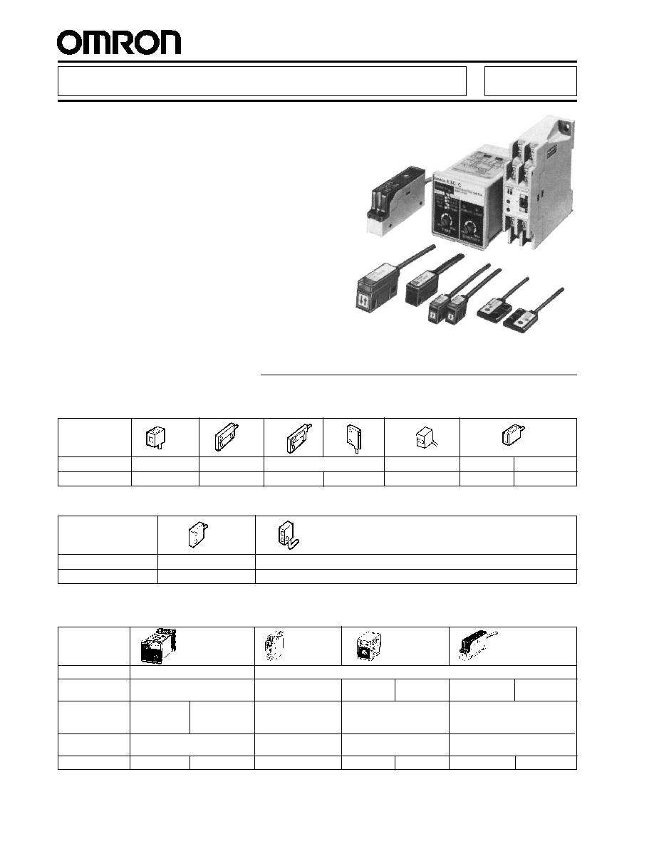
Shape
Fits 1/16 DIN
For S3D8
Miniature
Slim, prewired
panel cutout
controller
Supply voltage
100 to 240 VAC, 50/60 Hz
12 to 24 VDC
Output
Relay and NPN solid-state
NPN and PNP
NPN
PNP
NPN
PNP
solid-state
solid-state
solid-state
Timer functions
--
ON-delay
--
--
40 ms OFF-delay
OFF-delay
One-shot
Mounting style
Socket (included)
Track
Socket Track
(order separately)
Part number
E3C-A
E3C-C
E3C-WH4F
E3C-GE4
E3C-GF4
E3C-JC4P
E3C-JB4P
Special-Purpose Photoelectric Sensors E3C
Miniature Sensors with Separate
Amplifiers Fit Tight Spaces
s
Fast, 1 ms response time
s
Light incident indicator on sensor
s
Dust-resistant flat lens surface
s
New, thin side view model
s
Prewired sensors have 2 m (6.56 ft) cable
s
Amplifier with built-in ON-, OFF- and one-
shot delays available
s
New prewired DC amplifier designed for
track mounting has alarm output to signal
unstable sensing conditions
s
SENSORS
Ordering Information
Through-beam Type
Shape
Sensing distance 10 cm (3.94 in)
20 cm (7.87 in
30 cm (11.81 in)
50 cm (19.69 in)
1 m (3.28 ft)
2 m (6.56 ft)
Part number
E3C-S10
E3C-S20W
E3C-S30W
E3C-S30T
E3C-S50
E3C-1
E3C-2
Diffuse Reflective Type
Shape
Sensing distance
5 cm (1.97 in)
10 cm (3.94 in)
Part number
E3C-DS5W
E3C-DS10
s
AMPLIFIERS
E3C
E3C
3
s
ACCESSORIES
Description
Part number
Mounting brackets
U-shaped, for E3C-S10, with 10 mm (0.394 in) sensing distance gap
OAC-T1
U-shaped, for E3C-S10, with 20 mm (0.787 in) sensing distance gap
OAC-T2
U-shaped, for E3C-S10, with 30 mm (1.181 in) sensing distance gap
OAC-T3
L-shaped, for E3C-DS10
E39-L42
L-shaped, for E3C-S50
E39-L31
Sockets required for
Bottom surface mount socket
PYF08M
E3C-G
4 amplifier
Combination bottom surface and track-mount socket
PYF08A-E
Mounting track
DIN rail, 50 cm (1.64 ft) length
PFP-50N
DIN rail, 1 m (3.28 ft) length
PFP-100N
End plate
PFP-M
Spacer
PFP-S
s
REPLACEMENT PARTS
Description
Part number
Track-mount socket for E3C-A and E3C-C amplifiers
PF113A-E
Mounting bracket for E3C-1
E39-L41
Mounting bracket for E3C-2
E39-L42
Mounting bracket for E3C-J
4P
E39-L48
s
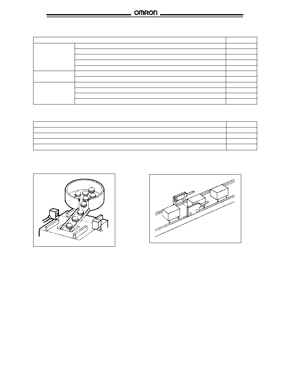
TYPICAL APPLICATIONS
E3C-S50
Detect parts coming from a bowl feeder
in a space-confined location
Space-saving flat sensors can detect small parts
in tight spaces
E3C-S20W
E3C
E3C
E3C
E3C
4
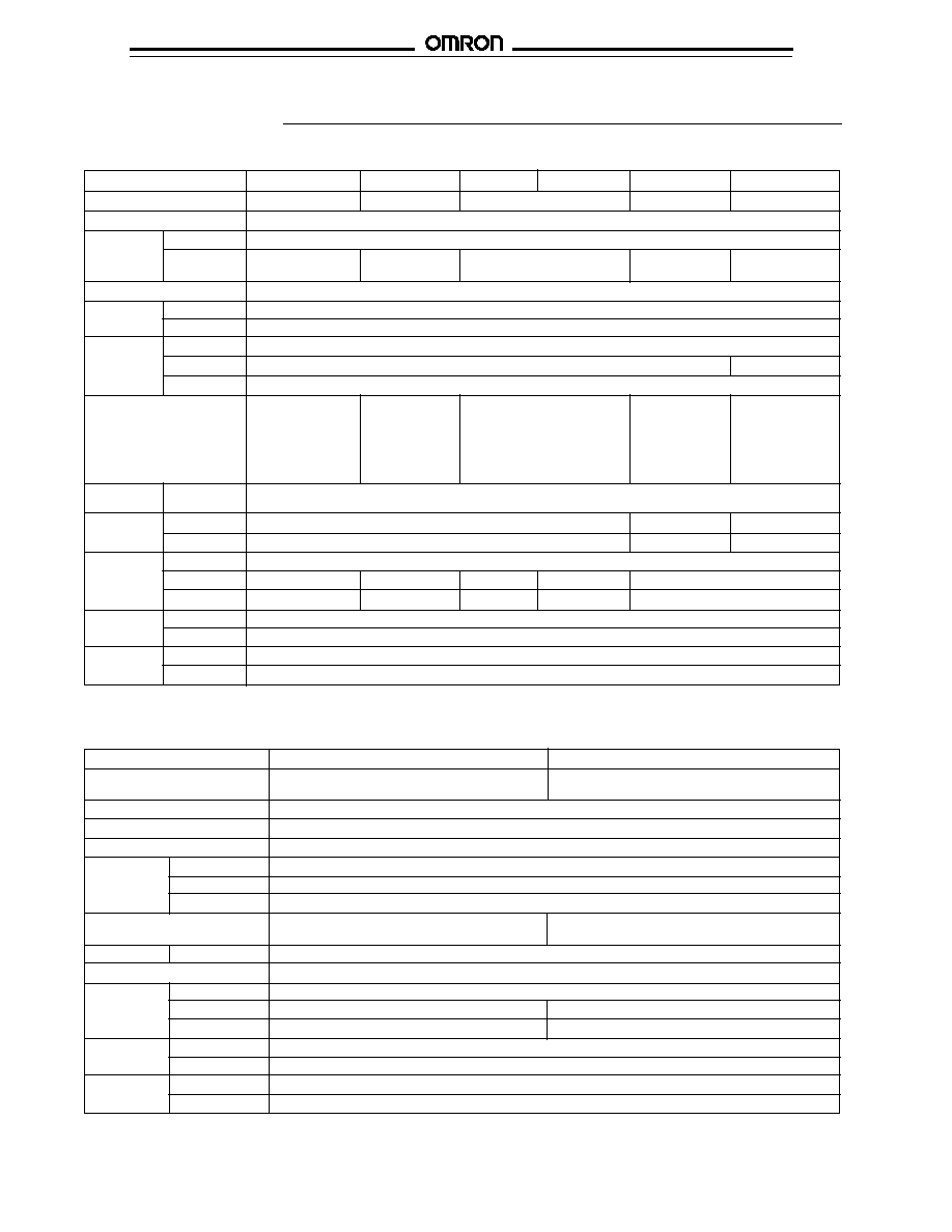
Specifications
Part number
E3C-S10
E3C-S20W
E3C-S30
E3C-S50
E3C-1
E3C-2
Sensing distance
10 cm (3.94 in)
20 cm (7.87 in)
50 cm (1.64 ft)
1 m (3.28 ft)
2 m (3.28 ft)
Light source
Pulse modulated infrared LED
Detectable
Type
Opaque materials
object
Size
2 mm (0.08 in)
2 mm (0.09 in)
3 mm (1.18 in)
4 mm (0.16 in)
8 mm (0.32 in)
min. dimension
min. dimension
min. dimension
min. dimension
min. dimension
Required amplifier
E3C-A, E3C-C, E3C-GE4, E3C-GF4, E3C-JC4P, E3C-JB4P, E3C-WH4F
Indicators
Emitter
Light Incident (red LED)
Receiver
None
Materials
Lens
Plastic, polycarbonate
Case
Plastic, polycarbonate
Zinc die-cast
Cable sheath Plastic, polyethylene
Mounting
Side surface
Side surface
Side surface with two
Side surface
Side surface
with two through
with two through through holes. Bracket
with two through with two through
holes. Brackets
holes.
E39-L31 optional, see
holes. Bracket
holes. Bracket
OAC-T1, OAC-T2,
Accessories
E39-L41 and
E39-L42 and
OAC-T3 optional,
hardware
hardware
see Accessories
included.
included.
Connections Prewired
Emitter: 2-conductor cable, 2 m (6.56 ft) length
Receiver: 2-conductor cable, 2 m (6.56 ft) length
Weight
Emitter
25 g (0.9 oz.)
30 g (1.1 oz.)
60 g (2.2 oz.)
Receiver
25 g (0.9 oz.)
30 g (1.1 oz.)
60 g (2.2 oz.)
Enclosure
UL
--
ratings
NEMA
1, 2, 12
1
1
1, 2, 12
1, 2, 4, 4X, 12
IEC 144
IP64
IP50
IP60
IP64
IP66
Approvals
UL
--
CSA
--
Ambient
Operating
-25
�
to 70
�
C (-13
�
to 158
�
F)
temperature
Storage
-25
�
to 70
�
C (-13
�
to 158
�
F)
Part number
E3C-DS5W
E3C-DS10
Sensing distance
5 cm (1.97 in) with 10 X 10 cm
10 cm (3.94 in) with 5 X 5 cm (1.97 in)
(3.94 in) 90% reflectance white mat paper
90% reflectance white mat paper
Detectable object type
Opaque and transparent materials
Required amplifier
E3C-A, E3C-C, E3C-GE4, E3C-GF4, E3C-JC4P, E3C-JB4P, E3C-WH4F
Indicators
Light Incident (red LED)
Materials
Lens
Plastic, polycarbonate
Case
Plastic, polycarbonate
Cable sheath
Plastic, polyethylene
Mounting
Side surface with two through holes.
Side surface with two through holes.
Bracket E39-L42 optional, see Accessories.
Connections
Prewired
4-conductor cable, 2 m (6.56 ft) length
Weight
50 g (1.8 oz.)
Enclosure
UL
--
ratings
NEMA
1
1, 2, 12
IEC 144
IP50
IP64
Approvals
UL
--
CSA
--
Ambient
Operating
-25
�
to 70
�
C (-13
�
to 158
�
F)
temperature
Storage
-25
�
to 70
�
C (-13
�
to 158
�
F)
s
THROUGH-BEAM TYPE
s
DIFFUSE REFLECTIVE TYPE
E3C
E3C
5
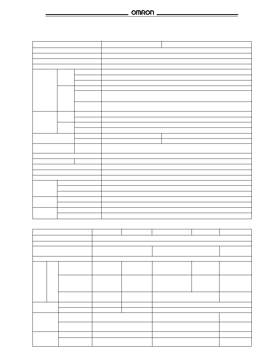
Part number
E3C-JB4P
E3C-JC4P
E3C-GE4
E3C-GF4
E3C-WH4F
Supply voltage
12 to 24 VDC
�
10%; 1 V max. permissible ripple peak-to-peak
Current consumption
50 mA
Operation mode
Light-ON/Dark-ON
Light-ON/Dark-ON,
Light-ON/Dark-ON,
switch selectable
jumper selectable
switch selectable
Sensitivity
Adjustable
Control DC
Type
PNP output
NPN output
NPN output
PNP output
NPN and PNP
output
solid-
with constant
open collector
state
current source
outputs
Max. load
100 mA max.
100 mA max.
Load (relay, sink)
100 mA max.
100 mA, 40 VDC
24 VDC
24 VDC
logic: 80 mA, 24 VDC
24 VDC
(each output)
Voltage logic (source):
1.5 to 4 mA
Max. on-state
0.7 VDC
0.7 VDC
1.2 VDC
0.7 VDC
voltage drop
Alarm
Type
PNP
NPN
--
output
Max. load
50 mA, 24 VDC 50 mA, 24 VDC
--
Response
ON
1 ms
1 ms or 2 ms max.,
1 ms or 2 ms max.,
time
selectable
switch selectable
OFF
1 ms or 40 ms, selectable
1 ms or 2 ms max.,
1 ms or 2 ms max.,
selectable
switch selectable
Circuit
Output short-circuit
Yes
Yes
Yes
protection
DC power supply
Yes
Yes
Yes
reverse polarity
s
AMPLIFIERS
AC Powered
Part number
E3C-A
E3C-C
Supply voltage
100 to 240 VAC, 50/60 Hz
Power consumption
3 VA max.
Operation mode
Light-ON/Dark-ON, switch selectable
Sensitivity
Adjustable
Control
Relay
Type
SPDT
output
Max. load
1 A, 240 VAC (p.f. = 1)
Min. load
1 mA, 5 VDC
DC
Type
NPN-SPST with constant current source
solid-
Max. load
Load (relay, sink) logic, 80 mA, 24 VDC
state
Voltage logic (source): 1.5 to 4 mA
Max. on-state
1.0 VDC
voltage drop
Response
ON
Solid-state
1 ms or 2 ms max., switch selectable
time
Contact
20 ms max.
OFF
Solid-state
1 ms or 2 ms max., switch selectable
Contact
20 ms max.
Timer functions
Type
--
ON-delay, OFF-delay, one-shot, switch selectable
Range
--
0.1 to 1 second or 1 to 10 seconds, switch selectable
Circuit
Output short-
Not available
protection
circuit
Indicators
Light Incident (red LED), Output Stability (green LED), Output Operation (red LED)
Materials
Case
Plastic
Mounting
Requires PF113A-E socket (included); socket mount to DIN rail track
Connections
Terminal screws on socket
Weight
220 g (7.8 oz.), including socket
Enclosure
UL
--
ratings
NEMA
1
IEC144
IP20
Approvals
UL
--
CSA
--
Ambient
Operating
-10
�
to 55
�
C (14
�
to 131
�
F)
temperature
Storage
-25
�
to 70
�
C (-13
�
to 158
�
F)
DC Powered
E3C
E3C
6
DC Amplifiers, continued
Part number
E3C-JB4P
E3C-JC4P
E3C-GE4
E3C-GF4
E3C-WH4F
Indicators
Light Incident (red LED), Output Stability (green LED)
Materials
Case
Plastic
Mounting
DIN rail track or mounting
Requires PYF08A-E
DIN rail track or
bracket E39-L48 (included)
or PYF08M
bottom surface with
or side surface with two
socket (not included).
two through holes.
through holes
Order separately
from Accessories.
Connections
Prewired with 5 conductor
Terminal screws
Terminal screws or
cable, 2 m (6.56 ft) length
on socket
direct connection to
S3D8 Sensor
Controller with
E99-C connector
(included).
Weight
80 g (2.8 oz.)
15 g (0.5 oz.)
100 g (3.5 oz.)
Enclosure
UL
--
--
NEMA
1, 2
1
IEC 144
IP50
IP20
Approvals
UL
--
CSA
--
Ambient
Operating
-10
�
to 55
�
C (14
�
to 131
�
F)
temperature
Storage
-25
�
to 70
�
C (-13
�
to 158
�
F)
s
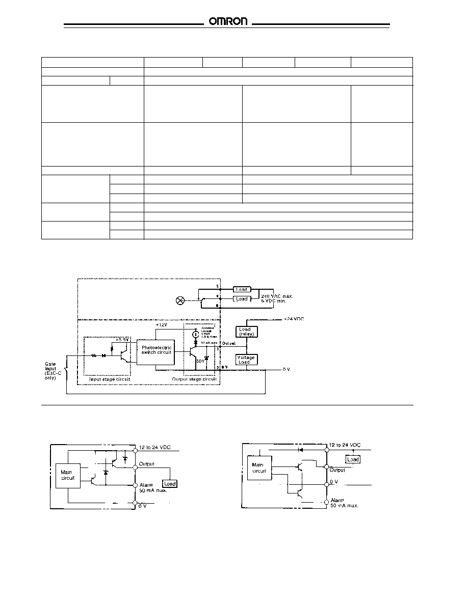
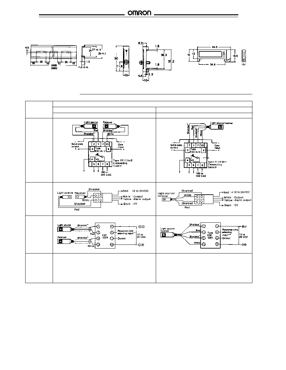
OUTPUT CIRCUIT DIAGRAMS
Amplifiers E3C-A, E3C-C
Amplifiers E3C-J
4P
NPN output type
E3C-JC4P
PNP output type
E3C-JB4P
E3C
E3C
7
50
10
1
0
20
40
60
80
100
Detecting distance (cm)
100
10
1
0 5 10 15 20 25 30 35 40 45 50
Detecting distance (cm)
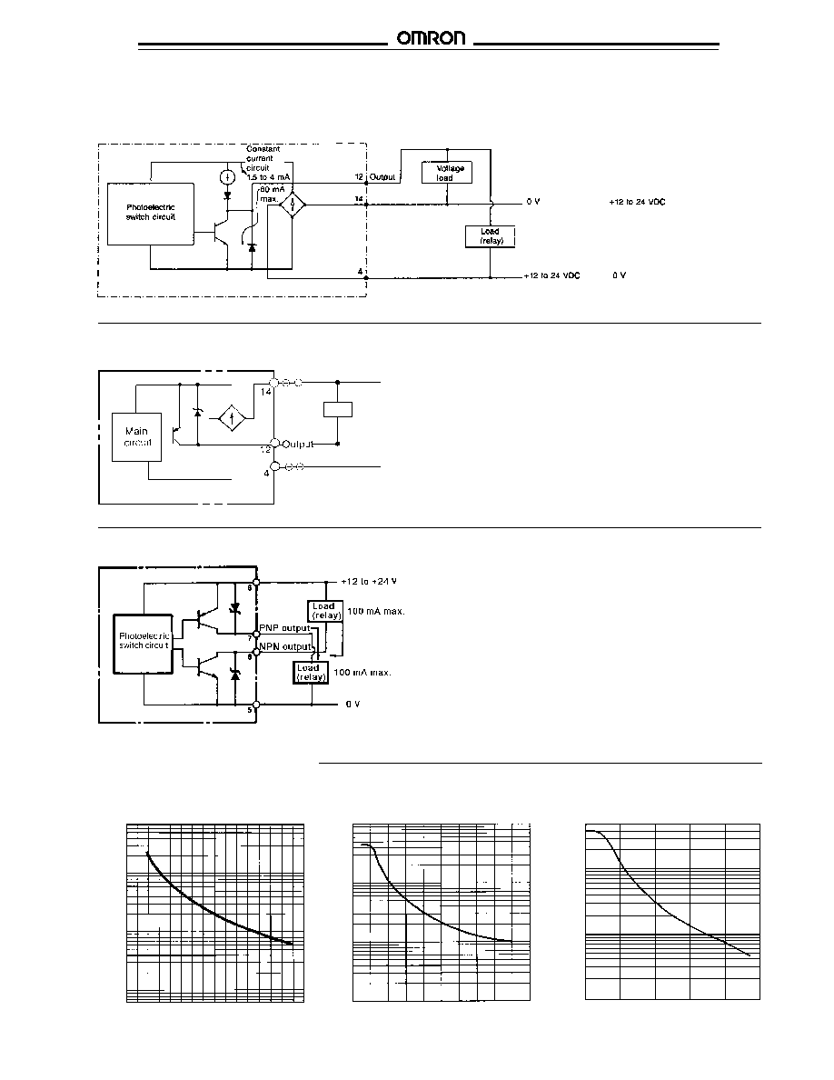
OUTPUT CIRCUIT DIAGRAMS, continued
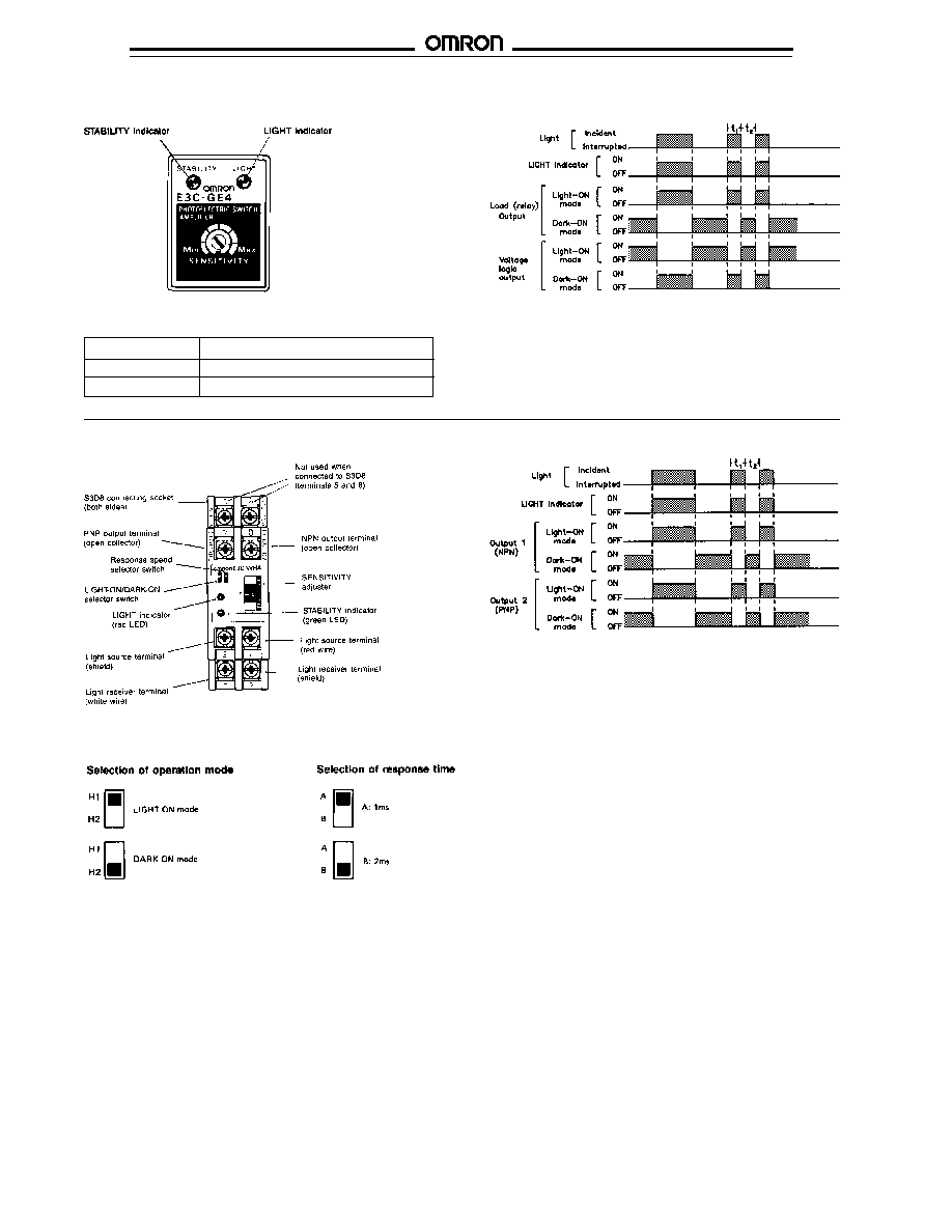
Amplifier E3C-GE4
Engineering Data
E3C-S20W
E3C-S10
s
EXCESS GAIN RATIO
0
5
10
15
Detecting distance (cm)
100
10
1
Amplifier E3C-WH4F
Excess gain ratio
Excess gain ratio
Light-ON
Dark-ON
PNP Output E3C-GF4
Excess gain ratio
E3C-S30T, E3C-S30W
Load
Light-ON
Dark-ON
0V
+12 to 24 VDC
+12 to 24 VDC
0V
E3C
E3C
8
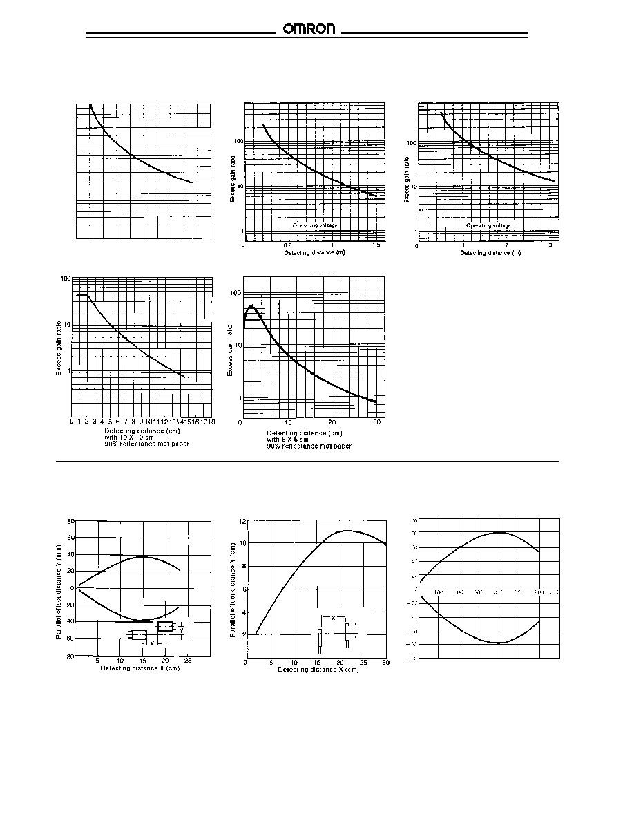
EXCESS GAIN RATIO, continued
E3C-DS5W
E3C-DS10
s
LIGHT SOURCE/RECEIVER SETTING RANGE
Separate type
E3C-S10
E3C-S20W
E3C-1
E3C-2
Excess gain ratio
E3C-S50
100
10
1
0 10 20 30 40 50 60 70 80 90 100
Detecting distance (cm)
Parallel offset distance Y (cm)
Detecting distance X (cm)
E3C-S30T, E3C-S30W
E3C
E3C
9
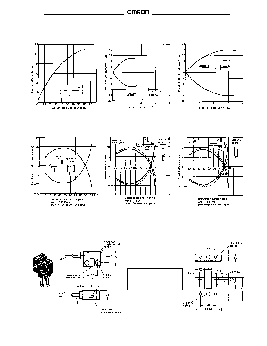
LIGHT SOURCE/RECEIVER SETTING RANGE, continued
Diffuse Reflective Type
E3C-DS5W
E3C-DS10 (Example 1)
E3C-DS10 (Example 2)
s
OPERATING RANGE
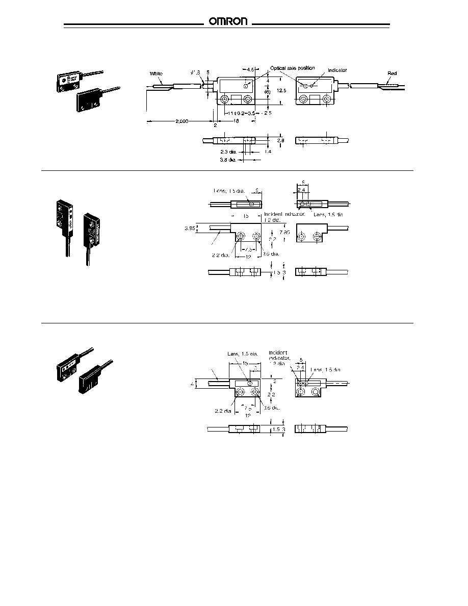
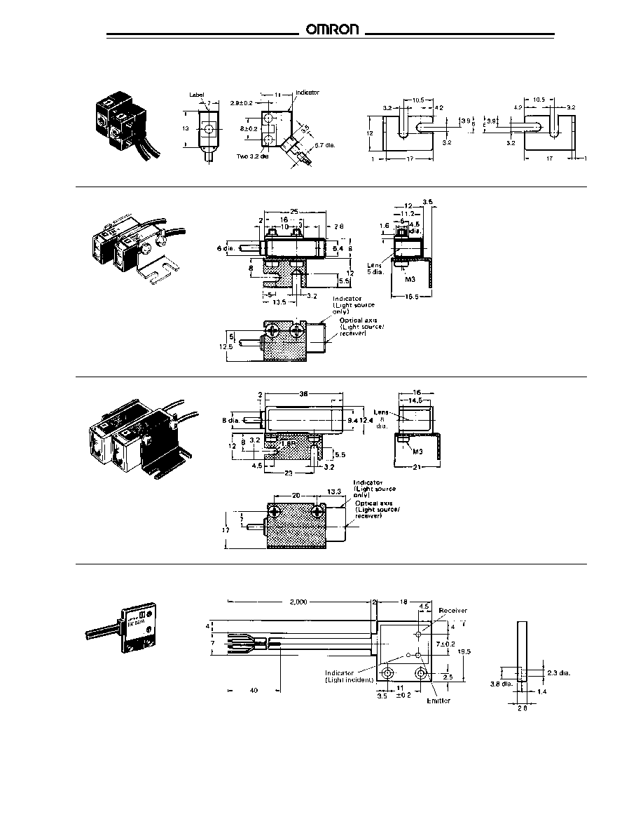
Dimensions
s
SENSORS
E3C-S10
Mount the emitter and receiver on
the legs of the U-shaped bracket so
they face each other. Dimension
"A" shows the fixed sensing
distance.
Part number
Dimension A
OAC-T1
10 mm (0.394 in)
OAC-T1
20 mm (0.787 in)
OAC-T3
30 mm (1.81 in)
Mounting Brackets for E3C-S10
Unit: mm
E3C-1
E3C-2
E3C-S50
E3C
E3C
10
E3C-S20W
Receiver
Light source
E3C-S30T
E3C-S30W
2 m (6,56 ft) cable, 1.8 mm OD
2 m (6,56 ft) cable, 1.8 mm OD
E3C
E3C
11
E3C-S50
E3C-1
E3C-2
NOTE:
E3C-1 is shown
mounted in E39-L41
bracket supplied with
each sensor.
NOTE:
E3C-2 is shown mounted
in E39-L42 bracket
supplied with each
sensor.
E39-L31 Optional Mounting Bracket
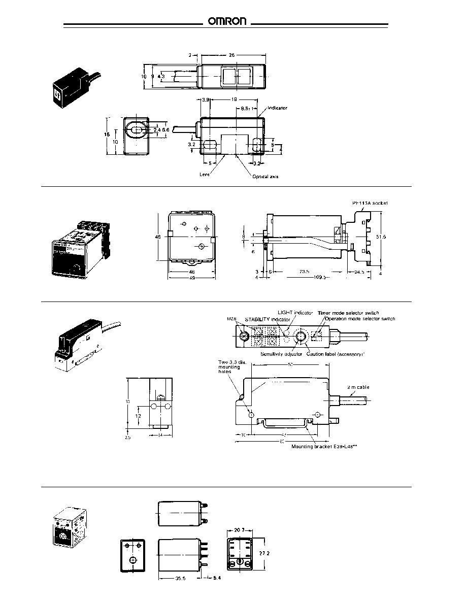
E3C-DS5W
E3C
E3C
12
NOTE:
Use mounting bracket
E39-L42, shown on
E3C-2; order separately
from Accessories.
s
AMPLIFIERS
E3C-A, E3C-C
E3C-JB4P, E3C-JC4P
NOTE: Socket PF113A-E and two hold-down clips are included with these amplifiers.
* Attach the caution label after adjusting the sensitivity adjuster.
** This is not necessary when mounting the amplifier
on DIN rail track.
E3C-DS10
E3C-GE4, E3C-GF4
NOTE:
Order required socket
PYF08A-E or PYF08M from
Accessories section.
E3C
E3C
13
Mounting holes
Socket PF113A-E and two hold-down
clips are supplied with E3C-A and E3C-C
amplifiers.
PF113A-E Track-Mount Socket
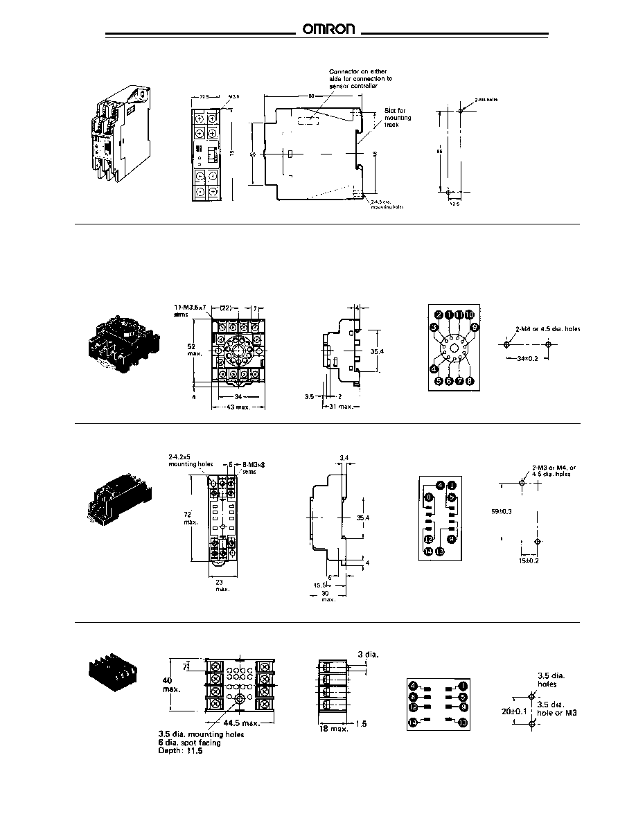
s
SOCKETS
Terminal
arrangement
(top view)
PYF08A-E Combination Track and Bottom Mount Socket for E3C-GE4, E3C-GF4
Terminal
arrangement
(top view)
Mounting holes
Mounting holes
E3C-WH4F
PYF08M Bottom Surface Mount Socket for E3C-GE4, E3C-GF4
Terminal arrangement
Mounting holes
(top view)
E3C
E3C
14
s
MOUNTING TRACK AND ACCESSORIES
PFP-100N/PFP-50N DIN Rail
PFP-M End Plate
PFP-S Spacer
Amplifier
Sensors
model
Through-beam type
Diffuse reflective type
E3C-S10, E3C-S20W, E3C-S30
s
, E3C-S50, E3C-1, E3C-2
E3C-DS5W, E3C-DS10
E3C-A,
E3C-C
E3C-JB4P
and
E3C-JC4P
E3C-GE4
Notes
*Shielded wires must not be peeled in excess of 2 cm
*Shielded wires must not be peeled in excess of 2 cm
(0.787 in) for receiver (white lead) and 5 cm (1.969 in) for
(0.787 in).
the light source (red lead).
**Response time is 1 ms when terminal 8 is left open and
**Response time is 1 ms when terminal 8 is left open and
2 ms when terminal 8 is short-circuited with the 0 V
2 ms when terminal 8 is short-circuited with the
terminal of the power supply (negative side).
0 V terminal of the power supply (negative side).
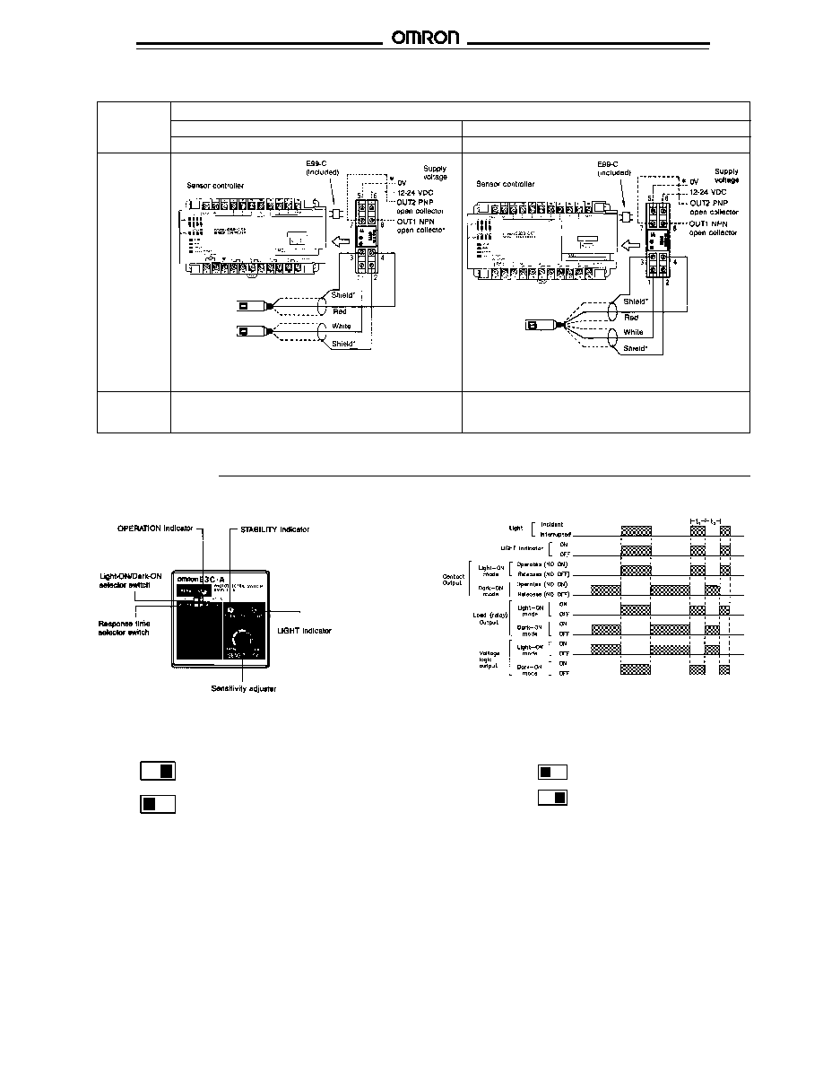
Connections
E3C
E3C
15
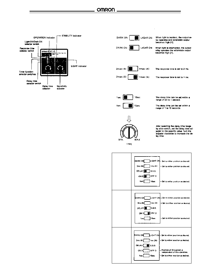
Selection of response time
2 msec (B)
1 msec (A)
The response time is set to 2 ms.
2 msec (B)
1 msec (A)
The response time is set to 1 ms.
Selection of operation mode
DARK ON
LIGHT ON
When light is incident, the output relay
operates and solid-state output becomes
high (H).
DARK ON
LIGHT ON
When light is interrupted, the output relay
operates and the solid-state output becomes
high (H).
NOTE: 1. Control output is produced only during the input time.
2. When t exceeds 1 ms or 2 ms, solid-state output is produced. To produce
relay contact output, t must be longer than 20 ms.
Amplifier
Sensors
model
Through-beam type
Diffuse reflective type
E3C-S10, E3C-S20W, E3C-S30
s
, E3C-S50, E3C-1, E3C-2
E3C-DS5W, E3C-DS10
E3C-WH4F
NOTE: Terminals 5, 6, 7, and 8 are not used when connected to S3D8
NOTE: Terminals 5, 6, 7, and 8 are not used when connected to S3D8
or S3D-F sensor controllers.
or S3D-F sensor controllers.
Notes
*Shielded wires must not be peeled in excess of
*Shielded wires must not be peeled in excess of
2 cm (0.787 in) for the receiver (white lead) and 5 cm
2 cm (0.787 in).
(1.969 in) for the light source (red lead).
Connections, continued
s
E3C-A Timing Chart
s
E3C-A Amplifier
Operation
E3C
E3C
16
s
E3C-C AMPLIFIER
Selecting timer function
ON D.
(ON-delay)
operation
OFF D.
(OFF-delay)
operation
O.S.D.
(One-shot
delay)
operation
Gate input operation
When the gate input terminal 9 is opened at HIGH level (6 to 30
VDC), the output relay performs the timer operation according
to the input signal (light incident or light interrupted).
When the gate input terminal 9 is short-circuited with the 0 V
terminal 2 at LOW level (0 to 2 VDC), the output relay releases
without regard to the input signal or output state. The terminal
generates an inhibit signal.
Selection of operation mode
Selection of response time
Setting the delay time
E3C
E3C
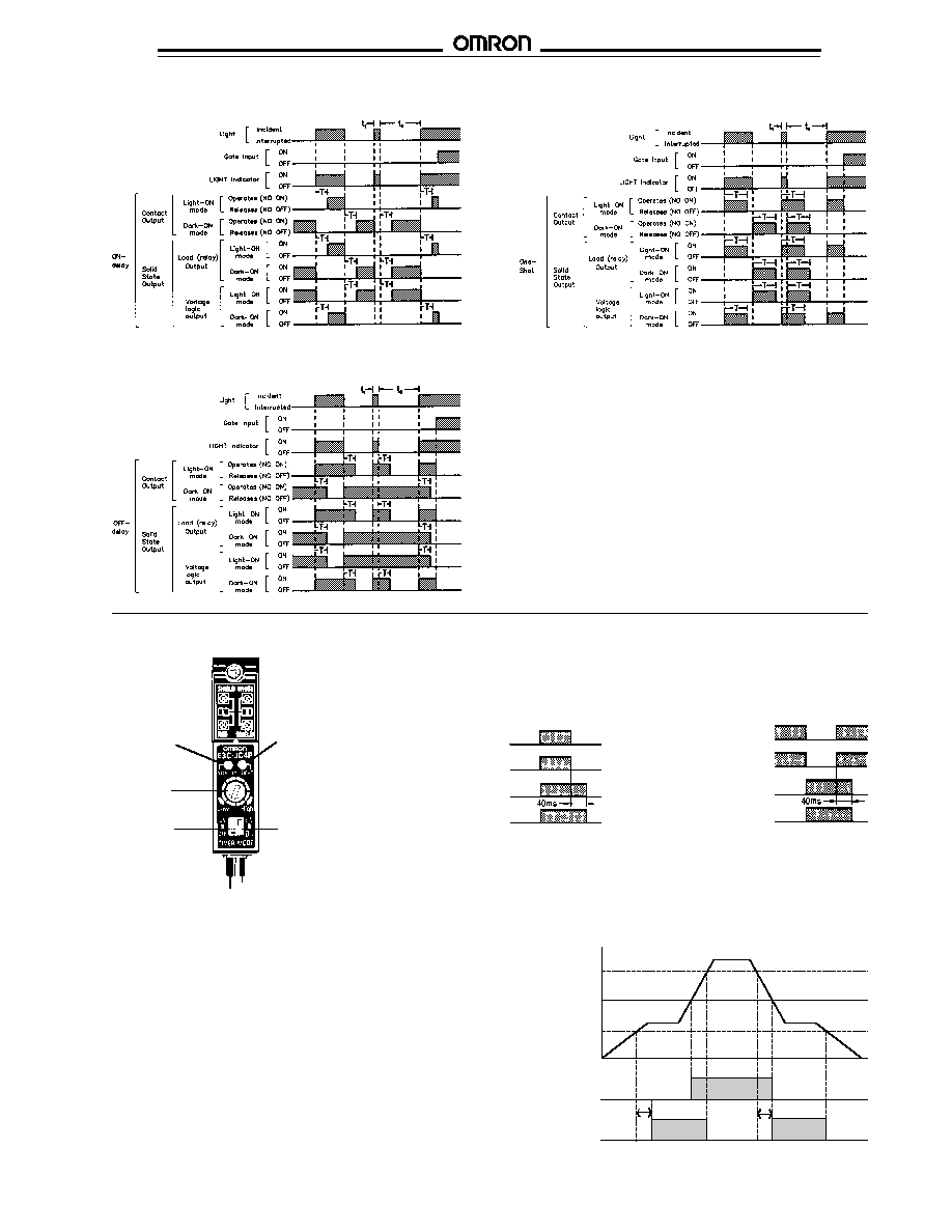
17
E3C-C ON-Delay Timing Chart
E3C-C One-Shot Timing Chart
E3C-C OFF-Delay Timing Chart
s
E3C-JB4P, E3C-JC4P AMPLIFIERS
Timing Charts
Light-ON
Light beam
Incident
Interrupted
LIGHT
ON
indicator
OFF
Transistor Output
ON
(1 ms)
OFF
Transistor Output
ON
(40 ms OFF-delay)
OFF
Dark-ON
Light beam
Incident
Interrupted
LIGHT
ON
indicator
OFF
Transistor Output
ON
(1 ms)
OFF
Transistor Output
ON
(40 ms OFF-delay)
OFF
Light-ON/
Dark-ON
operation
selector
switch
Sensitivity
adjuster
OFF-delay
selector
switch
Stability
indicator
(green LED)
Light
incident
(red LED)
The alarm output operates when the control output approaches
critical OFF or ON state for more than 300 ms. An unstable
state occurs when the amount of light incident upon the
receiving element is within 20% of the amount of light needed
to change the control output state.
The alarm output feature is designed to indicate gradual
changes in sensor/reflector position, atmosphere, temperature
or ambient light which result in an unstable control output. A
change occurring less than 300 ms will not cause the alarm
output to operate.
A 300 ms time delay is built into the alarm output circuit. This
prevents false triggering of the alarm output as the leading and
trailing edges of the object to be detected are sensed. The
time can be extended by using an ON-delay timer in the circuit.
Alarm Output Timing Chart
On
Off
On
Off
300 ms max.
300 ms max.
Operation level 120%
Operation level
Operation level 80%
Control output
(light on mode)
Self-diagnostic
output
Timing Charts
E3C
E3C
18
s
E3C-GE4 , E3C-GF4 AMPLIFIER
E3C-GF4 Timing Chart
NOTE: t
1
and t
2
must exceed selected response time (1 or 2 ms) before solid-state
output states will change.
Response
Wiring
1 ms
Terminal 8 open
2 ms
Terminal 8 shorted with terminal 4 (0 V)
s
E3C-WH4F AMPLIFIER
E3C-WH4F Timing Chart
NOTE: t
1
and t
2
must exceed selected response time (1 or 2 ms) before solid-state
output states will change.
Selection of response time

E3C
E3C
19
OMRON ELECTRONICS LLC
OMRON CANADA, INC.
One East Commerce Drive
885 Milner Avenue
Schaumburg, IL 60173
Scarborough, Ontario M1B 5V8
1-800-55-OMRON
416-286-6465
Cat. No. CEDSAX4
11/01
Specifications subject to change without notice.
Printed in the U.S.A.
OMRON ON-LINE
Global - http://www.omron.com
USA - http://www.omron.com/oei
Canada - http://www.omron.com/oci