 | –≠–ª–µ–∫—Ç—Ä–æ–Ω–Ω—ã–π –∫–æ–º–ø–æ–Ω–µ–Ω—Ç: E3C-L11M | –°–∫–∞—á–∞—Ç—å:  PDF PDF  ZIP ZIP |
Document Outline
- First Page
- Ordering Information
- Specifications
- Operation
- Engineering Data
- Dimensions
- Precautions
- Contacting Omron
R
2
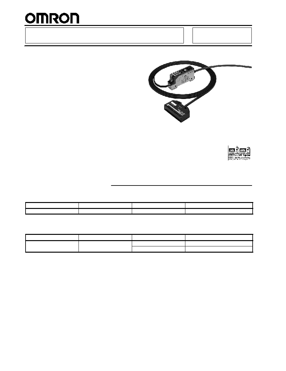
Glass Edge Detecting Sensor
E3C-L11M
Reliable detection of glass plates,
silicon wafers and plastic memory
media
H
Accurate detection even when objects
shift position to stair-step or fanned
arrangement
H
Detection not affected by rounded
edges or curling
H
Robotic cable for repeated flexing
H
Compact sensing head fits
space-confined installations
H
Remote amplifier for easy adjustments
H
Slim amplifier mounts on DIN rail track
Ordering Information
J
SENSING HEAD
Sensing method
Light source
Sensing distance
Part number
Diffuse
Infrared (860 nm)
20±10 mm
E3C-L11M
J
AMPLIFIER
Supply voltage
Timing function
Output configuration
Part number
12 to 24 VDC
40 ms OFF-delay or disabled
PNP open collector, 100 mA
E3C-JB4P
12 to 24 VDC
40 ms OFF delay or disabled
NPN open collector, 100 mA
E3C-JC4P
E3C-L11M
E3C-L11M
3
Specifications
J
RATINGS/CHARACTERISTICS
Sensing Head
Sensing distance
20±10 mm
Standard sensing object
Cut edge of transparent glass (t = 0.7 mm)
Differential travel (See Note 1.)
0.5 mm
Light source for emitter (with wavelength)
Infrared LED (860 nm)
Distance between sensing objects
10 mm (at 20-mm sensing distance)
Angle of sensing object (See Note 2.)
±10∞
Indicator
Light indicator (orange)
Ambient illumination
Incandescent lamp: 1,500 x
Ambient temperature
Operating
0∞C to 40∞C (32∞F to 104∞F) with no icing
Ambient temperature
Storage
--40∞C to 70∞C (--40∞F to 158∞F) with no icing
Relative humidity
Operating
35% to 85% with no condensation
Relative humidity
Storage
35% to 85%
Insulation resistance
20 M at 500 VDC
Dielectric strength
1,000 VAC, 50/60 Hz for 1 min
Vibration resistance
10 to 150 Hz, 0.75-mm double amplitude or 100 m/s
2
(10G) for 2 hrs each in X, Y,
and Z axes
Shock resistance
300 m/s
2
(30G) for 3 times each in X, Y, and Z axes
Enclosure rating
IEC IP50
Connection
2 m robotic cable
Weight
50 g
Material
Case
ABS
Material
Lens
PVC
Cable
2.4 x 4.3 robotic cable
1.7 dia. (30/0.08 dia.), 2 conductors
Accessories
Screws and instruction sheet
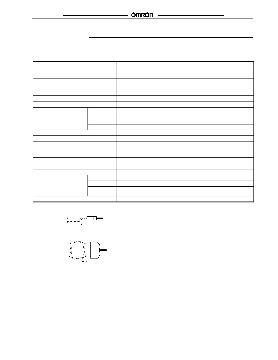
Note: 1. The differential travel is the hysteresis of the Sensor with the standard sensing object moving vertically.
Standard sensing object
Sensor
Vertical direction
Standard sensing object
Sensor
Rotation
2.
E3C-L11M
E3C-L11M
4
J
AMPLIFIER E3C-Jj
j
j
j
4P
Supply voltage
12 to 24 VDC ±10%, ripple (p-p): 1 V max.
Current consumption
50 mA max.
Control output
NPN open collector with 100-mA max. load current at 24 VDC (with 1-V residual voltage max.)
Indicators
Light indicator (red) and stability indicator (green)
Response time
1 ms ON, 1 ms OFF
Timer function
OFF-delay (0 or 40 ms selectable)
Sensitivity adjustment
4-turn adjuster
Connection
2 m cable
Operation
J
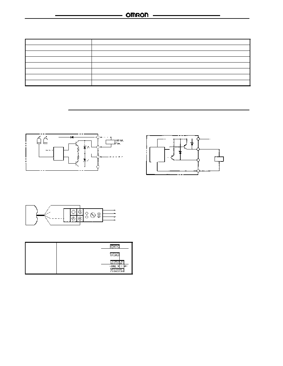
OUTPUT CIRCUIT
E3C-JC4P NPN Amplifier
E3C-JB4P PNP Amplifier
Load
Light
indicator
(red)
Stability
indicator
(green)
Photo-
electric
sensor
main cir-
cuit
Self-diagnostic
output (50 mA max.)
Brown
Black
Blue
Pink
12 to 24 VDC
Output
0 V
Output
12 to 24 VDC
0 V
Main
circuit
Load
Alarm
50 mA max.
J
CONNECTION
Brown
Black
Blue
Pink
12 to 24 VDC
E3C-L11M Sensor Unit
White
Shield
Shield
Red
E3C-Jj4P Amplifier Unit
Control output
0 V
Self-diagnostic output
J
E3C-L11M AND E3C-Jj4P
Timing chart
Light received
Light not received
Light indicator
(orange)
ON
OFF
Output transistor
Load (relay)
ON
OFF
ON
OFF

E3C-L11M
E3C-L11M
5
Engineering Data
J
OPERATING RANGE
J
SENSING ANGLE
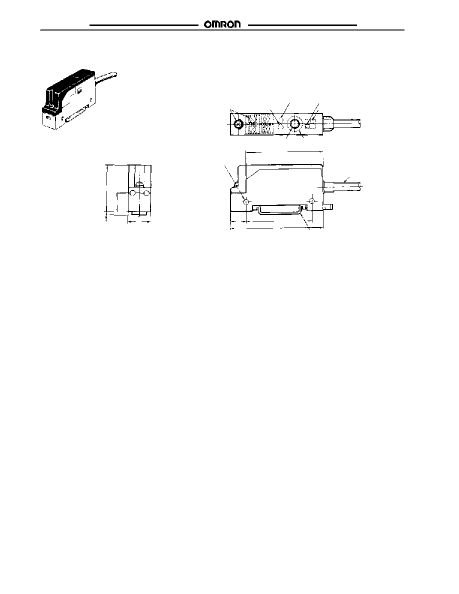
Dimensions
Unit: mm (inch)
J
E3C-L11M
Optical axis
Lens
Two, mounting holes
Two, 4.3 dia.
Light indicator (orange)
Mounting Dimensions
Two, M-4
2-m-long, 2.4 x 4.3 robot code
(1.7 dia. (30/0.08 dia.) two conductors)
30 (1.18)
50
(1.97)
20
12
(0.47)
5
16 (0.63)
(0.79)
20
0.2
24.5 (0.96)
E3C-L11M
E3C-L11M
6
J
E3C-JB4P, E3C-JC4P
30
12
14
2.5
M2.6
STABILITY indicator
LIGHT indicator
Timer mode selector switch
Operation mode selector switch
Sensitivity adjuster
Caution label (accessory)*
Two 3.3 dia.
mounting
holes
50
10
43
60
2 m cable
Mounting bracket E39-L48**
* Attach the caution label after adjusting the sensitivity adjuster.
** This is not necessary when mounting the amplifier on DIN rail track.

E3C-L11M
E3C-L11M
Precautions
J
ENVIRONMENT
Do not use the E3C-L11M in the following places:
∑
Places exposed to direct sunlight.
∑
Places with high humidity that may cause condensation.
∑
Places with corrosive gas.
∑
Places with vibration or shock directly affecting the Sensor.
Do not use the E3C-L11M at a voltage that exceeds the rated
voltage range, or the E3C-L11M may be damaged.
Do not make mistakes in wiring, such as mistakes in polarity, or
the E3C-L11M may be damaged.
Do not short-circuit the load, or the E3C-L11M may be damaged.
Do not connect AC to the E3C-L11M, or the E3C-L11M may be
damaged.
J
CONNECTION AND MOUNTING
∑
A maximum of 24 VDC±10% can be imposed on the
E3C-L11M. Check that the voltage of the power supply is
within the permissible range before turning on the E3C-L11M.
The power supply must be constructed so that the secondary
circuit is insulated with an isolating transformer.
∑
Do not wire power lines or high-tension lines alongside the
lines of the E3C-L11M in the same conduit, otherwise the
E3C-L11M may be damaged or malfunction due to induction.
Be sure to wire the lines of the E3C-L11M separated from
power lines or high-tension lines or laid in an separate,
shielded conduit.
∑
Do not strike the E3C-L11M with a hammer when mounting
the E3C-L11M, or the water-resistant properties of the
E3C-L11M will be lost.
J
CLEANING
Do not attempt to clean the E3C-L11M using paint thinner, or the
surface of the E3C-L11M will be damaged.
J
MOUNTING
The torque required to tighten each screw must be 7 kgf S cm
(0.71 N S m) maximum. Excessive tightening torque may damage
the Sensor Unit and Amplifier Unit.
J
POWER SUPPLY
If a standard switching power supply is connected to the
E3C-L11M, be sure to ground the FG (frame ground) and G
(ground) terminals of the switching power supply. The E3C-L11M
may malfunction due to switching noise that will be generated
from the switching power supply if these terminals are not
grounded.
Cat. No.
CEDSAX4
11/01
Specifications subject to change without notice. Printed in U.S.A.
OMRON ELECTRONICS LLC
One East Commerce Drive
Schaumburg, IL 60173
NOTE: DIMENSIONS SHOWN ARE IN MILLIMETERS. To convert millimeters to inches divide by 25.4.
1-800-55-OMRON
OMRON CANADA, INC.
885 Milner Avenue
Scarborough, Ontario M1B 5V8
416-286-6465
R
OMRON ON--LINE
Global -- http://www.omron.com
USA -- http://www.omron.com/oei
Canada -- http://www.omron.com/oci