2
Special-Purpose Photoelectric Sensor
E3C-L
Miniature Convergent Beam Sensor
With Separate Amplifier
H
Ignores background objects to prevent false
signaling in inspection and mark detection
applications
H
Fast, 1 ms response time
H
Prewired with 2 m (6.56 ft) cable
H
Choose AC or DC amplifiers
H
Amplifier with built-in ON-, OFF- and
one-shot timer functions available
H
Prewired DC amplifiers offer fine sensitivity
adjustment and diagnostic alarm output
Ordering Information
J
SENSORS
Part number
E
3C-LS3R
Method of detection
Convergent beam diffuse reflective
Application
Mark detection and parts inspection
Sensing distance
3�0.3 cm (1.18�0.118 in)
Light source
Red LED (680 nm)
J
AMPLIFIERS
Part number
E
3C-A
E
3C-C
E
3C-WH4F
E
3C-GE4
E
3C-GF4
E
3C-JC4P
E
3C-JB4P
Description
Fits 1/16 DIN
panel cutout
For S3D8
Controller
Miniature
Slim, prewired
Supply voltage
100 to 240 VAC, 50/60 Hz
12 to 24 VDC
Output
Relay and NPN solid-state NPN and PNP
solid-state
NPN
solid-state
PNP
solid-state
NPN
PNP
Timer functions
--
ON-delay
OFF-delay
One-shot
--
--
40 ms OFF-delay
Mounting style
Socket (included)
Track
Socket Track
(order separately)
E3C-L
E3C-L
3
J
ACCESSORIES
Description
Part number
Mounting bracket for sensor
E
39-L41
Sockets required for E
3C-GE4 amplifier
Bottom surface mount socket
PYF
08M
q
p
Combination bottom surface and track-mount
socket
PYF
08A-E
Mounting track
DIN rail, 50 cm (1.64 ft) length
PFP-
50N
g
DIN rail, 1 m (3.28 ft) length
PFP-
100N
End plate
PFP-M
Spacer
PFP-S
J
REPLACEMENT PARTS
Description
Part number
Track-mount socket for E
3C-A and E3C-C amplifiers
PF
113A-E
Specifications
Part number
E
3C-LS3R
Method of detection
Convergent beam diffuse reflective
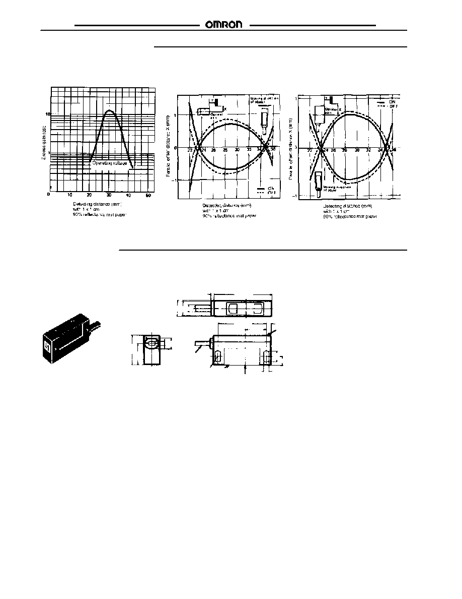
Sensing distance
3 �0.3 cm (1.18 �0.118 in)
with 1 x 1 cm (0.39 x 0.39 in)
90% reflectance mat paper
Light source
Pluse modulated red LED (680 nm)
Detectable object type
Opaque objects
Required amplifier
E
3C-A, E3C-C, E3C-GE4, E3C-GF4, E3C-JC4P, E3C-JB4P, E3C-WH4F
Mutual interference protection
Provided
Indicators
Light incident (red LED)
Materials
Lens
Plastic
Materials
Case
Plastic
Cable sheath
Plastic, polyethylene
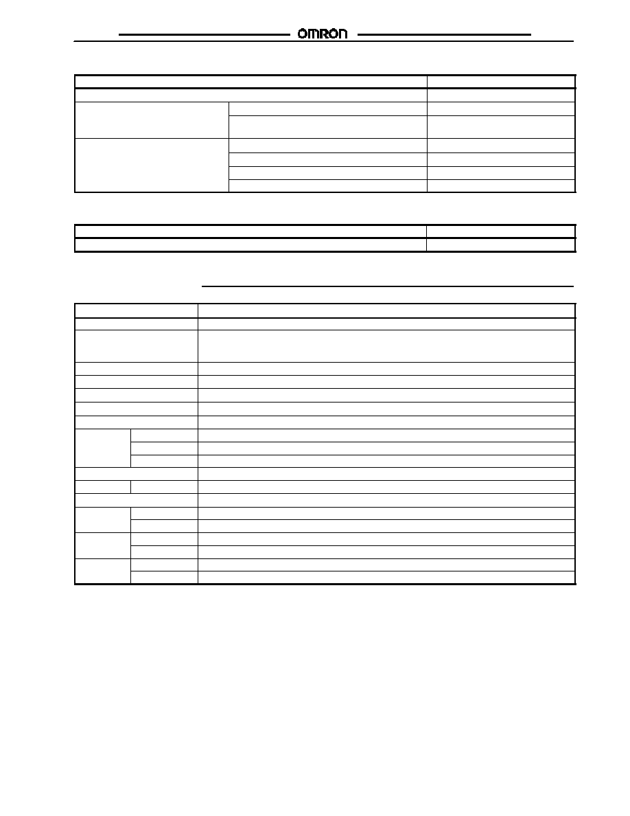
Mounting
Side surface with two through holes; Bracket E39-L41 optional. See Accessories
Connections
Prewired
4-conductor cable, 2 m (6.56 ft) length
Weight
55 g (1.9 oz.)
Enclosure
NEMA
1, 2, 12
Enclosure
ratings
IEC 144
IP64
Approvals
UL
Recognized
Approvals
CSA
--
Ambient
Operating
-25_ to 70_C (-13_ to 158_F)
Ambient
temperature
Storage
-25_ to 70_C (-13_ to 158_F)
J
AMPLIFIERS
Refer to the E
3C data sheet for details about output circuit diagrams, amplifier connections and operation.
E3C-L
E3C-L
Operation
J
SENSITIVITY ADJUSTMENT
Select the proper sensitivity adjustment
method based on the conditions listed in
the table. Both methods assume the
amplifier is set to DARK-ON operation
mode.
Conditions
Adjustment method
The reflection factor of the
object to be detected is equal
to, or higher than, that of the
background object.
The reflection factor of the
objected to be detected is
lower than that of the
background object.
Use Method 1.
Use Method 2.
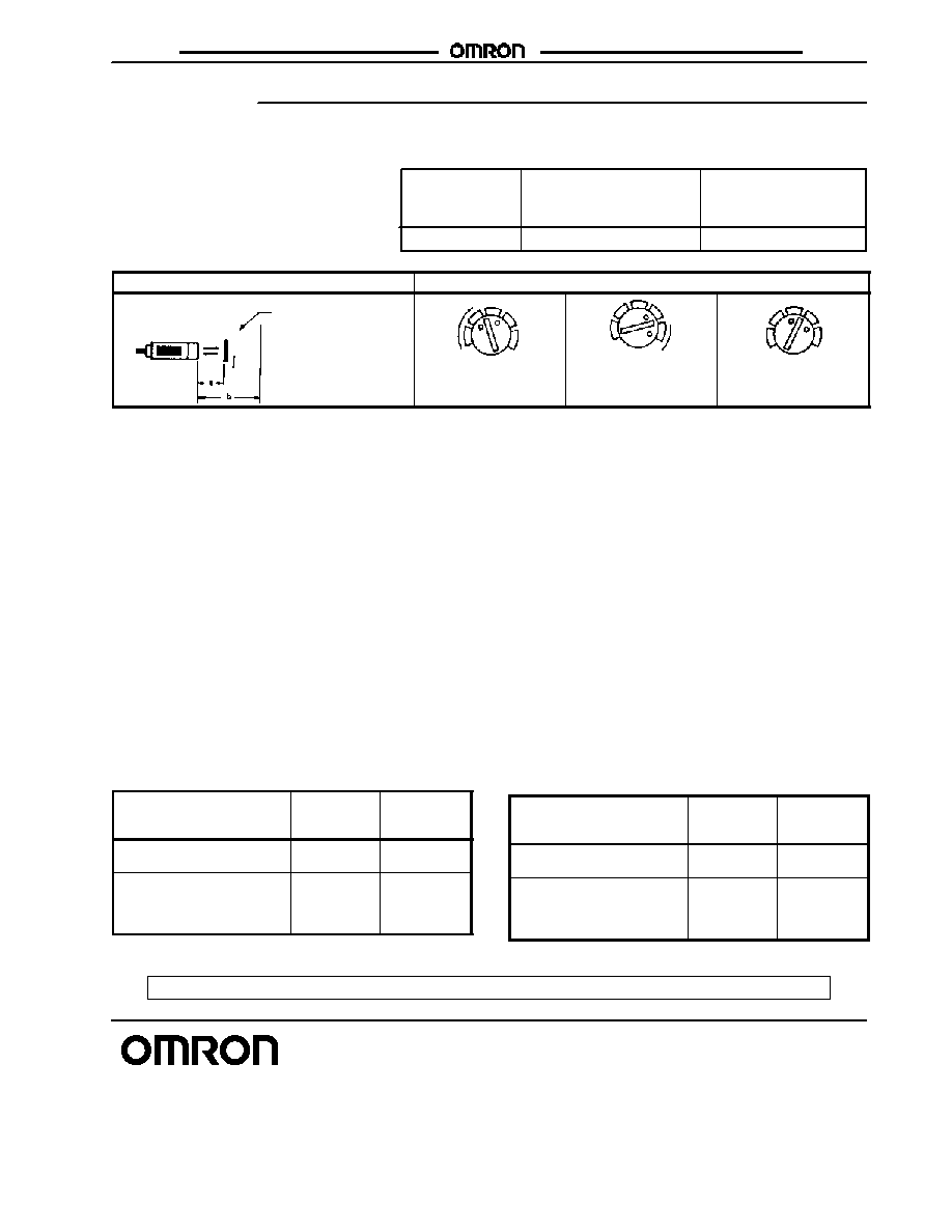
Distance between sensor and object
Sensitivity adjuster positions
Photoelectric
Sensor
Object to be
detected
Background
A
Reference
point A
Reference
point B
B
Optimum setting
between A and B
A
B
Adjustment Method 1
1. Set distance "A" between the sensor and the object to be
detected to 30 mm (1.18 in)
2. Set the sensitivity adjuster to the MAXIMUM position (fully
clockwise) and check that both the STABILITY and LIGHT
indicators of the amplifier unit light. If both indicators do not
light, move the sensor back and forth within the range of 2 to
3 mm (0.079 to 0.118 in) until the indicators light.
3. Remove the object to be detected and gradually turn the
sensitivity adjuster counterclockwise toward MINIMUM posi-
tion to find the point where the LIGHT and STABILITY indica-
tors change from lit to dark. Assume this is reference point
"B" on the sensitivity adjuster.
4. Place the object to be detected in position.
5. Gradually turn the sensitivity adjuster further counterclock-
wise toward MINIMUM position to find a point where the
LIGHT and STABILITY indicators change from lit to dark.
Assume this is reference point "A" on the sensitivity adjuster.
6. Set the sensitivity adjuster between reference points "A" and
"B" for the optimum sensitivity adjustment. Finally, confirm
that the LIGHT and STABILITY indicators operate as shown
in the table at the right.
Sensing condition
LIGHT
indicator on
amplifier
STABILITY
indicator on
amplifier
When the object to be
detected is present
ON
ON
When only the background
object is present, and the
object to be detected is not
present.
OFF
ON
Adjustment Method 2
1. Set distance "B" between the sensor and the background
object to 30 mm (1.18 in).
2. Remove the object to be detected.
3. Set the sensitivity adjuster to the MAXIMUM position (fully
clockwise) and check that both the STABILITY and LIGHT
indicators of the amplifier unit light. Gradually turn the sensi-
tivity adjuster counterclockwise toward MINIMUM position to
find the point where the LIGHT and STABILITY indicators
change from lit to dark. ASSUME this is reference point "B"
on the sensitivity adjuster.
4. Place the object to be detected in position.
5. Gradually turn the sensitivity adjuster further clockwise to-
ward MINIMUM position to find a point where the LIGHT
indicator changes from dark to lit, and the STABILITY indica-
tor from lit to dark. Assume this is reference point "A" on the
sensitivity adjuster.
6. Set the sensitivity adjuster between reference points "A" and
"B" for the optimum sensitivity adjustment. Finally, confirm
that the LIGHT and STABILITY indicators operate as shown
in the table at the right.
Sensing condition
LIGHT
indicator on
amplifier
STABILITY
indicator on
amplifier
When the object to be
detected is present
OFF
ON
When only the background
object is present, and the
object to be detected is not
present.
ON
ON
Cat. No. CEDSAX4 11/01 Specifications subject to change without notice. Printed in U.S.A.
OMRON ELECTRONICS LLC
One East Commerce Drive
Schaumburg, IL 60173
NOTE: DIMENSIONS SHOWN ARE IN MILLIMETERS. To convert millimeters to inches divide by 25.4.
1-800-55-OMRON
OMRON CANADA, INC.
885 Milner Avenue
Scarborough, Ontario M1B 5V8
416-286-6465
R
OMRON ON--LINE
Global -- http://www.omron.com
USA -- http://www.omron.com/oei
Canada -- http://www.omron.com/oci