Document Outline
- Front Page
- Ordering Information
- Specifications
- Operation
- Engineering Data
- Dimensions
- Installation
- Precautions
R
2
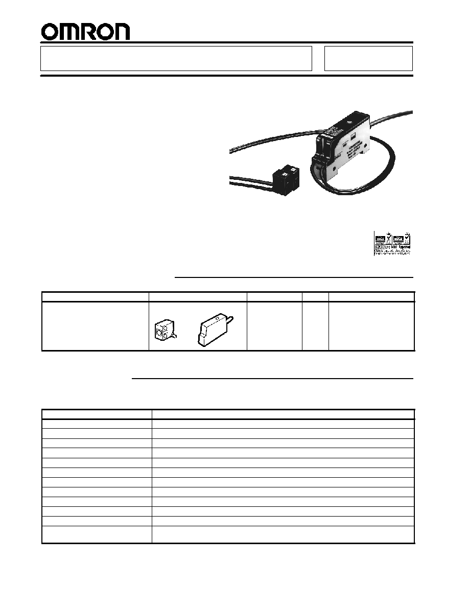
Single-Point Optical Through--Beam Sensor
E3C-T1
Compact, Narrow-View Sensor Is
Ideal for Sensing Wafers -- Using
OMRON's Unique "Pin-point" LED
H
0.1-ms ultra-high-speed response
H
Safer and more cost-effective than
comparable laser products
H
Use the E3C-T1 amplifier's turbo feature
combined with the sensor's "pin-point" red
LED, to achieve a visible 1.2-mm-diameter
spot at a sensing distance of 12 cm
H
The flexible robotics cable makes E3C-T1
ideal for applications requiring remote
sensor placement on moving parts
Ordering Information
Description
Appearance
Sensing distance
Output
Part number
Through-beam sensor and amplifier
Sensing head
Amplifier
50 cm
NPN
E3C-T1
(Sensor and Amplifier)
Specifications
H
RATINGS/CHARACTERISTICS
Part number
E3C-T1
Method of detection
Through-beam
Light source for emitter
Red LED (670 nm)
Sensing distance
50 cm (1.64 ft)
Direction angle
1� max.
Minimum sensing object
0.5-mm dia. (opaque object)
Power supply voltage
12 to 24 VDC �10%, ripple (p-p): 1 V max.
Current consumption
50 mA max. (70 mA max. with turbo switch turned ON)
Response time
0.1 ms max. for both operating and release
Indicators
Light incident (red LED), stability (green LED)
Control output
Load current: 100 mA max., NPN open collector with a maximum residual voltage of 1 V
Operation mode
Light-ON and Dark-ON switch selectable
Connection method
Sensor: Preleaded (standard cable length: 1 m)
Amplifier: Terminal block, preleaded (standard cable length: 2 m)
(This table continues on the next page.)
E3C-T1
E3C-T1
3
Specifications Table
-- continued from previous page
Part number
E3C-T1
Ambient illumination
Incandescent lamp: 3,000 x max.
Sunlight: 10,000 x max.
Ambient
temperature
Operating
--10�C to 40�C (14�F to 104�F) with no icing or condensation
Relative humidity
35% to 85%
Vibration resistance
10 to 55 Hz, 1.5-mm double amplitude for 2 hrs each in X, Y, and Z axes
Shock resistance
500 m/s
2
(approx. 50G) for Sensing head: and 300 m/s
2
(approx. 30G) for Amplifier for 3 times
each in X, Y, and Z axes
Enclosure ratings
IEC IP64 for Sensing head: and IP20 for Amplifier
Material
Case
ABS
Material
Cover
Polycarbonate
Lens
Acrylic
Weight
Sensing head: Approx. 50 g with 1-m cable
Amplifier: Approx. 80 g with 2-m cable
Operation
H
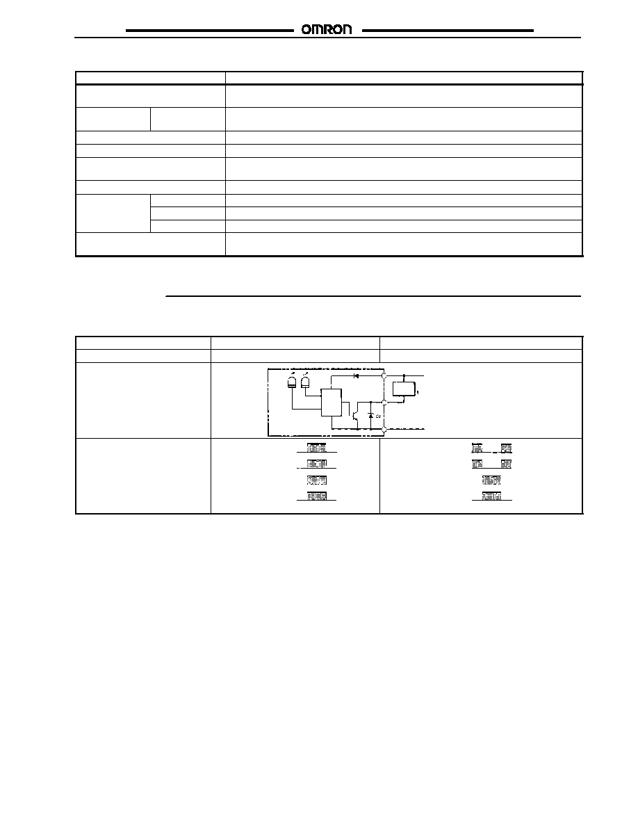
OUTPUT CIRCUIT
Operation mode selector
LIGHT ON
DARK ON
Output transistor
ON when light is received
ON when light is interrupted
Output circuit
Light
indicator
(red)
Stability
indicator
(green)
Photo-
electric
sensor
main
circuit
Brown
12 to 24 VDC
Load
(relay) Load current
Control output
Black
Blue
0 VDC
Timing chart
Light indicator
(red)
Output
transistor
Load (relay)
ON
OFF
ON
OFF
Operate
Release
Light received
Light not received
(Between brown and black)
Light indicator
(red)
Output
transistor
Load (relay)
ON
OFF
ON
OFF
Operate
Release
Light received
Light not received
(Between brown and black)
E3C-T1
E3C-T1
4
Engineering Data
H
PARALLEL OPERATING RANGE
(TYPICAL)
H
EXCESS GAIN RATIO
(TYPICAL)
P
a
r
a
llel
oper
at
ing
r
ange
Y
(mm)
Set distance X (cm)
Exce
ss
g
a
i
n
r
a
t
i
o
Sensing distance (cm)
Sensing distance
Dimensions
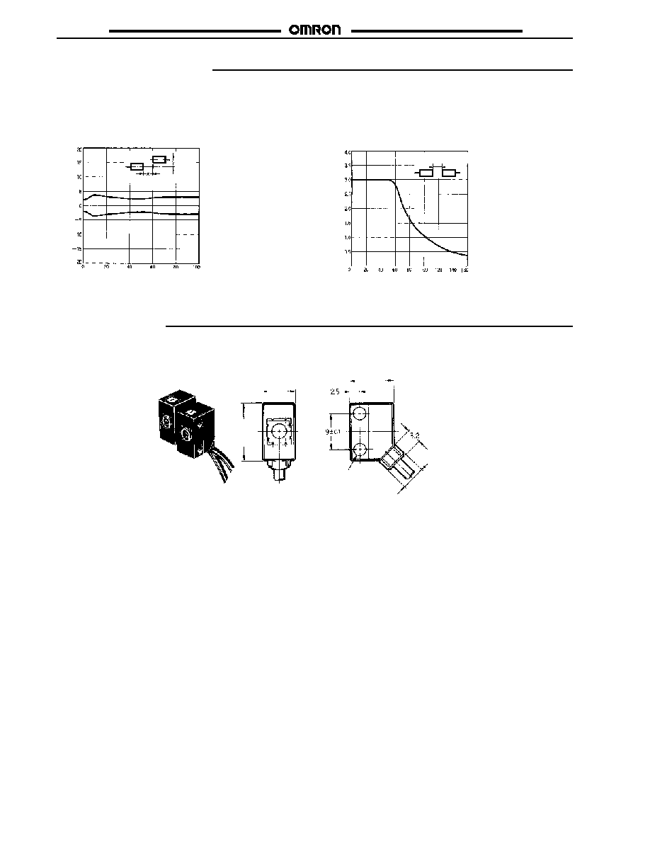
H
SENSING HEAD
E3C-T1L (Emitter)
E3C-T1D (Receiver)
Cable:
Robotics cable
2.4-mm dia. (60/0.08 dia.)
Standard length: 1 m
Weight:
Approx. 50 g
Two, 3.2 dia.
5.7 dia.
14
(0.55)
11
(0.43)
8
(0.31)
Unit: mm (inch)
E3C-T1
E3C-T1
5
H
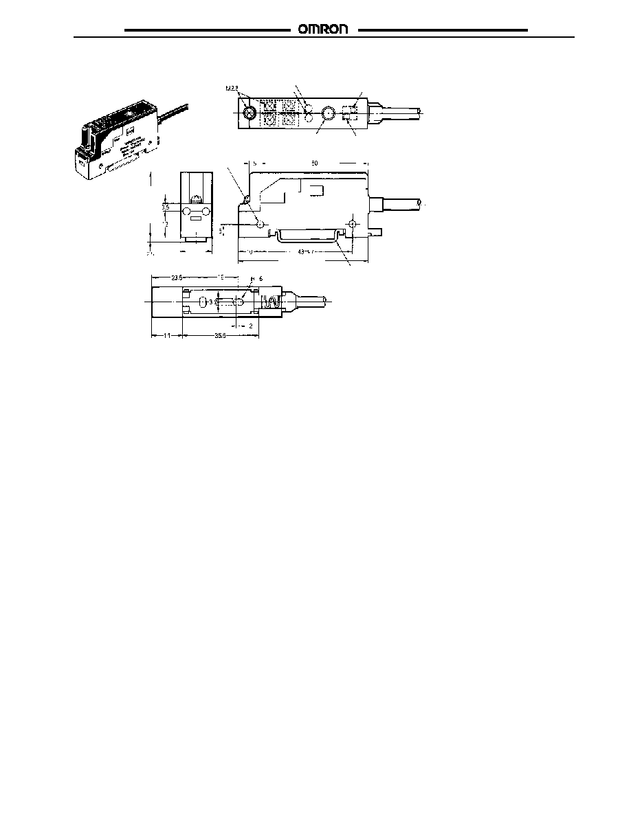
AMPLIFIER
E3C-T1A
Cable:
Polyvinyl chloride-covered cable
4-mm dia. (18/0.12 dia.), 3 cores
Standard length: 2 m
Weight:
Approx. 80 g
Note:
Themountingbracketisnot requiredfor
DIN-rail mounting.
Light
indicator
Stability
indicator
Operating
mode selector
Sensitivity
adjustment
volume
Turbo switch
Two, 3.3 dia.
Mounting bracket
(Accessory for
Amplifier) See note.
30
(1.18)
60
(2.36)
14
(0.55)
E3C-T1
E3C-T1
6
Installation
H
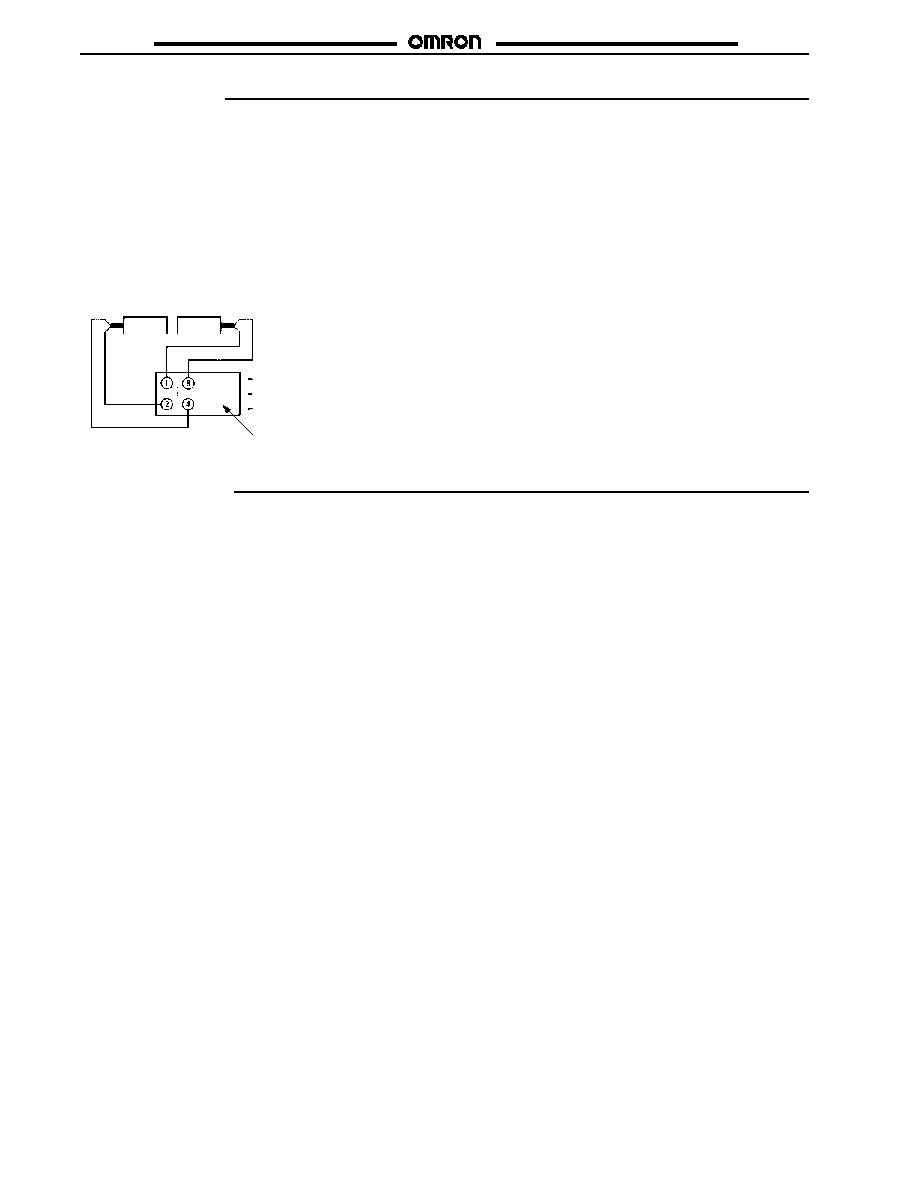
SENSOR AND AMPLIFIER CONNECTIONS
�
Be sure to connect the sensing heads to the dedicated
E3C-T1A Amplifier.
�
To avoid damage to the Sensor, DO NOT connect the
E3C-T1L Emitter or E3C-T1D Receiver to the E3C-JC4,
E3C-JC4P, or the E3C-JB4P.
�
Be sure that the length of the bare core of each cable is 2 cm
maximum.
�
Securely tighten all terminal screws after wiring.
Emitter
Receiver
White
Shield
Brown (12 to 24 VDC)
Black (Output)
Blue (0 VDC)
Red
Shield
E3C-T1A Amplifier
H
OPTICAL AXIS ADJUSTMENT
The E3C-T1 is used for the detection of minute objects. Because
the beam spot is very small, it may take some time to adjust the
optical axis.
For mounting, move the emitter and receiver up, down, left, and
right to position them in the center of the area that will turn the
light indicator on. Then, mount the emitter and receiver securely.
Precautions
H
ENVIRONMENT
To avoid damage to the E3C-T1:
�
Do not use the E3C-T1 in places with explosive or flammable
gas.
�
Do not impose any voltage exceeding the rated voltage on the
E3C-T1.
�
Do not short-circuit the load connected to the E3C-T1.
�
DO NOT connect the E3C-T1L Emitter or E3C-T1D Receiver to
the E3C-JC4, E3C-JC4P, or the E3C-JB4P.

E3C-T1
E3C-T1
Cat. No. CEDSAX4
11/01 Specifications subject to change without notice. Printed in U.S.A.
OMRON ELECTRONICS LLC
One East Commerce Drive
Schaumburg, IL 60173
NOTE: DIMENSIONS SHOWN ARE IN MILLIMETERS. To convert millimeters to inches divide by 25.4.
1-800-55-OMRON
OMRON CANADA, INC.
885 Milner Avenue
Scarborough, Ontario M1B 5V8
416-286-6465
R
OMRON ON--LINE
Global -- http://www.omron.com
USA -- http://www.omron.com/oei
Canada -- http://www.omron.com/oci

ZZZ-ZZ
ZZZ-ZZ
Cat. No. E000-E3-0
11/00
Specifications subject to change without notice.
Printed in U.S.A.
OMRON ELECTRONICS LLC
One East Commerce Drive
Schaumburg, IL 60173
NOTE: DIMENSIONS SHOWN ARE IN MILLIMETERS. To convert millimeters to inches divide by 25.4.
1-800-55-OMRON
OMRON CANADA, INC.
885 Milner Avenue
Scarborough, Ontario M1B 5V8
416-286-6465
R
OMRON ON--LINE
Global -- http://www.omron.com
USA -- http://www.omron.com/oei
Canada -- http://www.omron.com/oci