Document Outline
- First Page
- Ordering Information
- Specifications
- Operation
- Engineering Data
- Nomenclature
- Installation
- Dimensions
- Precautions
- Contacting Omron

R
2
Distance-setting Photoelectric Sensor
E3G-L1/L3
Pin-point Beam, Adjustable Focus
Point and Teach Mode for Reliable
Detection
H
Teach mode speeds accurate setup
H
Smallest pin-point beam in the industry
allows detection of minute objects
H
Optical system achieves stable detection
of objects regardless of glossiness,
color, material, surface irregularities, or
inclination
H
Connector and cabled models
H
Rugged IP67, NEMA 4 enclosure
H
Selectable Light-ON/Dark-ON operation
Ordering Information
J
SENSORS
Appearance
Supply
l
Light source
Connection
h d
Sensing/Setting range
Part number
pp
pp y
voltage
g
method
g/
g
g
NPN
PNP
10-30 VDC
Red
Pre-leaded
Setting range:
30 to 50 mm
Max setting
Min. setting
5 mm
30 mm 50 mm
20 mm
E3G-L11
E3G-L12
Connector
Sensing range:
5 to 50 mm
g
g
30 to 50 mm
Max. setting
E3G-L15
E3G-L16
Infrared
Pre-leaded
Setting range:
White paper 50 to 200 mm
Min. setting
5 mm
50 mm
200 mm
Max setting
30 mm
E3G-L31
E3G-L32
Connector
Sensing range:
White paper 5 to 200 mm
Max. setting
E3G-L35
E3G-L36
J
CONNECTOR CORDSETS
Shape
Description
Cable length
Part number
Straight
Four-wire, vibration-proof, single-ended
bl
2 m (6.56 ft)
XS3F-M421-402-R
Straight
,
p
,
g
cable
5 m (16.40 ft)
XS3F-M421-405-R
Ri ht
l
2 m (6.56 ft)
XS3F-M422-402-R
Right angle
5 m (16.40 ft)
XS3F-M422-405-R

E3G-L1/L3
E3G-L1/L3
3
J
REPLACEMENT PARTS
Mounting brackets
Remarks
Part number
Provided with E3G-Lj1/-Lj2
E39-L139
Provided with E3G-Lj5/-Lj6
E39-L140
Specifications
Ratings/Characteristics
Sensing method
Diffuse
Part number
NPN output
E3G-L11
E3G-L15
E3G-L31
E3G-L35
PNP output
E3G-L12
E3G-L16
E3G-L32
E3G-L36
Setting range
30 to 50 mm (1.18 to 1.97 in)
(Kodak white paper, black paper: 50 x 50 mm)
50 to 200 mm (1.97 to 7.87 in)
(Kodak white paper 50 x 50 mm)
50 to 150 mm (1.97 to 5.91 in)
(black paper 50 x 50 mm)
Sensing range
5 to 50 mm (0.20 to 1.97 in)
(Kodak white paper 50 x 50 mm,
setting distance 50 mm)
5 to 200 mm (0.20 to 7.87 in)
(Kodak white paper 50 x 50 mm,
setting distance 200 mm)
5 to 150 mm (0.20 to 5.91 in)
(black paper 50 x 50 mm,
setting distance 150 mm)
Differential travel
4% max. of sensing distance
10% of sensing distance (typical)
Reflectivity characteristics
(black/white differential)
4% max. of sensing distance
10% max. of sensing distance
(at 50 to 150 mm setting distance)
Light source (wavelength)
Red LED (670 nm)
Infrared LED (860 nm)
Spot size
1 mm dia. max. (at 38 mm sensing distance)
15 mm dia. max. (at 150 mm sensing distance)
Supply voltage
10 to 30 VDC max. 10% (p-p) ripple
Stabilization on powerup
100 ms
Current consumption
55 mA max.
65 mA max.
Control output
100 mA max. at 30 VDC
Residual voltage: NPN output: 1.2 V max. PNP output: 2.0 V max.
Open collector output (NPN/PNP, differs depending on models)
Light-ON/Dark-ON selectable
Circuit protection
Protection from reversed power supply connection, load short--circuit, and mutual interference
Response time
Operation or reset: 1.5 ms max.
Operation or reset: 2.5 ms max.
Distance setting
Teaching (in NORMAL or ZONE mode)
Fine distance adjustment
Manual fine threshold adjustment (NORMAL mode: 13 levels/ZONE mode: 5 levels)
Indicator
Operation indicator (orange LED), distance indicator (green LED: 8 levels),
threshold indicator (red LED, NORMAL mode: 13 levels/ZONE mode: 5 levels)
Ambient light immunity
(receiver side)
Incandescent lamp: 3,000 !x max./Sunlight: 10,000 !x max.
Ambient
Operating
--25_C to 55_C (--13_F to 131_F) with no icing or condensation
temperature
Storage
--30_C to 70_C (--22_F to 158_F) with no icing or condensation
Relative
h
idi
Operating
35% to 85% with no condensation
humidity
Storage
35% to 95% with no condensation
Insulation resistance
20 M! min. at 500 VDC
Dielectric strength
1,000 VAC, 50/60 Hz for 1 min.
Vibration resistance
10 to 55 Hz, 1.5 mm double amplitude for 2 hours each in X, Y and Z axes
Shock resistance
500m/s
2
, 3 times each in X, Y and Z axes
Degree of protection
IEC60529 IP67 (with protective cover) in place
(This table continues on the next page.)
E3G-L1/L3
E3G-L1/L3
4
Specifications Table
-- continued from previous page
Sensing method
Diffuse
Part number
NPN output
E3G-L11
E3G-L15
E3G-L31
E3G-L35
PNP output
E3G-L12
E3G-L16
E3G-L32
E3G-L36
Connection method
Pre-leaded
(standard length: 2 m)
M8 connector
Pre-leaded
(standard length: 2 m)
M8 connector
Weight (packed state)
Approx. 64 g
Approx. 21 g
Approx. 64 g
Approx. 21 g
Material
Case: PBT (polybutylene terephthalate). Lens: Acrylic (PMMA).
Mounting bracket: Stainless steel (SUS304)
Accessories included
Mounting bracket (with screws) and instruction sheet
Operation
J
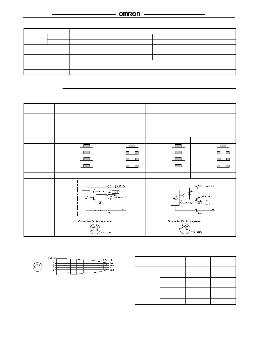
OUTPUT CIRCUITS
Output
configuration
NPN
PNP
Part number
E3G-L11
E3G-L15
E3G-L31
E3G-L35
E3G-L12
E3G-L16
E3G-L32
E3G-L36
Output operation
Light-ON
Dark-ON
Light-ON
Dark-ON
Timing chart
Operate
Reset
(Between brown and black)
Incident
Interrupted
Operation
indicator
(orange)
Output
transistor
Load
(relay)
ON
OFF
ON
OFF
ON
OFF
Operate
Reset
(Between brown and black)
ON
OFF
Incident
Interrupted
Operation
indicator
(orange)
Output
transistor
Load
(relay)
ON
OFF
ON
OFF
Operate
Reset
(Between blue and black)
Incident
Interrupted
Operation
indicator
(orange)
Output
transistor
Load
(relay)
ON
OFF
ON
OFF
ON
OFF
Operate
Reset
(Between blue and black)
ON
OFF
Incident
Interrupted
Operation
indicator
(orange)
Output
transistor
Load
(relay)
ON
OFF
ON
OFF
Mode selector
L-ON (Light-ON)
D-ON (Dark-ON)
L-ON (Light-ON)
D-ON (Dark-ON)
Output circuit
J
CONNECTOR WIRING
XS3F-M421-402-R
XS3F-M421-405-R
XS3F-M422-402-R
XS3F-M422-405-R
Classification
Wire color
Connector
pin number
Use
DC
Brown
1
Power supply
(+ V)
White
2
Pin 2 is not
used.
Blue
3
Power supply
(0 V)
Black
4
Output
E3G-L1/L3
E3G-L1/L3
5
Engineering Data
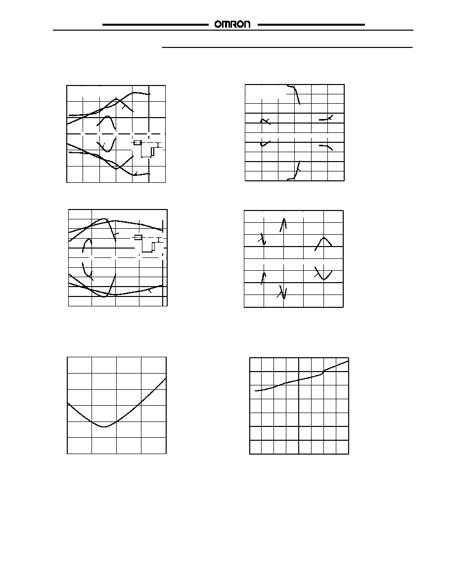
J
OPERATING RANGE
Distance X (mm)
O
per
at
ing
pos
it
ion
Y
(
mm)
2.5
2.0
1.5
1.0
0.5
0
--0.5
--1.0
--1.5
--2.0
--2.5
55
30
35
40
45
50
25
Setting distance: 30 mm,
40 mm,
50 mm
30 mm
40 mm
50 mm
O
per
at
ing
pos
it
ion
Y
(
mm)
3
2
1
0
--1
--2
--3
10
20
30
40
50
60
Settingdistance: 30mm,40mm,50mm
Target object:
Whitepaper50"50mm
40 mm
30 mm
50 mm
X
Y
E3G-L1j (in NORMAL Mode)
E3G-L1j (in ZONE Mode)
Distance X (mm)
Distance X (mm)
4
3
2
1
0
--1
--2
--3
--4
250
50
100
150
200
Setting distance: 50 mm, 100 mm, 200 mm
50 mm
100 mm
200 mm
Distance X (mm)
O
per
at
ing
pos
it
ion
Y
(
mm)
5
4
3
2
1
0
--1
--2
--3
--4
--5
50
100
150
200
Settingdistance: 50mm,100mm,200mm
Targetobject:
Whitepaper 50"50mm
X
Y
100 mm
200 mm
50 mm
E3G-L3j (in ZONE Mode)
E3G-L3j (in NORMAL Mode)
O
per
at
ing
pos
it
ion
Y
(
mm)
S
pot
diamet
er
(
mm)
3
2.5
2
1.5
1
0.5
0
Distance (mm)
30
35
40
45
50
E3G-L1j
J
SPOT DIAMETER VS. SENSING DISTANCE
14
12
10
8
6
4
2
0
40
60
80
100
120
140
160
180
S
pot
diamet
er
(
mm)
200
Distance (mm)
E3G-L3j

E3G-L1/L3
E3G-L1/L3
6
J
ANGLE CHARACTERISTICS
5
4
3
2
1
0
--1
--2
--3
--4
--5
--40
--30
--20
--10
0
10
20
30
40
(Left and Right)
Target object:
White paper 50 " 50 mm
Sensing distance:30 mm
5
4
3
2
1
0
--1
--2
--3
--4
--5
--40
--30
--20
--10
0
10
20
30
40
S
ens
ing
dis
t
anc
e
v
ar
iat
ion
(
%)
Target object:
White paper 50 " 50 mm
Sensing distance:30 mm
Sensing object
Inclination
angle
S
ens
ing
dis
t
anc
e
v
ar
iat
ion
(
%)
Inclination angle " (#)
Sensing object
#"
� "
Inclination
angle
E3G-L1j (Up and Down)
E3G-L1j (Left and Right)
Inclination angle " (#)
(Up and Down)
� "
#"
5
4
3
2
1
0
--1
--2
--3
--4
--5
--40
--30
--20
--10
0
10
20
30
40
5
4
3
2
1
0
--1
--2
--3
--4
--5
--40 --30
--20
--10
0
10
20
30
40
Inclination angle " (#)
S
ens
ing
dis
t
anc
e
v
ar
iat
ion
(
%)
(Left and Right)
Target object:
White paper 50 " 50 mm
Sensing distance:50 mm
Sensing object
Inclination angle " (#)
#"
� "
Inclination
angle
E3G-L1j (Up and Down)
E3G-L1j (Left and Right)
S
ens
ing
dis
t
anc
e
v
ar
iat
ion
(
%)
Target object:
White paper 50 " 50 mm
Sensing distance:50 mm
(Up and Down)
Inclination
angle
#"
� "
Sensing object
S
ens
ing
dis
t
anc
e
v
ar
iat
ion
(
%)
10
8
6
4
2
0
--2
--4
--6
--8
--10
--40
--30
--20
--10
0
10
20
30
40
Target object:
White paper 50 " 50 mm
Sensing distance:50 mm
Sensing object
10
8
6
4
2
0
--2
--4
--6
--8
--10
--40
--30
--20
--10
0
10
20
40
30
S
ens
ing
dis
t
anc
e
v
ar
iat
ion
(
%)
Inclination angle " (#)
Inclination angle " (#)
Target object:
White paper 50 " 50 mm
Sensing distance:50 mm
(Up and Down)
Sensing object
Inclination
angle
(Left and Right)
#"
� "
#"
� "
E3G-L3j (Up and Down)
E3G-L3j (Left and Right)
Inclination
angle

E3G-L1/L3
E3G-L1/L3
7
J
ANGLE CHARACTERISTICS (CONT.)
10
8
6
4
2
0
--2
--4
--6
--8
--10
--40
--30
--20
--10
0
10
20
30
40
10
8
6
4
2
0
--2
--4
--6
--8
--10
--40
--30
--20
--10
0
10
20
30
40
S
ens
ing
dis
t
anc
e
v
ar
iat
ion
(
%)
S
ens
ing
dis
t
anc
e
v
ar
iat
ion
(
%)
Inclination angle " (#)
Inclination angle " (#)
Target object:
White paper 50 " 50 mm
Sensing distance:150 mm
Target object:
White paper 50 " 50 mm
Sensing distance:150 mm
Sensing object
Sensing object
#"
� "
(Up and Down)
Inclination
angle
E3G-L3j (Up and Down)
E3G-L3j (Left and Right)
(Left and Right)
Inclination
angle
#"
� "
J
TARGET OBJECT SIZE VS. SETTING DISTANCE
0.5
0.4
0.3
0.2
0.1
0
30
35
40
45
50
Target object:
White paper
Setting distance: 50 mm
Distance (mm)
E3G-L1j
Min.
s
ens
ing
objec
t
d
ia.
(
mm)
2.5
2
1.5
1
0.5
0
40
60
80
100
120
140
160
180 200
Target object:
White paper
Setting distance: 200 mm
Distance (mm)
E3G-L3j
Min.
s
ens
ing
objec
t
d
ia.
(
mm)
White paper
60
50
40
30
20
10
0
Setting distance: 30 mm
S
ens
ing
dis
t
anc
e
(
mm)
18 mm
31 mm
30 mm
20 mm
1 mm
50 mm
16 mm
51 mm
White paper
Black paper
Black paper
Setting distance: 50 mm
J
CLOSE-RANGE CHARACTERISTICS
E3G-L1j
Material
150
100
50
0
51 mm
48.5 mm
202 mm
178 mm
29 mm
20 mm
0 mm
28.5 mm
250
200
White paper
Material
S
ens
ing
dis
t
anc
e
(
mm)
White paper
Black paper
Black paper
Setting distance: 50 mm
Setting distance: 200 mm
E3G-L3j

E3G-L1/L3
E3G-L1/L3
8
J
SENSING DISTANCE VS. SENSING OBJECT MATERIAL
35
30
25
20
15
10
5
0
45
40
35
30
25
20
15
10
5
0
White
paper
Material
S
ens
ing
dis
t
anc
e
(
mm)
Black
paper
Black
rubber
Fiberboard
Veneer
Mirror
White
paper
Black
paper
Black
rubber
Fiberboard
Veneer
Mirror
S
ens
ing
dis
t
anc
e
(
mm)
Material
E3G-L1V (at 30 mm Setting Distance)
E3G-L1V (at 40 mm Setting Distance)
60
50
40
30
20
10
0
White
paper
Black
paper
Black
rubber
Fiberboard
Veneer
Mirror
S
ens
ing
dis
t
anc
e
(
mm)
Material
E3G-L1V (at 50 mm Setting Distance)
60
50
40
30
20
10
0
White
paper
Black
paper
Black
rubber
Fiberboard
Veneer
Mirror
S
ens
ing
dis
t
anc
e
(
mm)
Material
E3G-L3j (at 50 mm Setting Distance)
180
150
120
90
60
30
0
120
100
80
60
40
20
0
White
paper
Black
paper
Black
rubber
Fiberboard
Veneer
Mirror
S
ens
ing
dis
t
anc
e
(
mm)
S
ens
ing
dis
t
anc
e
(
mm)
White
paper
Black
paper
Black
rubber
Fiberboard
Veneer
Mirror
Material
E3G-L3j (at 150 mm Setting Distance)
E3G-L3j (at 100 mm Setting Distance)
Material

E3G-L1/L3
E3G-L1/L3
9
Nomenclature
UP/DOWN selector
Selects the switching
direction at threshold.
Operation indicator (Orange)
ON when output is ON.
Distance indicator (Green)
Display the distance relative
to the threshold.
Threshold indicator (Red)
Indicates threshold level.
For teaching or for threshold
adjustment
Operation mode selector
Selects L-ON or D-ON.
NORMAL/ZONE selector
Selects the detection mode.
Mode selector
Selects the mode.
NORM L
ZONE D
ADJ
FAR
SET
TEACH
OUT
RUN
SET button
NEAR
Installation
J
MOUNTING DIRECTIONS
Non-shiny Targets
Make sure the sensing side of the sensor is parallel with the
surface of the target object. Do not tilt the sensor towards the
target object.
Sensing side
Surface of target object
Shiny Targets
If the target object has a glossy surface, incline the sensor by 5#
to 10# as shown below, provided that the sensor is not influenced
by any background objects.
Glossy object
If there is a mirror--like object below the sensor, the sensor may
not be in stable operation. Tilt the sensor or keep the sensor far
enough away from the mirror--like object to avoid interfering
reflections as shown below.
Target
object
Mirror--like object
Make sure not to install the sensor in the incorrect direction.
Refer to the following.
Target object
Moving direction
Target object
Target object
Moving
direction
Moving direction
Correct
Incorrect
Install the sensor as shown in the following if the target object
greatly differs in color or material.
Moving direction
Moving direction
Correct
Incorrect

E3G-L1/L3
E3G-L1/L3
10
J
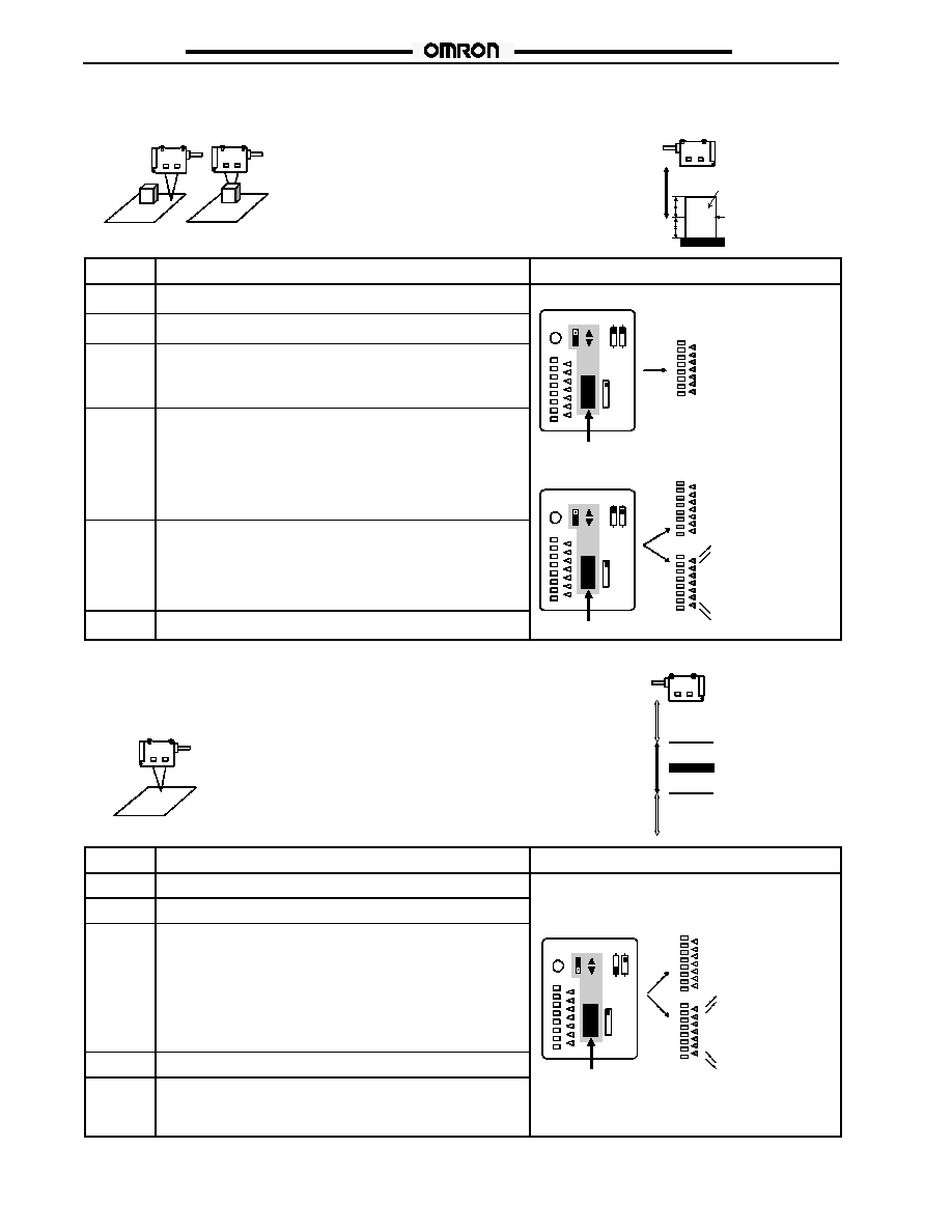
ADJUSTMENTS
If the sensor is not in stable operation due to color differences, make a fine adjustment of the threshold level and confirm that the sensor
operates in stable state. Refer to Manual Teaching (Fine Distance Setting.
Adjustment Steps
1
Install, wire, and turn on the sensor.
2
Perform distance setting (teaching). Refer to Distance Setting (Teaching) below.
3
Make a fine adjustment of the threshold, if necessary.
Refer to Manual Teaching (Fine Distance Setting)
4
Check that the mode selector is set to RUN.
Distance Setting (Teaching)
Select the most appropriate teaching method in reference to the following descriptions.
1
2
3
Application
$
Teaching without sensing
objects (i.e., Teaching the
background).
$
$
Detection of slight differences
in surface level.
Setting a threshold in the
middle between the
background and sensing object
for operation.
$
Detection of glossy objects in
front of the background.
Teaching
1
Normal one-point teaching
2
Normal two-point teaching
3
Zone one-point teaching
Setting method
Press the TEACH button with
the background object.
present.
Sensor
Background
Press the TEACH button with
the background object and
with the target object.
Sensor
Background
Background
Sensor
Object
Press the TEACH button with
the background object
(conveyor, etc.).
Background
Sensor
Set threshold
Threshold (a) is set immediately in
front of the background.
Threshold (a) is set approximately
in the middle between the
background and target object.
A pair of thresholds, (a) and (b),
are set.
Output ON range
The output is ON between the
sensor and La.
E3G-L
The output is ON between the
sensor and La.
E3G-L
Object
The output is ON between La and
Lb.
E3G-L
ON
OFF
D-ON L-ON
Output ON range
Threshold a (La)
Background
ON
ON
Threshold a (La)
Background
Object
Threshold a (La)
ON
Background
Threshold b (Lb)
ON
OFF
OFF
La: Distance equivalent to threshold (a)
Lb: Distance equivalent to threshold (b)
The following settings are also possible:
Setting the maximum sensing distance of the sensor: Maximum distance setting.
Setting the minimum differential travel of the sensor: Minimum distance setting.
Distance from sensor to background must not exceed the values shown below during
normal one-point or zone one-point teaching.
Part number
Distance from sensor to background
E3G-L1j
32 mm (1.26 in) min.
E3G-L3j
55 mm (2.17 in) min.
Maximum sensing distance of E3G-L3 type may differ by color of the target object
when setting distance is more than 150 mm (5.91 in).
Confirm the operation of the sensor before actual operation.

E3G-L1/L3
E3G-L1/L3
11
J
ADJUSTMENTS (CONT.)
Normal One-point Teaching
Sensor
Background
Threshold a (La)
E3G-L
Background
ON
Procedure
Operation
Panel status
1
Set the mode selector to TEACH.
NORM L
2
Set the NORMAL/ZONE mode selector to NORMAL.
OUT
NORM L
3
Press the SET button with the background. The threshold
indicator (red) will turn ON.
Threshold indicator
(red) turns ON.
TEACH
ZONE D
NEAR
SET
4
Set the mode selector to RUN.
(red) turns ON.
ADJ
5
Set to L-ON or D-ON mode with the operation mode selector.
L-ON: Output ON between background and sensor.
D-ON: Output OFF between background and sensor.
Press
RUN
FAR
Application Example 1
Adjusting the sensor differential travel to the minimum distance.
OUT
NORM L
1
Set the mode selector to TEACH.
TEACH
ZONE D
NEAR
SET
2
Set the NORMAL/ZONE mode selector to NORMAL.
ADJ
TEACH
SET
3
Set the UP/DOWN selector to down.
RUN
FAR
4
Press the SET button for 3 s or more. The threshold indicator
(red) will turn ON.
Press
Press the SET
button for 3 s
Set the
mode selec-
5
The distance indicator (green) will turn ON. This means that
teaching is successful. Set the mode selector to RUN to
complete the teaching operation.
button for 3 s
or more.
mode selec-
tor to RUN.
Threshold indicator
Distance indicator
6
Set to L-ON or D-ON mode with the operation mode selector.
Threshold indicator
(red) turns ON.
Distance indicator
(green) turns ON.
Application Example 2
Setting the sensor to the maximum distance.
OUT
NORM L
1
Set the mode selector to TEACH.
ZONE D
NEAR
SET
2
Set the NORMAL/ZONE mode selector to NORMAL.
ADJ
TEACH
SET
3
Set the UP/DOWN selector to up.
RUN
ADJ
FAR
4
Press the SET button for 3 s or more. The threshold indicator
(red) will turn ON.
Press
Press the SET
button for 3 s
Set the mode
selector to
FAR
5
The distance indicator (green) will turn ON. This means that
teaching is successful. Set the mode selector to RUN to
complete the teaching operation.
button for 3 s
or more.
selector to
RUN.
6
Set to L-ON or D-ON mode with the operation mode selector.
Threshold indicator
(red) turns ON.
Distance indicator
(green) turns ON.
La: Distance equivalent to threshold (a)
E3G-L1/L3
E3G-L1/L3
12
J
ADJUSTMENTS (CONT.)
Normal Two-point Teaching
Sensor
Background
Background
Sensor
Object
ON
E3G-L
Threshold a (La)
Background
Object
Procedure
Operation
Panel status
1
Set the mode selector to TEACH.
Object
2
Set the NORMAL/ZONE mode selector to NORMAL.
OUT
NORM L
3
Press the SET button with a sensing object located at sensing
position.
The threshold indicator (red) will turn ON.
Threshold indicator
(red) turns ON.
ADJ
TEACH
ZONE D
NEAR
SET
4
Move the sensing object and press the SET button with the
background.
If the teaching is successful, the distance indicator (green) will
turn ON.
If the teaching is not successful, the threshold indicator (red) will
start to flash.
Background
Press
Distance indicator
(green) turns ON.
RUN
FAR
OUT
NORM L
5
If the teaching is successful, set the mode selector to RUN to
complete the teaching operation.
If the teaching is not successful, change the position of the object
and setting distance that have been set and repeat the procedure
from step 3 above.
OK
NG
(green) turns ON.
Threshold indicator
(red) starts to flash.
RUN
ADJ
TEACH
ZONE D
NEAR
FAR
SET
6
Set to L-ON or D-ON mode with the operation mode selector.
Press
FAR
La: Distance equivalent to threshold (a)
Sensor
Background
OFF
E3G-L
Threshold a (La)
OFF
ON
Background
Threshold b (Lb)
J
ADJUSTMENTS (CONT.)
Zone One-point Teaching
Procedure
Operation
Panel status
1
Set the mode selector to TEACH.
2
Set the NORMAL/ZONE mode selector to ZONE.
3
Press the SET button with the background.
All threshold indicators (Red) will turn ON while the SET button is
pressed. When the SET button is released:
$ If the teaching is successful, the distance indicator (green) will
turn ON.
$ If the teaching is not successful, the threshold indicator (red) will
start to flash.
OK
NG
Distance indicator
(green) turns ON.
Threshold indicator
(red) starts to flash.
OUT
RUN
ADJ
TEACH
ZONE D
NORM L
NEAR
FAR
SET
4
Set the mode selector to RUN.
P
FAR
5
Set to L-ON or D-ON mode with the operation mode selector.
L-ON: Output ON with the background.
D-ON: Output OFF with the background.
Press
La: Distance equivalent to threshold (a)
E3G-L1/L3
E3G-L1/L3
13
J
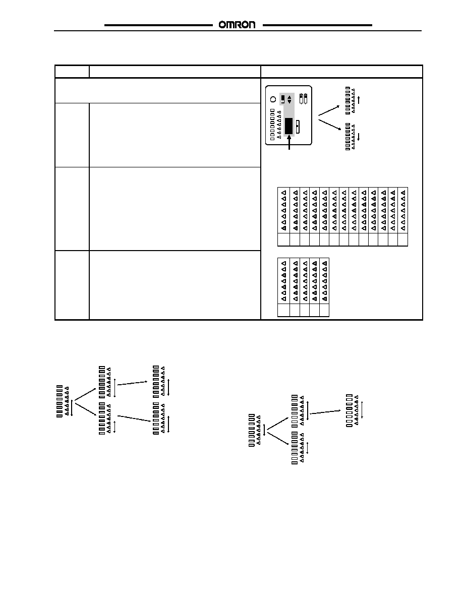
ADJUSTMENTS (CONT.)
Manual Teaching (Fine Distance Setting)
Procedure
Operation
Panel status
Fine adjustment of the threshold is possible after teaching.
SET pressed
with UP/
DOWN se-
lector set to
Threshold increases
OUT
NORM L
1
Set the mode selector to ADJ.
lector set to
UP.
SET pressed
with UP/
DOWN se-
lector set to
DOWN.
Threshold decreases
Threshold Indicator Display During
RUN
ADJ
TEACH
ZONE D
NEAR
FAR
SET
Press
2
Set the adjustment direction in the ADJ mode with the
UP/DOWN selector.
The threshold changes each time the SET button is pressed.
The setting can be made in up to 13 levels (for normal
one--point or two--point teaching).
Threshold Indicator Display During
Distance Adjustment
Fi
dj t
t l
l f
t
hi
Max. 13 adjustment levels for normal teaching
1
2
3
4
5
6
7
8
9
10
13
12
11
3
After the adjustment is complete, set the mode selector to
RUN.
Five adjustment levels for zone teaching
1
2
3
4
5
Threshold and Distance Indicator Displays
Display for Distance Setting with Normal One-point or Two-
point Teaching
UP
UP
Control output: ON
DOWN
DOWN
Control output: ON
The distance indicators show the distance level. The distance
indicators show distances relative to the threshold.
The threshold can be shifted using the UP/DOWN selector and
SET button. The differential travel is fixed.
Display for Distance Setting with Zone Teaching
The distance indicators show the current distance band. The
distance indicators show distances relative to the threshold.
The ON range can be shifted using the UP/DOWN selector and
SET button. The differential travel is fixed.
UP
UP
Control output: ON
DOWN
(No change)
E3G-L1/L3
E3G-L1/L3
14
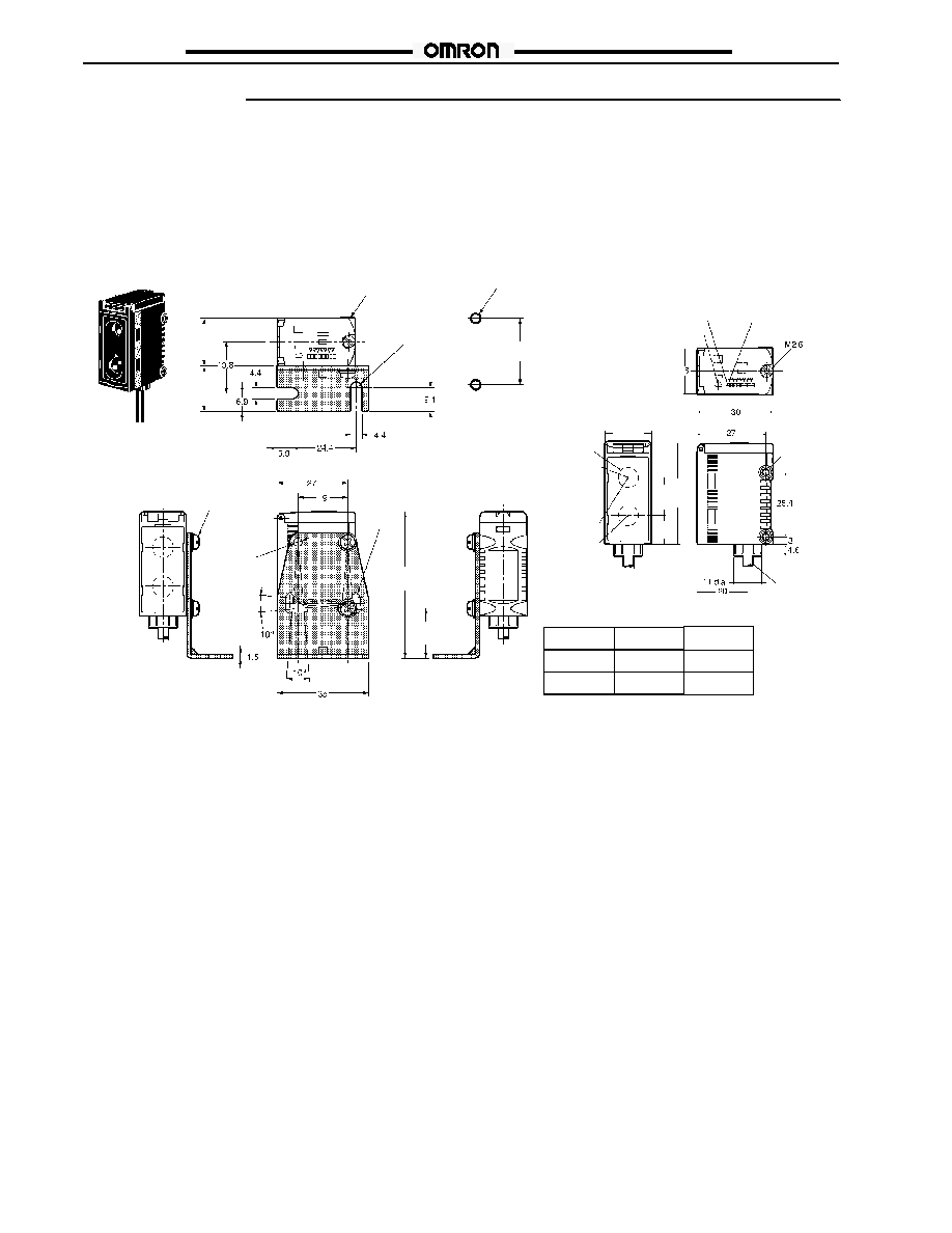
Dimensions
Unit: mm (inch)
J
SENSORS
Preleaded Models
E3G-L11/L31
Shown with mounting bracket E39-L139 (included)
E3G-L12/L32
Two, M4
Mounting bracket can
be attached to this side.
Two, R2.2
25.4
(1.00)
18.4
(0.72)
17.5
(0.69)
Two,
3.2 dia.
Two, M3
Six,
R1.6
56.1
(2.21)
19.1
(0.75)
Operation indicator
(orange)
Distance
indicator
(green)
Threshold
indicator (red)
Two, M3
through holes
18.4
(0.72)
Two, 8-dia. lens
Emitter
Optical
axis
Receiver
Vinyl--insulated
round cable
with three
conductors
4 OD (18 x
0.12 dia.)
40
(1.57)
A
B
Mounting holes
Model
E3G--L1j
E3G--L3j
14.5 (0.57)
16.0 (0.63)
A
10.35 (0.41)
B
Model
E3G-L1j
E3G-L3j
14.5 (0.57)
16.0 (0.63)
A
11.88 (0.47)
B
See table
below.
E3G-L1/L3
E3G-L1/L3
15
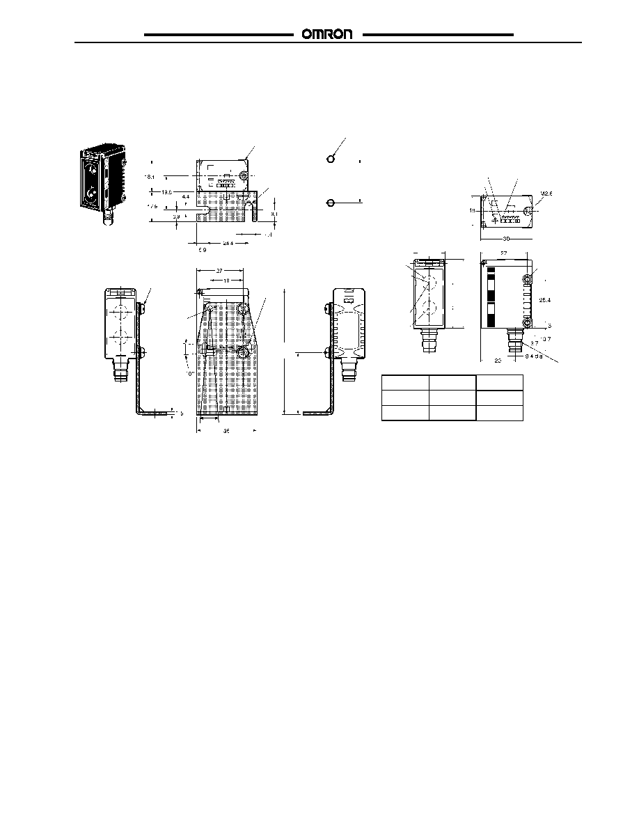
Connector Models
E3G-L15/L35
Shown with mounting bracket E39-L140 (included)
E3G-L16/L36
A
B
Mounting holes
Distance indicator
(green)
Threshold indicator
(red)
Operation indicator
(orange)
Mounting bracket can
be attached to here.
Two, M3
Six, R1.6
Two, 3.2--dia.
Two, M3
through holes
Two, 8-dia. lens
Emitter
Optical axis
Receiver
Two, R2.2
M8 connector
Two, M4
10_
40
(1.57)
18.4
(0.72)
25.4
(1.00)
Model
E3G-L1j
E3G-L3j
14.5 (0.57)
16.0 (0.63)
A
11.88 (0.47)
10.35 (0.41)
B
See table
below.
73.1
(2.88)
36.1
(1.42)

E3G-L1/L3
E3G-L1/L3
16
J
MOUNTING BRACKETS
E39-L139
Material: Stainless steel (SUS304)
10#
Note: Provided with E3G-Lj1/-Lj2
E39-L140
Material: Stainless steel (SUS304)
10#
Note: Provided with E3G-Lj5/-Lj6
J
CONNECTOR CORDSETS
Straight
XS3F-M421-402-R (L = 2 m)
XS3F-M421-405-R (L = 5 m)
4 dia.
Right Angle
XS3F-M422-402-R (L = 2 m)
XS3F-M422-405-R (L = 5 m)

E3G-L1/L3
E3G-L1/L3
17
Precautions
J
DESIGNING
High-voltage Lines
Do not place sensor power supply or signal lines within the same
conduit as high-voltage power lines.
Voltage Ratings
Do not exceed rated supply voltage, ripple percent (for DC
models), or load current limits.
Ambient Lighting
Do not install the sensor in direct sunlight or other sources of
strong ambient light.
Environmental Conditions
Do not install the sensor in areas
$
With high humidity, or where condensation would result
$
With corrosive gas.
$
With high vibration or shock.
Power Supply
If a switching power supply is used, or when using an inverter or
servomotor, you must ground the FG (frame ground) and G
(ground) terminals on the power supply for proper operation and
to avoid damaging the sensor.
Water Exposure
Although conforming to IP67, do not use the sensor where it may
be immsersed, is outdoors, or is exposed to rain.
To ensure the water resistance of the sensor, tighten the screws
of the operation panel cover to a torque of 0.2 to 0.3 N S m.
Cable
$
The bending radius of the cable should be at least 25 mm.
$
When using extended power and signal cable, total length
must not exceed 100 m, with a minimum wire size of
0.3 mm
2
(22 AWG).
$
Do not apply tensile force exceeding 50 N to cable (pre-
leaded and connector models).
Avoiding Malfunctions
If using the photoelectric sensor with an inverter or servomotor,
be sure to ground the FG (frame ground) and G (ground)
terminals, otherwise the sensor may malfunction.
Proper Mounting Screws
Use M3 screws and washers to mount the sensor and bracket.
Mechanical Shock
Avoid mechanical shock during installation which may amage the
housing (see Shock specifications)
Short--circuit Protection
If the load short--circuits, the output will be turned off. Disconnect
power and check the wiring. After correcting the shorted
condition, turn power back on. The sensor will reset the
short-circuit protection function. The short-circuit protection is
activated when the current flow is at least 2.4 times the rated
load current. When using an inductive load, the inrush current
must not exceed this factor.
Connector
$
When connecting or disconnecting the connector, hold the
connector cover to avoid tension on the housoing.
$
Tighten the connector by hand only. Do not use tools which
may damage the connector.
$
Always disconnect power before connecting or disconnecting
the connector.
$
Be sure that the connector is tightened securely. The sesnor
enclosure rating may be reduced or the connector may get
loosened.
J
MAINTENANCE AND INSPECTION
Cleaning
$
Solvents damage the casing of the sensor. Do not use
solvents to clean the sensor.
EEPROM Writing Error
$
If a teaching data error occurs with the operation indicator
flashing due to a power failure or static noise, perform the
teaching operation of the sensor again.

E3G-L1/L3
E3G-L1/L3
Cat. No. CEDSAX4
11/01
Specifications subject to change without notice.
Printed in U.S.A.
OMRON ELECTRONICS LLC
One East Commerce Drive
Schaumburg, IL 60173
NOTE: DIMENSIONS SHOWN ARE IN MILLIMETERS. To convert millimeters to inches divide by 25.4.
1-800-55-OMRON
OMRON CANADA, INC.
885 Milner Avenue
Scarborough, Ontario M1B 5V8
416-286-6465
R
OMRON ON--LINE
Global -- http://www.omron.com
USA -- http://www.omron.com/oei
Canada -- http://www.omron.com/oci