Document Outline
- Front Page
- Ordering Information
- Specifications
- Nomenclature
- Operation
- Dimensions
- MiniChange Connector
- Precautions
- Contacting Omron

R
General-Purpose Fiber-optic Sensor
E3JU-X/XR
Compact Limit Switch Style with
Universal Power Supply
H
FET output allows for solid state
switching of AC or DC
H
Universal AC/DC power supply
H
Choose cable or connector types
H
Sensitivity adjustment standard on all
models
H
Wide selection of timing options
H
UL/CE/CSA approved
H
NEMA 4X, IP66 rated
Ordering Information
J
AMPLIFIERS
Light source
Infrared LED
Red LED
Fiber-optic cable attachment
E32-series large diameter fiber (4.75 mm)
E32-series small diameter fiber (2.2 mm)
Output
Connection
Timer
Part number
Relay
300-V cable
No
E3JU-XM4-3
E3JU--XRM4-3
y
600-V cable
E3JU-XM4-6
E3JU--XRM4-6
300-V cable
Yes
E3JU-XM4T-3
E3JU-XRM4T-3
600-V cable
E3JU-XM4T-6
E3JU-XRM4T-6
FET
300-V cable
No
E3JU-XP4-3
E3JU-XRP4-3
600-V cable
E3JU-XP4-6
E3JU-XRP4-6
300-V cable
Yes
E3JU-XP4T-3
E3JU-XRP4T-3
600-V cable
E3JU-XP4T-6
E3JU-XRP4T-6
Relay
MiniChangeR
No
E3JU-XM4-MN1
E3JU-XRM4-MN1
y
C a ge
Connector
Yes
E3JU-XM4T-MN1
E3JU-XRM4T-MN1
FET
MiniChangeR
No
E3JU-XP4-MN1
E3JU-XRP4-MN1
C a ge
Connector
Yes
E3JU-XP4T-MN1
E3JU-XRP4T-MN1
J
ACCESSORIES
Description
Part number
Mounting bracket
E39-LU1
E3JU-X/XR
E3JU-X/XR
2
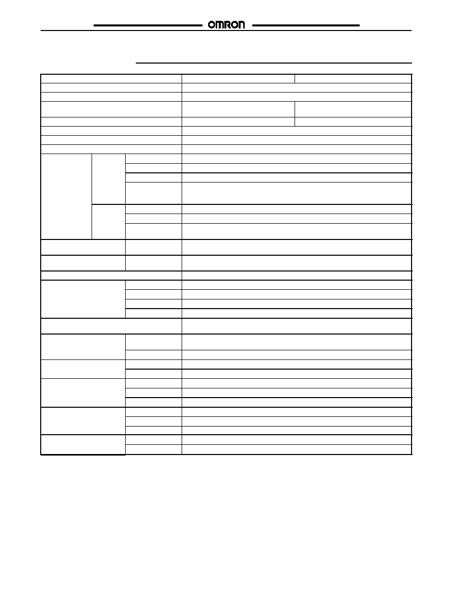
Specifications
Part number
E3JU-XRj4j-j
E3JU-Xj4j-j
Supply voltage
24 to 240 VAC !10%, 50/60 Hz; 12 to 240 VDC, 10% max. peak-to-peak ripple
Power consumption (up to 264 VDC)
Contact relay type 4.0 W max., solid state relay type 3.5 W max.
Required fiber-optic cables
E32-series (2.2 mm dia. or 1 mm dia.
with E39-F9) (See Note.)
E32-UjB series (4.75 mm dia.)
Light source
Red LED (660 mm)
Infrared LED (950 mm)
Operation mode
Light-ON/Dark-ON, switch selectable
Sensitivity
Adjustable
Mutual interference protection
Provided
Contact output
Contact
l
Type
SPDT relay
relay
Max. load
3 A, 250 VAC; 30 VDC rated (p.f.=1)
Min. load
10 mA, 5 VDC minimum
Response time
Models without timer and models set to NO Timer: 12 ms ON (6 ms typ.),
12 ms OFF (5 ms typ.);
Models with timer: 0.1 to 10 sec (adjustable).
Solid
t t
Type
Power MOSFET relay
state
relay
Max. load
400 mA AC/DC (600 mA up to 40"C), 240 VAC., 100 VDC rated
relay
Response time
Models without timer and timer models set to No Timer: 8 ms ON, 12 ms OFF max.
Models with timer: 0.1 to 10 sec (adjustable).
Timer functions
(models with timer)
Type/range
ON-delay, OFF-delay, ON/OFF delay, one-shot, delayed one-shot; switch select-
able/0.1 to 10 seconds
Circuit protection
Output
short-circuit
Not provided
Indicators
Light incident (red LED), output operation (yellow LED), stability (green LED)
Materials
Case
Plastic ABS/PC
Holder
Plastic ABS/PC
Clamp
Plastic POM
Cover
Plastic PC
Mounting
Two M5 front-mounting through holes. M30 externally threaded base and 1/2-14
NPSM internal threads for cable type: conduit torque not to exceed 100 in-lbs.
Connections
Prewired
(--6) 600 V-rated, AWG 20: 4-wire cable, AWG 21: 5-wire cable or
(--3) 300 V-rated, AWG 22: 4-wire, 5-wire cables
Connector
MiniChangeR type connector: 4 and 5 pins
Weight
Cable type
(--6): 305 g (10.68 oz); (--3): 225 g (7.88 oz)
g
Connector type
135 g (4.73 oz)
Enclosure ratings
UL
Type 1
g
NEMA
1, 2, 3, 4X, 5, 12
IEC 144
IP66
Approvals
UL
Listing E41515
pp
CSA
Certification LR45951
CE
IEC947-5-2
Ambient temperature
Operating
-25"C to 55"C (-13"F to 131"F)
Storage
-40"C to 70"C (-40"F to 158"F)
Note: Must use fiber that can be inserted 15 mm into amplifier to meet sensing distance specification.

E3JU-X/XR
E3JU-X/XR
3
Nomenclature
J
SENSOR WITHOUT TIMER
E3JU-
jjj
4-
j
J
SENSOR WITH TIMER
E3JU-
jjj
4T-
j
E3JU-X/XR
E3JU-X/XR
4
Operation
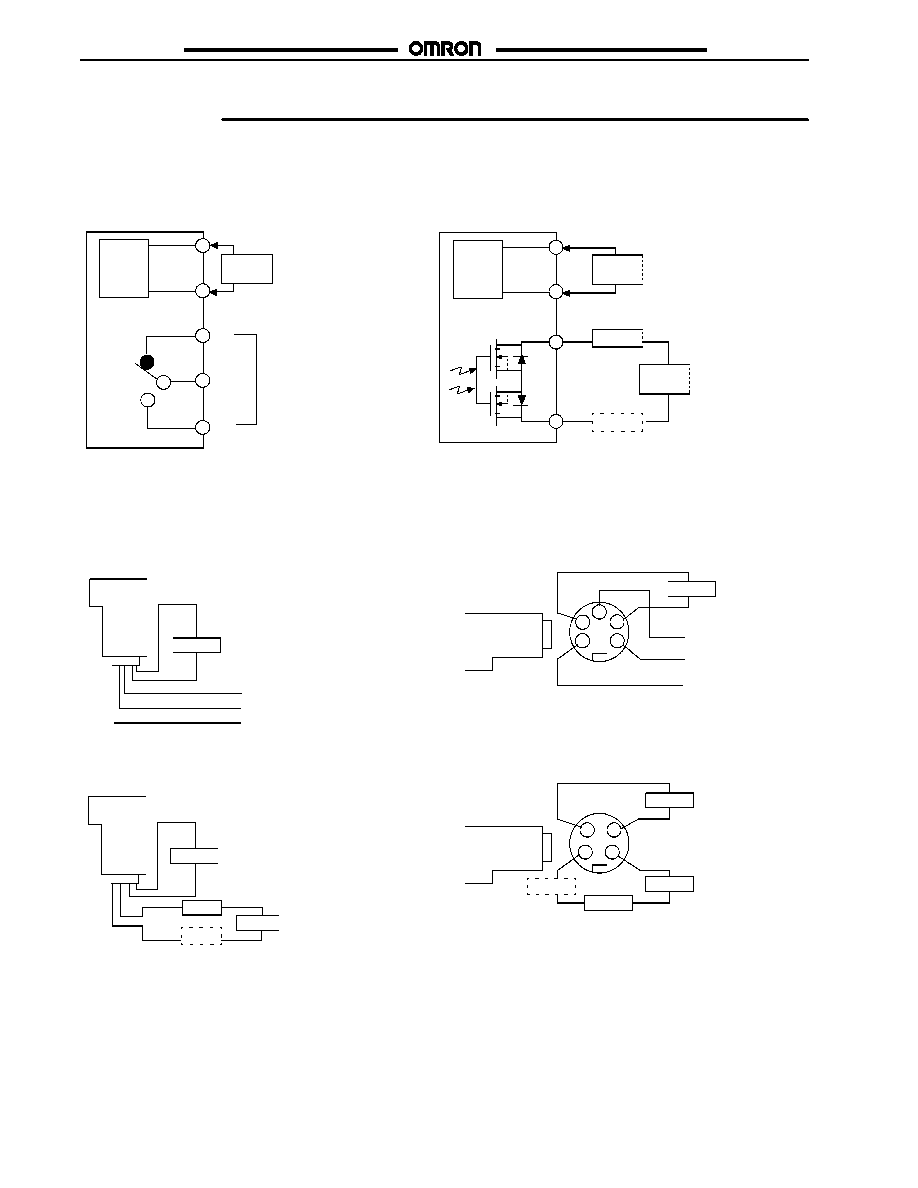
J
OUTPUT CIRCUIT DIAGRAMS
Solid State Relay Output Types
E3JU-jjPjj-j
Relay Output Types
E3JU-jjMjj-j
Main
circuit
Load*
Power
supply
Main
circuit
Load*
Power
supply
Power
supply
COM
NO
NC
Relay output
24 to 240 VAC
12 to 240 VDC
(50/60 Hz AC)
Either polarity
250 VAC, 3 A rated
5 VDC, 10 mA min.
24 to 240 VAC
12 to 240 VDC
(50/60 Hz AC)
Either polarity
0.1 to 400 mA
* Load can be hooked up on either
side of the power supply.
Line voltage
5 to 240 VAC
5 to 100 VDC
Either polarity
Optically
isolated
J
CONNECTIONS
Relay Output Types
E3JU-jjMjj-3
E3JU-jjMjj-6
Solid State Relay Output Types
E3JU-jjPjj-3
E3JU-jjPjj-6
Brown
Blue
Brown
Blue
Power
COM
NO
NC
Power
White
Load
Black
Power
Relay Output Types
E3JU-jjMjj-MN1
Solid State Relay Output Types
E3JU-jjPjj-MN1
COM
NO
NC
Power
2
1
5
4
3
Power
2
1
4
3
24 to 240 VAC
12 to 240 VDC
24 to 240 VAC
12 to 240 VDC
24 to 240 VAC
12 to 240 VDC
24 to 240 VAC
12 to 240 VDC
* Load can be hooked up on either side
of the power supply.
Load*
Load
Gray
Black
White
Power
Load*
E3JU-X/XR
E3JU-X/XR
5
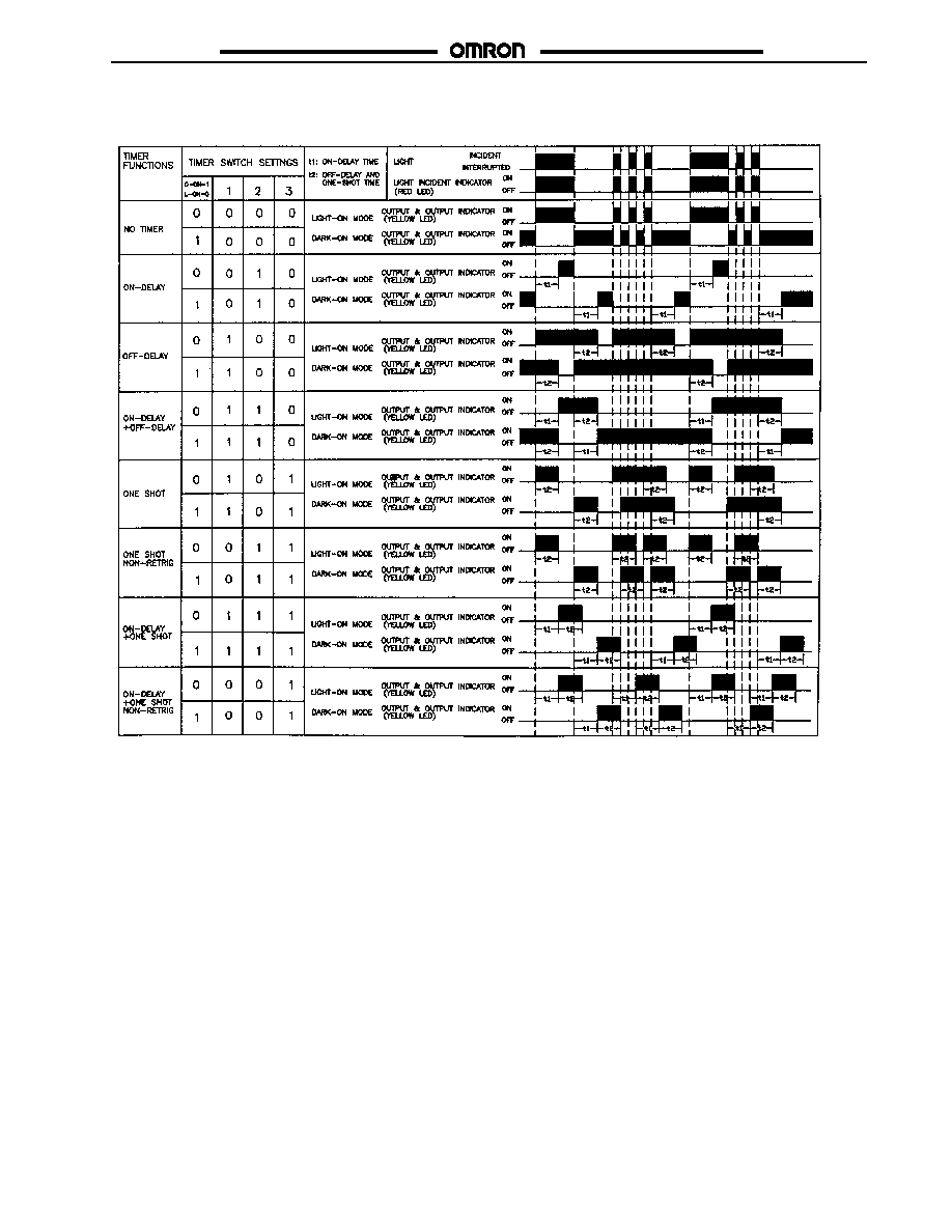
J
TIMING CHART
E3JU-X/XR
E3JU-X/XR
6
J
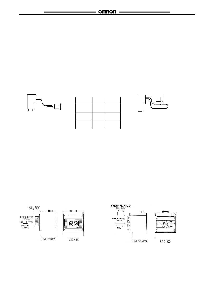
SENSITIVITY ADJUSTMENT
#
Place the target object in the desired position for
detection and set the sensitivity adjustment to maximum.
#
Maximum stability is achieved by varying both horizontal
and vertical alignment of the fiber until it is in the center of
a range in which both the LIGHT (Red) and STABILITY
(Green) indicators illuminate (Light-ON mode).
#
Remove the object and ensure the LIGHT indicator turns
off and the STABILITY indicator illuminates. If the LIGHT
indicator does not turn off, decrease the sensitivity and
check that there is no other object in line with the fiber.
#
Ensure the STABILITY indicator illuminates in both
detecting and non-detecting states. (Refer to table below.)
#
Turn the sensitivity adjustment to maximum.
#
Position the fiber optic cable ends opposite each other and
adjust the horizontal and vertical alignment until the
STABILITY indicator (Green), LIGHT indicator (Red), and
OUTPUT indicator (Yellow) turn on (Light-ON mode).
#
Once the desired position is set, introduce the object to the
beam pattern and ensure that the LIGHT and OUTPUT
indicators turn off and the STABILITY indicator illuminates.
#
If the LIGHT and OUTPUT indicators do not turn off,
decrease the sensitivity until the desired result is achieved.
#
Ensure that the STABILITY indicator illuminates in both
detecting and non-detecting states. (Refer to table below.)
Through-beam
Diffuse
Object
Object
Indicators
Light
(Red)
ON
OFF
Incident
Stability
(Green)
ON
ON
OFF
Output
(Yellow)
Interrupt
ON
LED Status (Light-ON Mode)
Diffuse Reflective Type
Through-beam Type
J
FIBER CONNECTION AND DISCONNECTION
#
Uses E32 series fiber-optic cable with grooved tip
(4.75 mm diameter).
#
Make sure the clamp is raised in the unlocked position.
#
Firmly insert the fiber-optic cable tips into the amplifier.
#
Move the clamp down to the locked position (the ridges in
the clamp should slide into the grooves of the tips and
hold the fiber cables in place).
#
To remove the fiber cables, raise the clamp to the
unlocked position and carefully pull the fiber cables out
of the unit.
E3JU-Xj4j-j
#
Uses E32 series fiber-optic cable (2.2 mm diameter or
1 mm diameter with E39-F9 adapter).
#
Make sure the clamp is placed in the unlocked position
#
Carefully insert the fiber cable into the amplifier, approxi-
mately 14.0 mm (0.55 in).
Caution: The amplifier may be damaged if excessive force is
used when inserting the fiber cables.
#
Rotate the clamp to the locked position to secure the fiber
cables in place.
#
To remove the fiber cables, rotate the clamp to the
unlocked position and carefully pull the fiber cables out
of the unit.
E3JU-XRj4j-j

E3JU-X/XR
E3JU-X/XR
7
Dimensions
Unit: mm (inch)
J
AMPLIFIERS
E3JU-XRjjj-j
E3JU-Xjjj-j
E3JU-X/XR
E3JU-X/XR
8
J
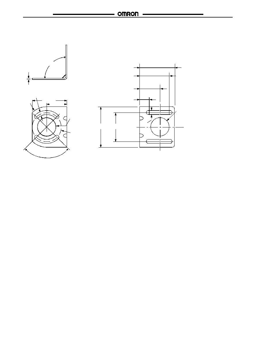
MOUNTING BRACKET
E39-LU1 (Order Separately)
90"
61.0 (2.4)
35.6 (1.4)
30.7
(1.21) dia.
71.1 (2.8)
50.8 (2.0)
90"!0.5"
3.0 (0.119)
61.0 (2.4)
7.1
(0.28)
7.1 (0.28)
35.6
(1.4)
rad.
30.7
(1.21) dia.
50.8
(2.00) dia.
53.3 (2.1)
35.6 (1.4)
15.2 (0.6)
E3JU-X/XR
E3JU-X/XR
9
MiniChange Connector
R
J
BRAD HARRISON MINICHANGE
R
CONNECTOR CABLES
Connector type
Applicable sensors
Length
Straight
Right angle
5-pole female connectors
E3JU-jM4j-MN1
6 foot
41307
41307-90
p
3JU j
j
12 foot
41308
41308-90
20 foot
41322
41322-90
4-pole female connectors
E3JU-jP4j-MN1
6 foot
41108
41111-90
p
3JU j
j
12 foot
41109
41112-90
20 foot
41177
41177-90
Note: The above part numbers represent Brad Harrison (Daniel Woodhead) part numbers not Omron part numbers. Please contact your
local Omron distributor for future availability by Omron and other equivalent Connector Cables.
Precautions
WARNING
These photoelectric sensors should not be used in personal
safety applications. Using the sensor as a safety device may
cause an unsafe condition that could lead to serious injury or
death.
CAUTION
Cover Screw Torque:
The torque of the cover screw must not exceed 3.5 kgScm
(3 inSlb). Over-torquing twill cause the plastic parts to crack.
J
HIGH-VOLTAGE LINES
Do not place sensor power supply or signal lines within the same
conduit as high-voltage power lines.
J
VOLTAGE RATINGS
Do not exceed rated supply voltage, ripple percent (for DC
models), or load current limits.
J
AMBIENT LIGHTING
Do not install sensor in direct sunlight, or other sources of strong
ambient light.
J
ENVIRONMENTAL CONDITIONS
Do NOT install sensor in areas with any of these conditions:
#
High humidity, or where condensation would result.
#
Corrosive gas.
#
High vibration or shock.
J
POWER SUPPLY
If a switching power supply is used, or when using with an
inverter or servomotor, ground the FG (frame ground) and
G (ground) terminals on the power supply for proper operation to
avoid damaging the sensor.
J
WATER EXPOSURE
Do not use the sensor where it may be immersed, is outdoors, or
exposed to rain.
J
PROPER MOUNTING SCREWS
Use M5 screws and washers to mount sensor and bracket.
J
MECHANICAL SHOCK
Avoid mechanical shock during installation which may damage
the housing (see mechanical shock specifications).
J
CONNECTOR
#
When connecting or disconnecting the connector, hold the
connector cover to avoid tension on housing.
#
Tighten connector only by hand. Do not use tools, which may
damage the connector.
#
Always disconnect power before connecting or disconnecting
the connector.
#
Be sure that the connector is tightened securely. If this is not
done, the sensor enclosure rating may be reduced, or the
connector may loosen and affect the enclosure rating.
!
!
C:/CEDSAX4
E3JU-X/XR
E3JU-X/XR
Cat. No. E01SAD3 04/02 Specifications subject to change without notice. Printed in U.S.A.
OMRON ELECTRONICS LLC
One East Commerce Drive
Schaumburg, IL 60173
NOTE: DIMENSIONS SHOWN ARE IN MILLIMETERS. To convert millimeters to inches divide by 25.4.
1-800-55-OMRON
OMRON CANADA, INC.
885 Milner Avenue
Scarborough, Ontario M1B 5V8
416-286-6465
R
OMRON ON--LINE
Global -- http://www.omron.com
USA -- http://www.omron.com/oei
Canada -- http://www.omron.com/oci