Document Outline
- Front Page
- Ordering Information
- Specifications
- Dimensions
- Operation
- Precautions
- Contacting Omron
E3L
E3L
2
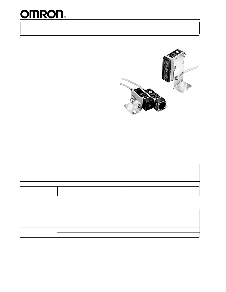
Prewired DC Sensor Provides Long-
Distance Sensing of Objects as Small
as 0.1 mm
s
Detect small objects over longer sensing
distances with highly accurate positioning
s
Attachable apertures allow detection down
to 0.1 mm diameter
s
Alarm output signals deteriorating detec-
tion conditions due to improper alignment
or dust contamination
s
Class I (FDA/IEC) laser product E3L-50,
requires no additional protective equip-
ment
s
Visible spot through-beam version aids in
critical alignment applications
Ordering Information
Method of detection
Through-beam
Diffuse reflective
Sensing distance
10 m (32.8 ft)
2 m (6.56 ft)
20 to 50 cm
(7.9 to 19.7 in)
Light source
Visible red
Infrared
Infrared
Laser class
Class II
Class I
Class I
Part number
NPN output
E3L-2RC4
E3L-2E4-50
E3L-DS50E4-50
PNP output
--
E3L-2B4-50
--
s
SENSORS
Laser Photoelectric Sensor
E3L
Description
Part number
Mounting bracket
For through-beam type; supplied with E3L-2 4- 50, E3L-2RC4
E39-L6
For diffuse reflective type; supplied with E3L-DS50E4-50
E39-L5
Sensitivity adjuster knob
E39-G1
Aperture with 0.85 mm dia. opening
E39-S56
Aperture with 0.10 mm dia. opening
E39-S55
s
REPLACEMENT PARTS
Apertures for
through-beam types
E3L
E3L
3
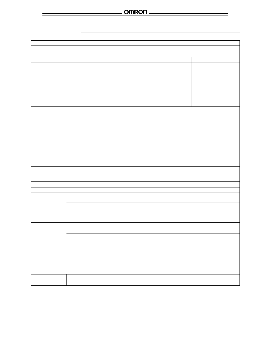
Specifications
Part number
E3L-2RC4 (See Note.)
E3L-2 4-50
E3L-DS50E4-50
Method of detection
Through-beam type
Diffuse reflective
Supply voltage
12 to 24 VDC,
�
10% max. ripple peak-to-peak
Current consumption
50 mA max.
40 mA max.
Sensing distance
10 m (32.8 ft) with no
2 m (6.56 ft) with 0.85 mm
20 to 50 cm (7.9 to 19.7 in)
aperture; 9 m (29.52 ft) with
dia. aperture; 20 cm (7.9 in)
with 2 x 2 mm (0.09 x 0.09 in)
3 mm aperture; 6 m (19.68 ft)
with 0.1 mm dia. aperture
white mat paper
with 2 mm aperture; 3 m
(9.84 ft) with 1 mm aperture;
2 m (6.56 ft) with 0.85 mm
aperture; 1 m (3.28 ft) with
0.5 mm aperture; 30 cm
(11.81 in) with 0.1 mm
aperture
Light source
Visible red, pulse modulated
Infrared, pulse modulated laser diode (
=780 nm) 25
�
W
laser diode (
=670 nm)
max., Class I FDA/IEC
480
�
W max.,
Class II FDA/IEC
Detectable object type
4 mm (0.16 in) dia. object
0.5 mm (0.02 in) dia. object
Opaque, translucent objects
minimum without aperture;
minimum with 0.85 mm dia.
2 x 2 mm
With aperture - object
aperture 0.1 mm (0.003 in)
minimum is same as
dia. object minimum with
aperture size
0.10 mm dia. aperture
Diameter of projected spot
With 4 mm dia. emitter, no aperture, at a distance of
With 4 mm dia. emitter, at a
2 m (6.56 ft), the incident light is 20 mm (0.79 in) in diameter
distance of 50 cm (19.7 in)
from the emitter, the incident
light is 2 mm (0.08 in) in dia.
Directional angle
Emitter: 2
�
max., Receiver: 20
�
max.
Operation mode
Light-ON/Dark-ON, wire selectable
Light-ON: + red, - black; Dark-ON: - red, + black
Sensitivity adjustment
Adjustable
Mutual interference protection
Standard level
Control
Type
NPN type, open collector
NPN type, constant current source (E3L-
E4-50)
output
PNP type, open collector (E3L-2B4-50)
Max. load
NPN type: 100 mA max.
NPN type: Load (relay, sink) logic: 80 mA max.
Voltage (source) logic: 1.5 to 3 mA
PNP type: Load (relay, source) logic: 80 mA max.
Response time
1 ms max. (both ON and OFF)
3 ms max. (both ON and OFF)
Type
NPN (E3L-
E4-50); PNP (E3L-2B4-50)
Max. load
50 mA, 24 VDC
Residual voltage
1 V
Response time
Output turns ON after 100 ms delay when light receiving signal level is within unstabe
zone.
Circuit
Output short-
Provided
protection
circuit
DC power supply
Provided
reverse polarity
Indicators
Light Incident (red LED), Stable Operation (green LED)
Materials
Lens
Plastic, PMMA
Case
Diecast zinc
DC
solid-
state
DC
solid-
state
Alarm
output
(This table continues on the next page)
Note: In consideration of vibration and other environmental and mounting conditions, the sensing distance values for the E3L-2RC4 are
very conservative. If these conditions can be minimized, longer sensing distances are possible. Please see excess gain and operating
range curves for more accurate sensing ranges.
E3L
E3L
4
Part number
E3L-2RC4
E3L-2 4-50
E3L-DS50E4-50
Mounting
Two side mount M4 threaded holes or
Two side mount M4 threaded
mounting bracket E39-L6 (supplied)
holes or mounting bracket
E39-L5 (supplied)
Connections
Prewired
2 m (6.56 ft); 3 conductor
2 m (6.56 ft); 3 conductor
2 m (6.56 ft) 4 conductor
cable for emitter, 3
cable for emitter, 4
cable
conductor cable for receiver
conductor cable for
receiver
Weight
Emitter: 160 g (5.6 oz)
250 g (8.8 oz)
Receiver: 175 g (6.2 oz)
Enclosure
UL
--
NEMA
NEMA 4
IEC 144
IP67
Ambient
Operating
-10
�
C to 50
�
C (14
�
F to 122
�
F) with no icing
Storage
-30
�
C to 70
�
C (-22
�
F to 158
�
F)
Specifications Table - continued from previous page
s
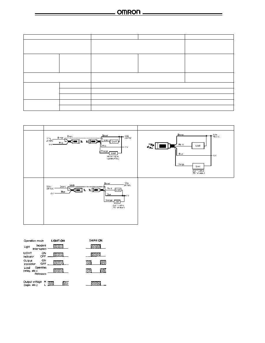
OUTPUT CIRCUIT DIAGRAMS
Sensor
Through-beam
Diffuse reflective
* Alarm (orange) wire not present for E3L-2RC4
*
The indicator can be wired for Light Incident by connecting the black
wires together as shown in the dotted line. For Power indication, connect
the emitter's black wire to the receiver's blue wire.
The indicator can be wired for Light Incident by connecting the black
wires together as shown in the dotted line. For Power indication, connect
the emitter's black wire to the receiver's brown wire.
NPN
output
type
PNP
output
type
s
TIMING CHARTS
(between brown
and black)
(between blue
and black)
(between blue
and black)
(between brown
and black)
E3L
E3L
5
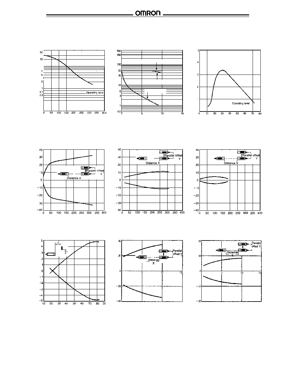
s
EXCESS GAIN
Through-beam Type E3L-2 4-50
Through-beam Type E3L-2RC4
Diffuse Reflective Type
E3L-DS50E4-50
Through-beam Type E3L-2 4-50
without aperture
Through-beam Type E3L-2 4-50
with 0.85 mm diameter aperture
Through-beam Type E3L-2 4-50
with 0.1 mm diameter aperture
s
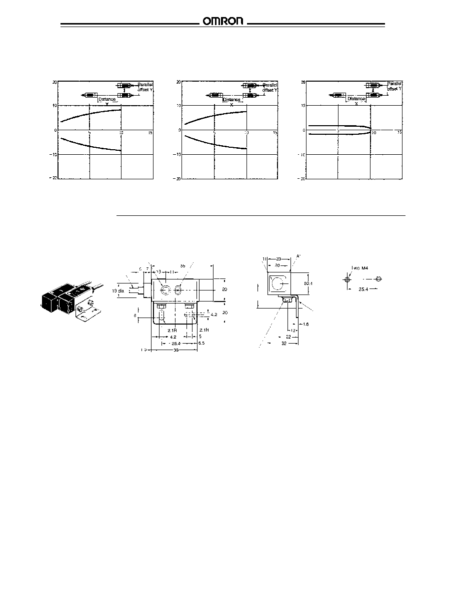
OPERATING RANGE
Diffuse Reflective Type
E3L-DS50E4-50
Through-beam Type E3L-2RC4
without aperture
Through-beam Type E3L-2RC4
with 1.0 mm diameter aperture
Excess gain ratio
Sensing distance (cm)
Excess gain ratio
Sensing distance (m)
Excess gain ratio
Sensing distance (cm)
Parallel of
fset distance
Y
(mm)
Sensing distance X (cm)
Parallel of
fset distance
Y
(mm)
Sensing distance X (cm)
Parallel of
fset distance
Y
(mm)
Sensing distance X (cm)
Parallel of
fset distance
Y
(mm)
Sensing distance X (cm)
with 2 x 2 mm
white mat paper
Parallel of
fset distance
Y
(mm)
Sensing distance X (m)
Parallel of
fset distance
Y
(mm)
Sensing distance X (m)
Slit 0.5, 1, 2, 3 mm dia.
Slit 0.85 mm dia.
Slit 0.1 mm dia.
E3L
E3L
6
Through-beam Type E3L-2RC4
with 0.85 mm diameter aperture
Through-beam Type E3L-2RC4
with 0.5 mm diameter aperture
Through-beam Type E3L-2RC4
with 0.1 mm diameter aperture
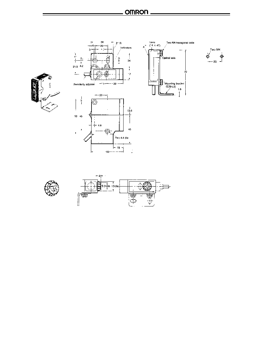
Dimensions
Unit: mm (inch)
s
THROUGH-BEAM TYPE E3L-2 4-
Mounting holes
Cable
2 m length
Sensitivity adjuster
Indicators
(for receiver only)
Lens
diameter
Mounting bracket
E39-L6 supplied
Two M4
hexagonal bolts
22.2
Note: Mounting bracket E39-L6
can be attached to surface "A".
Parallel of
fset distance
Y
(mm)
Sensing distance X (m)
Parallel of
fset distance
Y
(mm)
Sensing distance X (m)
Parallel of
fset distance
Y
(mm)
Sensing distance X (m)
E3L
E3L
7
Unit: mm (inch)
s
DIFFUSE REFLECTIVE TYPE E3L-DS50E4-50
Mounting holes
Cable, 2 m length
Note: Mounting bracket E39-L6
can be attached to surface "A".
s
REPLACEMENT PART
Sensitivity Adjuster Knob E39-G1 (included)
Note: The adjustment knob cannot
be removed once it has been
installed on the unit.
E3L
E3L
8
Operation
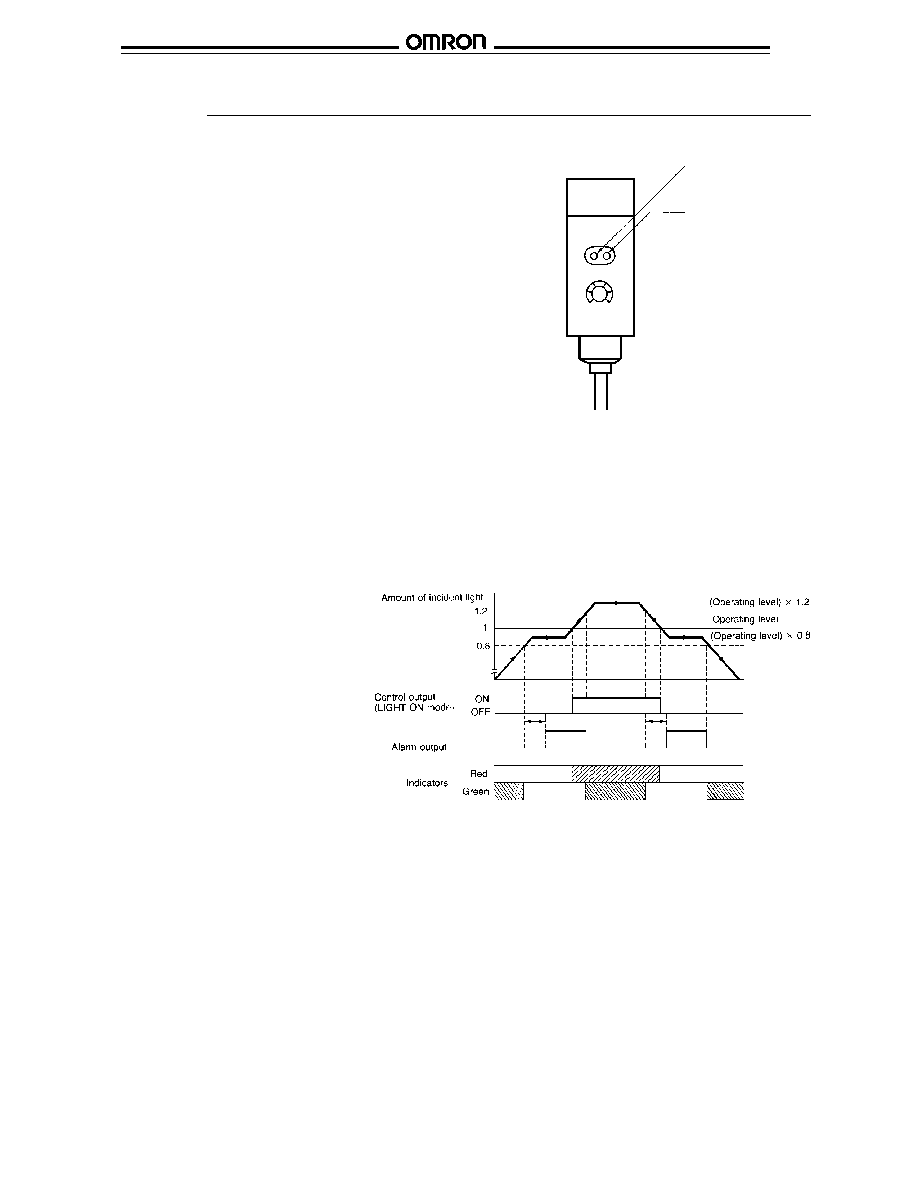
s
LIGHT INCIDENT INDICATOR
The LIGHT incident indicator (red LED) illuminates when the
light from the emitter is incident on the receiver and exceeds
the operating level (trigger point) of the sensor. This indicator
illuminates whenever the object is absent for through-beam
type and when the object is present for diffuse reflective type.
Stability indicator
(green LED)
Light incident indicator
(red LED)
s
STABILITY INDICATOR
The STABILITY indicator (green LED) illuminates when the
control output is in a stable OFF or ON state. A "stable" state
occurs when the receiver element of the sensor receives less
than 80% (OFF state) or more than 120% (ON state) of
incident light needed to operate the sensor.
The control output STABILITY indicator goes off every time the
amount of light incident on the receiver is within 20% of the
amount of light needed to change the control output state.
The unstable control output condition may occur when the
sensor encounters the leading and trailing edges of the object
to be detected. However, the alarm output described later will
not operate if the unstable condition recovers within 100 ms.
The condition can occur when a change in sensor position,
atmosphere (dust contamination), temperature or ambient light
causes the light incident on the receiving element to be near
the operating level of the sensor.
s
ALARM OUTPUT (-50 models)
The alarm output operates when the control
output is in an unstable OFF or ON state for
more than 100 ms. An unstable state occurs
when the amount of light incident upon the
receiver is within 20% of the amount of light
needed to change the control output state.
The alarm output feature indicates gradual
degradation of stability caused by changes in
sensor position, atmosphere, temperature or
ambient light that will eventually result in an
unstable control output. A change that occurs in
less than 100 ms will not cause the alarm
output to operate.
A 100 ms time delay is built into the alarm
output circuit. This prevents false triggering of
the alarm output as the leading and trailing
edges of the object to be detected are sensed.
When sensing objects moving at low speeds, a
separate ON-delay timer should be used to
prevent false triggering of the alarm output.

E3L
E3L
9
Precautions
s
STATIC ELECTRICITY
When handling the device, special care should be taken to avoid static electricity, as any static discharge can damage the laser diode
element of E3L photoelectric sensor.
s
LASER REGULATIONS
The E3L laser photoelectric sensor is intended for use as an
element incorporated into a larger system.
The E3L laser photoelectric sensor meets the standards
required by the Food and Drug Administration (FDA) in the
United States. OMRON has had also reported to the Center
for Devices and Radiological Health (CDRH). The report
includes the condition that the unit is to be used as a part of a
larger system.
Labels (FDA Regulations)
For products sold in North America, attach the following FDA
safety labels for the appropriate sensor body proir to use.
Some or all of these labels may already be attached.
Caution Label
E3l-2RC4
Certification and Identification Label
E3L-2L 4-50
E3L-DS50E4-50
E3L-2LRC4
TYPE E3L-2L
E4-50
(Tc=25*C, 25
�
W)
T: 50
�
sec ts: 2.5
�
sec f: 20 kHz
This product complies with 21 CFR 1040.10 and 1040.11
OMRON Corporation
10 TSUCHIDO-CHO, HANAZONO, UKYO-KU, KYOTO 615 JAPAN
MANUFACTURED JAN, 1990
TYPE E3L-DS50E4-50
(Tc=25*C, 25
�
W)
T: 200
�
sec ts: 5
�
sec f: 5 kHz
This product complies with 21 CFR 1040.10 and 1040.11
OMRON Corporation
10 TSUCHIDO-CHO, HANAZONO, UKYO-KU, KYOTO 615 JAPAN
MANUFACTURED JAN, 1990
TYPE E3L-2LRC4
(Tc=25*C, 40
�
W)
T: 60
�
sec ts: 5
�
sec f: 16.7 kHz
This product complies with 21 CFR 1040.10 and 1040.11
OMRON Corporation
KARASUMA NANAJO, SHIMOGYO-KU, KYOTO 600 JAPAN
MANUFACTURED , 1990
Aperture Label for E3L-2LRC4
AVOID
EXPOSURE
LASER
RADIATION IS
EMITTED FROM
THIS APERTURE
Labels (European)
For exports to European countries, attach the appropriate
label shown below to the cable.
E3L-2 4-50 & E3L-DS50E4-50
E3L-2RC4
CLASS I
LASER PRODUCT
LASER RADIATION
DO NOT STARE INTO BEAM
CLASS 2 LASER PRODUCT
Weight:
670 nm
Maximum output:
2 mw (Peak)
Pulse duration:
5 sec
s
MAINTENANCE
The E3L laser photoelectric sensor contains no user-
serviceable parts. Refer all servicing to an authorized
OMRON agent.
These devices generate Class I or Class II laser radiation.
Avoid looking at the beam for prolonged periods.
Note: For more information on laser safelt and requirements,
please see Omron's Measurement Sensors Catalog.
Do not disassemble the unit. Users expose themselves to
the risk of laser radiation if they disassemsble the device,
or use it for any purpose other than those described in this
data sheet or in the instruction sheet provided with the unit.
Caution

E3L
E3L
OMRON ELECTRONICS LLC
OMRON CANADA, INC.
One East Commerce Drive
885 Milner Avenue
Schaumburg, IL 60173
Scarborough, Ontario M1B 5V8
1-800-55-OMRON
416-286-6465
Cat. No. CEDSAX4
11/01
Specifications subject to change without notice.
Printed in the U.S.A.
OMRON ON-LINE
Global - http://www.omron.com
USA - http://www.omron.com/oei
Canada - http://www.omron.com/oci