 | –≠–ª–µ–∫—Ç—Ä–æ–Ω–Ω—ã–π –∫–æ–º–ø–æ–Ω–µ–Ω—Ç: E3MC-A41 | –°–∫–∞—á–∞—Ç—å:  PDF PDF  ZIP ZIP |
Document Outline
- Front Page
- Ordering Information
- Specifications
- Application Examples
- Engineering Data
- Nomenclature
- Operation
- Dimensions
- Installation
- Terms
- Reference Information
- Precautions
- Contacting Omron
- HOME
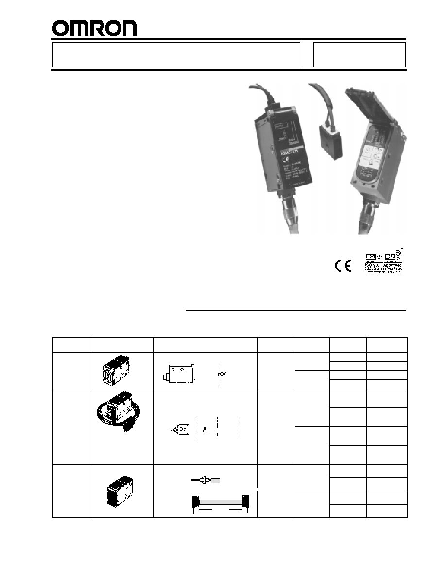
RGB Color Sensor
E3MC
RGB Color Sensor Detects Subtle
Color Differences--Most Advanced
Color Sensor In the Industry
LED light source insures ease of
operation and long life
No separate light source is required
Remote control of color setting from PC
or PLC
4-color memory
4-output models available
3 models: lensed, precision fiber-optic,
versatile standard fiber-optic
IP66
Rugged die-cast metal housing
Ordering Information
RGB COLOR SENSOR
Type
Appearance
Sensing distance
Spot
diameter
No. of
outputs
Output
Part number
Lensed
0
50
100
12 mm
1
NPN
E3MC-A11
PNP
E3MC-A41
60
±
10 mm
4
NPN
E3MC-MA11
(See Note.)
PNP
E3MC-MA41
Precision
fiber-optic
type
3 mm
1
NPN
E3MC-X11
type
0
50
100
PNP
E3MC-X41
The shape of the
amplifier section is
(See Note.)
20
±
4 mm
4
NPN
E3MC-MX11
amplifier section is
the same as for the
E3MC-(M)A
.
PNP
E3MC-MX41
General-
purpose
Standard sensing distance
Varies with
the recom-
1
NPN
E3MC-Y11
ur ose
fiber-optic
type
E32-CC200
(See Note 2.)
5 mm
the recom-
mended
fiber.
PNP
E3MC-Y41
ty e
E32 T16
(See Note 2.) fiber.
4
NPN
E3MC-MY11
E32-T16
200 mm
PNP
E3MC-MY41
Note:
Refer to the
Specifications section of this data sheet.
E3MC
E3MC
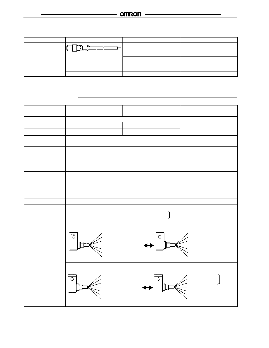
ACCESSORIES (ORDER SEPARATELY)
Item
Appearance
Description
Part number (length)
Sensor cable (2-m
cable is included with
the E3MC)
Replacement cable
E39-C1 (2M)
5-meter cable
E39-C1 (5M)
Mounting bracket
------
Used for die-cast body mounting
(See Note.)
E39-L114
------
Used for DIN-rail mounting
E39-L115
Note: Included with sensor.
Specifications
Type
Lensed
Precision fiber-optic type
General-purpose fiber-optic type
y
E3MC-A
1, E3MC-MA
1
E3MC-X
1, E3MC-MX
1
E3MC-Y
1, E3MC-MY
1
Light source
Red (680 nm), green (525 nm), and blue (450 nm) LEDs
Sensing distance
60
±
10 mm
20
±
4 mm
Varies with the recommended
fiber Refer to Engineering Data
Spot diameter
12 dia.
3 dia.
fiber. Refer to Engineering Data
for details.
Supply voltage
12 to 24 VDC
±
10%, ripple (p-p) 10% max.
Current consumption
100 mA max.
Output
Load current: 100 mA max.
NPN open collector output with a maximum residual voltage of 1.2 V for the E3MC-(M)A11, E3MC-(M)X11,
and E3MC-(M)Y11.
PNP open collector output with a maximum residual voltage of 2.0 V for the E3MC-(M)A41, E3MC-(M)X41,
and E3MC-(M)Y41.
L.O./D.O., switch selectable
Response time
1-output model:
Standard mode: 3 ms max.
High-speed mode: 1 ms max. (switch selectable)
4-output model:
Standard mode: 6 ms max.
High-speed mode: 2 ms max. (switch selectable)
Timer function
40-ms OFF-delay timer (ON/OFF switch selectable)
Color detection
Four colors stored in teaching operation with manual threshold level adjustments.
Color detection mode
Mode C: RGB ratio detection; adapts to changes in conditions
Mode I: RGB light intensity detection; highest precision
Switch selectable
Mode selection
E3MC-
11/-
41
Mode A (Factory-set)
Mode B (for remote teaching)
Output (white)
Not used (gray)
Bank selection input 1 (yellow)
Bank selection input 2 (green)
External synchronous input (pink)
V
CC
(brown)
0 V (blue)
Colors in parentheses are lead wire colors.
Output (white)
Answer-back output (gray)
Remote control input (yellow)
Not used (green)
External synchronous input (pink)
V
CC
(brown)
0 V (blue)
Colors in parentheses are lead wire colors.
E3MC-M
11/-
M41
Mode A (Factory-set)
Mode B (for remote teaching)
Output 1 (white)
Output 2 (gray)
Output 3 (yellow)
Output 4 (green)
External synchronous input (pink)
V
CC
(brown)
0 V (blue)
Colors in parentheses are lead wire colors.
Output 1 (white)
Output 2 (gray)
Output 3 (yellow)
V
CC
(brown)
0 V (blue)
Colors in parentheses are lead wire colors.
Answer-back output (green)
Remote control input (pink)
3 outputs
(This table continues on the next page.)
E3MC
E3MC
Specifications Table
-- continued from previous page
Type
Lensed
Precision fiber-optic type
General-purpose fiber-optic type
y
E3MC-A
1, E3MC-MA
1
E3MC-X
1, E3MC-MX
1
E3MC-Y
1, E3MC-MY
1
Remote control input
(See Note 1.)
(mode B only)
The following control is performed according to the control signal input.
E3MC-
11/-
41
Bank selection, remote teaching, or threshold selection
E3MC-M
11/-M
41
Channel selection, remote teaching, or threshold selection
Answer-back output
(mode B only)
Load current: 100 mA max.
NPN open collector output with a residual voltage of 1.2 V max.
E3MC-(M)A11/-(M)X11/-(M)Y11
PNP open collector output with a residual voltage of 2.0 V max.
E3MC-(M)A41/-(M)X41/-(M)Y41
External synchronous
input
Response time: 1 ms max. (The 4-output model is not available in mode B.)
Color detection
4 banks selectable (either by bank selection input or by using the SELECT button)
Input response time for bank selection: 50 ms max.
Indicator
Operation indicator (orange LED), 4-level bank indicator (green LED, See Note 3.), 7-level threshold
indicator (red LED), 8-level detection indicator (green LED), and four channel indicators (orange LED, See
Note 4.)
Protection
Protection from reversed power supply connection and output short-circuit
Ambient light immunity
Incandescent lamp: Illumination on optical spot: 3,000
x max.
Sunlight: Illumination on optical spot: 10,000
x max.
Ambient temperature
Operating: --25
∞
C to 55
∞
C (--13
∞
F to 131
∞
F) with no icing
Relative humidity
Operating: 35% to 85% (with no condensation)
Permissible fiber
bending radius
---
10 mm min.
Varies with the type of selected
fiber (see specific fiber
specifications)
Insulation resistance
20 M
min. (at 500 VDC)
Dielectric strength
1,000 VAC, 50/60 Hz for 1 min
Vibration resistance
10 to 55 Hz, 1.0-mm double amplitude or 150 m/s
2
(approx. 15G) for 2 hrs each in X, Y, and Z axis.
0.75-mm double amplitude or 100 m/s
2
(10G) when using a Mounting Bracket.
Shock resistance
500 m/s
2
(approx. 50G) for 3 times each in X, Y, and Z axis.
300 m/s
2
(30G) when using a Mounting Bracket.
Enclosure rating
IEC IP66 (with protective cover in place)
Material
Case: Zinc die-cast
Cover: PES
Case: Zinc die-cast
Cover: PES
Fiber head: ABS
Case: Zinc die-cast
Cover: PES
Weight (with 2-m cable)
Approx. 350 g
Approx. 400 g
Approx. 350 g
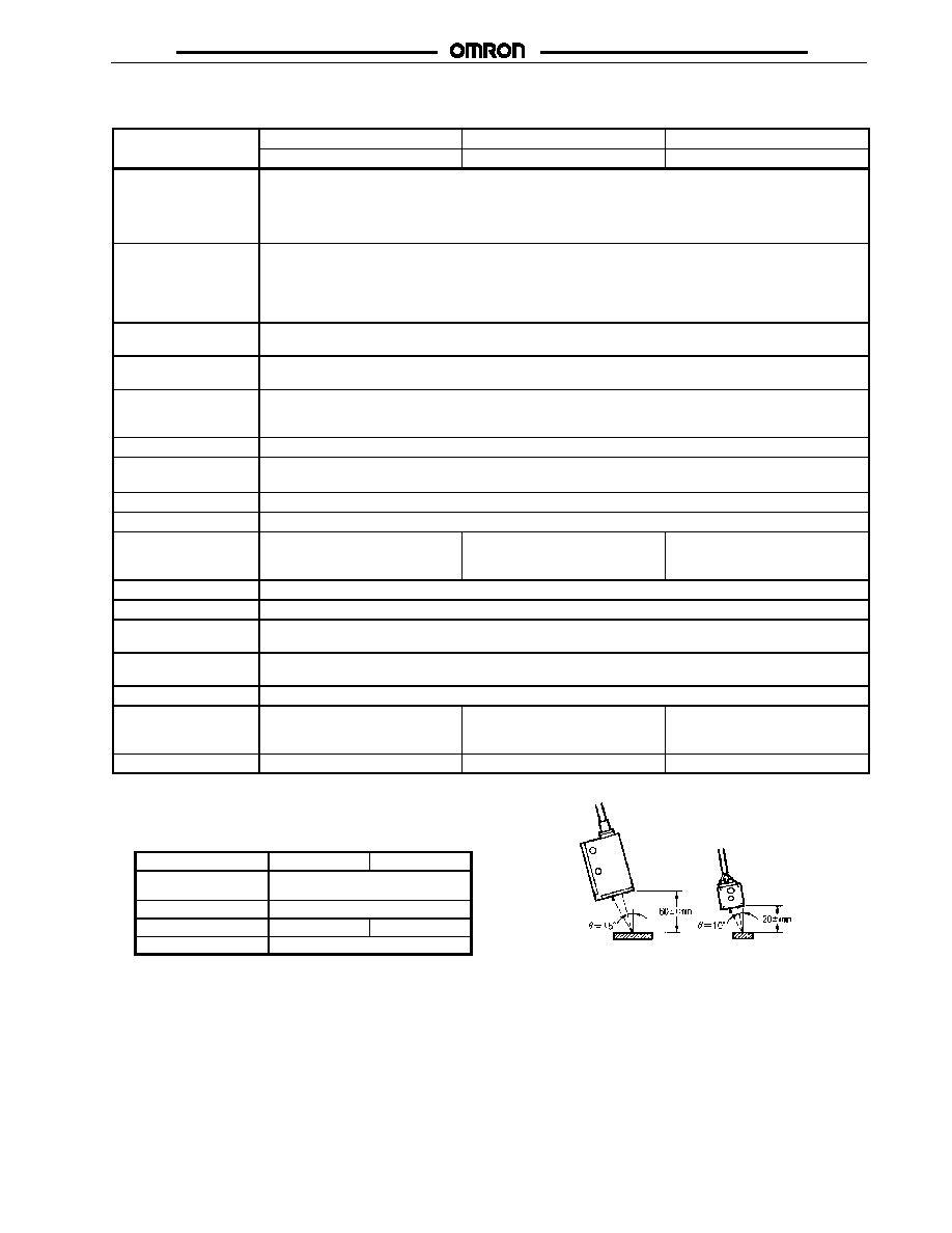
Note: 1. Refer to
Remote Teaching.
2. Definition of Sensing Distance
Refer to the following table and the diagram to the
right.
Item
E3MC-(M)A
E3MC-(M)X
Color discrimination
mode
Mode C
Response time
Standard mode
Tolerance (
)
15
∞
10
∞
Detectable colors
11 standard colors
E3MC-(M)X
Fiber Head
Sensing target
E3MC-(M)A
Sensing target
3. 1-output models only: E3MC-A
/-X
/-Y
4. 4-output models only: E3MC-MA
/-MX
/-MY
E3MC
E3MC
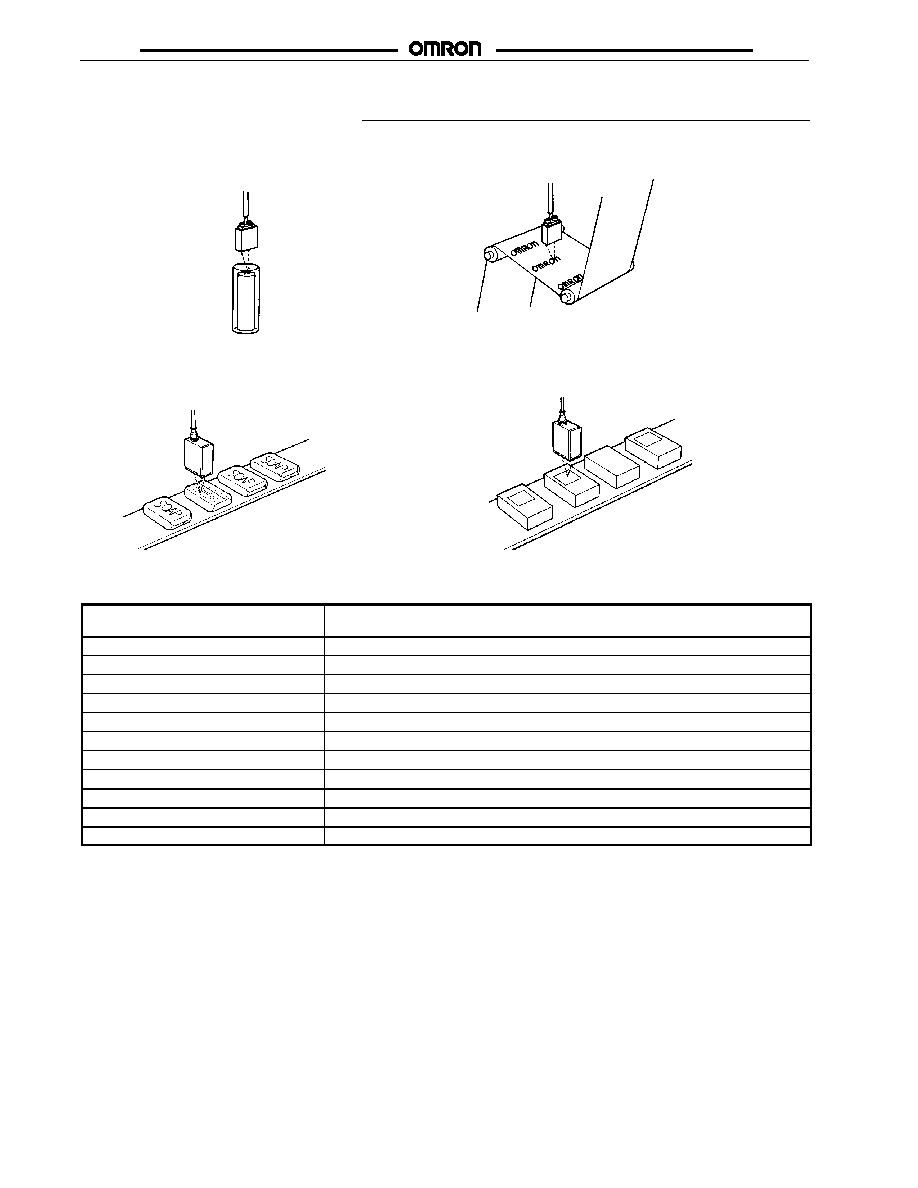
Application Examples
DETECTING INTERNAL YELLOW
RESIN PLATES OF A BATTERY
PATTERN POSITIONING
DETECTING LABELS
DISCRIMINATING FRONT AND BACK
SIDES OF OBJECTS
STANDARD SENSING OBJECTS
Color
(11 standard colors)
Munsell color notation (See Note.)
White
N9.5
Red
4R
4.5/12.0
Yellow/red
4YR
6.0/11.5
Yellow
5Y
8.5/11.0
Yellow/green
3GY
6.5/10.0
Green
3G
6.5/9.0
Blue/green
5BG
4.5/10.0
Blue
3PB
5.0/10.0
Blue/purple
9PB
5.0/10.0
Purple
7P
5.0/10.0
Red/purple
6RP
4.5/12.5
Note: Munsell Color Notation: A color classification system that assigns three values to each color: Hue, Value, and Chroma. System
was developed by Albert Munsell and published in 1905.
E3MC
E3MC
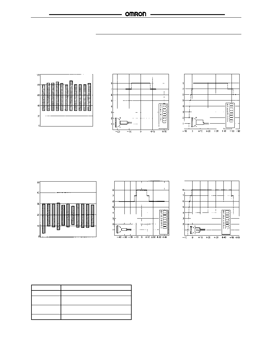
Engineering Data
SENSING DISTANCE VS.
COLOR DIFFERENCES
(TYPICAL)
ANGLE
CHARACTERISTICS
(TYPICAL)
ANGLE
CHARACTERISTICS
(WHEN TEACHING AT
AN INCLINATION OF 15
)
S
ens
i
n
g
d
i
s
tanc
e
(mm)
De
te
ctio
n
l
e
v
e
l
Angle (
∞
)
Angle (
∞
)
Detection
level
Detection
level
De
te
ctio
n
l
e
v
e
l
Wh
it
e
Re
d
Y
e
llo
w/r
e
d
Y
e
llo
w
Y
e
llo
w/g
r
e
e
n
Green
B
l
ue/green
Blu
e
B
l
ue/purpl
e
Pu
r
p
le
R
ed/purpl
e
Sensing target:
Blue/Green
30 x 27 mm
Sensing target:
Blue/Green
30 x 27 mm
E3MC-(M)A
(X Direction)
E3MC-(M)A
E3MC-(M)A
(Y Direction)
SENSING DISTANCE VS.
COLOR DIFFERENCES
(TYPICAL)
ANGLE
CHARACTERISTICS
(TYPICAL)
ANGLE
CHARACTERISTICS
(WHEN TEACHING AT
AN INCLINATION OF 10
)
S
ens
i
n
g
d
i
s
tanc
e
(mm)
Angle (
∞
)
Angle (
∞
)
Detection
level
Detection
level
De
te
ctio
n
l
e
v
e
l
De
te
ctio
n
l
e
v
e
l
Wh
it
e
Re
d
Y
e
llo
w/r
e
d
Y
e
llo
w
Y
e
llo
w/g
r
e
e
n
Green
B
l
ue/green
Blu
e
B
l
ue/purpl
e
Pu
r
p
le
R
ed/purpl
e
Sensing target:
Blue/Green
30 x 27 mm
Sensing target
Blue/Green
30 x 27 mm
E3MC-(M)X
E3MC-(M)X
(X Direction)
E3MC-(M)X
(Y Direction)
GENERAL-PURPOSE FIBER-OPTIC TYPE
Recommended Fiber: Diffuse Fiber-Optic
The following optical fibers are recommended for use with the
E3MC-(M)Y
.
Part number
Sensing distance (See Note 1.)
E32-DC200
5 mm
E32-CC200
(See Note 2.)
5 mm
E32-D32L
(See Note 3.)
4.5 mm
E32-D11L
5 mm
Note: 1. The E3MC-(M)Y
discriminates eleven colors at the
above distances. For a typical example, nine colors are
discriminated at a sensing distance of 12 mm.
2. The fiber to be inserted into the emitter is indicated
with white lines. Insert the amplifier fiber into the lower
emitter section.
3. The fiber to be inserted into the emitter is indicated
with dotted yellow lines. Insert the amplifier fiber into
the lower emitter section.
E3MC
E3MC
Sensing Distance of a Diffuse Fiber
Sensing distance
Sensing target
E32-DC200, etc.
RECOMMENDED FIBER: THROUGH-
BEAM FIBER
The following optical fibers are recommended for use with the
E3MC-(M)Y
.
Part number
Sensing range (See Note.)
E32-TC200
30 mm
E32-T11L
60 mm
E32-T16
200 mm
E32-T17L
1.1 m
Note: The E3MC-(M)Y
discriminates red, blue, and yellow
films at the above distances.
AVAILABLE OPTICAL FIBERS
In addition to the previous recommended optical fibers, the following optical fibers are available for the E3MC-(M)Y
. Refer to the
E3X-NH Datasheet (E258-E1) for the following optical fibers in detail. Optical fibers other than the following are not available.
Part number
Sensing method
Remarks
E32-TC200A
Through-beam
Not different from
th E32 TC200 i
E32-TC200B
g
the E32-TC200 in
optical
E32-TC200C
optical
characteristics.
E32-TC200D
characteristics.
E32-T12L
Not different from
the E32-T11L in
optical
characteristics.
E32-T14
---
E32-T11
E32-T11R
Through-beam
(R1 fiber)
---
Part number
Sensing method
Remarks
E32-DC200B
Diffuse
Not different from
th E32 DC200 i
E32-DC200C
the E32-DC200 in
optical
E32-DC200D
optical
characteristics.
E32-D12
characteristics.
E32-D11
E32-D11R
Through-beam
(R1 fiber)
---
E32-G14
Groove
---
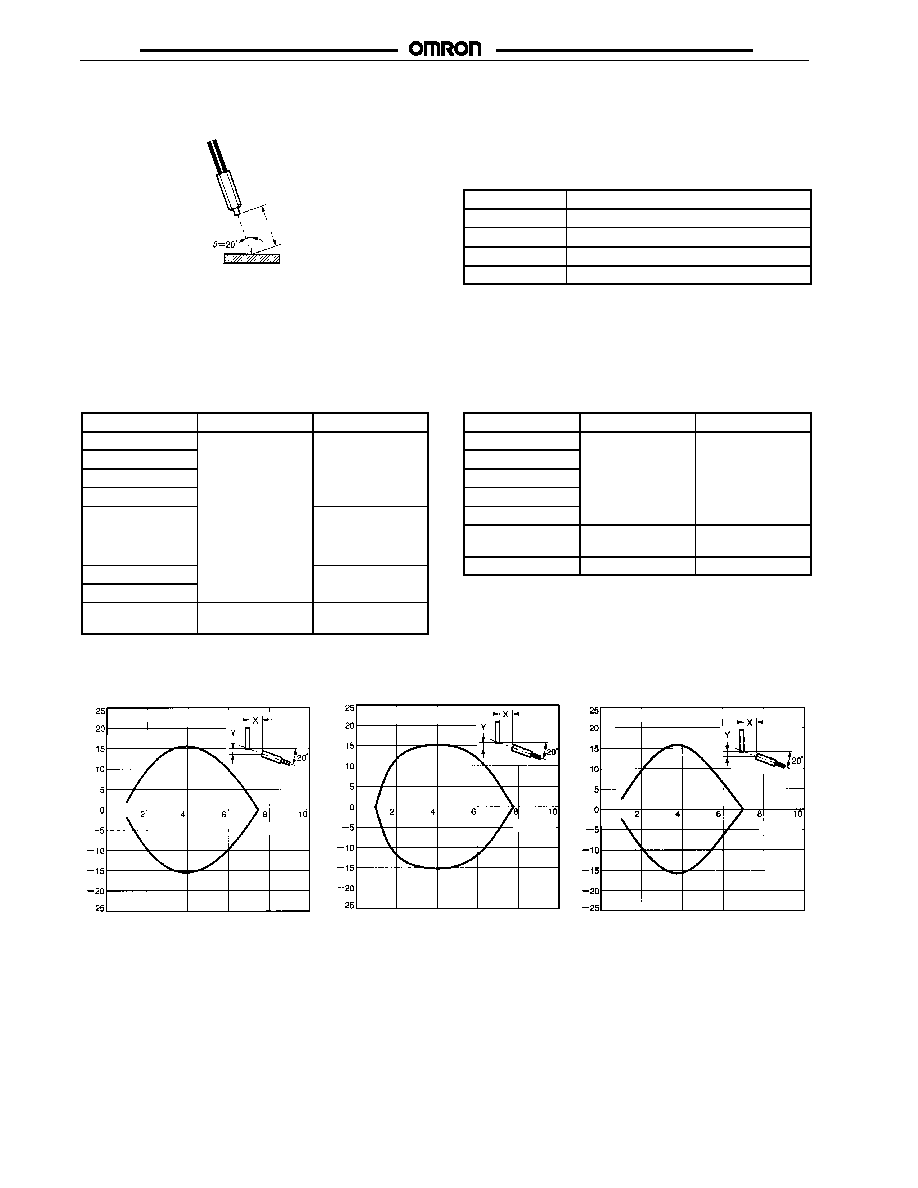
OPERATING RANGE CHARACTERISTICS (TYPICAL)
E32-DC200
E32-CC200
E32-D32L
Di
s
t
anc
e
Y
(m
m
)
Di
s
t
anc
e
Y
(m
m
)
Di
s
t
anc
e
Y
(m
m
)
Sensing target: Blue/Green 38 x 38 mm
Sensing target: Blue/Green
38 x 38 mm
Sensing target: Blue/Green 38 x 38 mm
Distance X (mm)
Distance X (mm)
Distance X (mm)

E3MC
E3MC
E32-D11L
Sensing Target:
Red, Blue, and Yellow Films
Di
s
t
anc
e
Y
(m
m
)
Sensing target: Blue/Green 38 x 38 mm
Sensing target: Film in Red (rosco/UX, scarlet)
Sensing target: Film in Blue (rosco/UX, skyblue)
Sensing target: Film in Yellow (rosco/UX, straw)
The above color films are made by the rosco company.
Distance X (mm)
Distance X (mm)
E32
-TC200
E32
-T11L
E32
-T16
E32
-T17L
Sensing Target: Bottle
E32-T17L
CHROMATIC SENSITIVITY (TYPICAL)
Sensing target: 63-dia green bottle
Sensing target: 60-dia brown bottle
Sensing target: 63-dia dark-brown
bottle
Green
bottle
Brown
bottle
Dark-
brown
bottle
Distance X (mm)

E3MC
E3MC
Nomenclature
Operation Indicator (Orange)
Illuminated when output is ON.
Under mode B (single-output
models), the indicator will be
illuminated when mode B is
active or when the mode selec-
tor is set to TEACH.
Bank Indicator (Green)
1-channel models. Displays
selected bank.
TEACH Button
Stores target color. On 4-channel
models, used to check the number
of channels that are indicated by
both the operation indicator and
channel indicator.
Detection Level Indicator (Green)
Displays similarity level between
registered and detectable colors.
Threshold Indicator (Red)
Displays threshold level.
SELECT UP Button, SELECT DOWN Button
Bank selection
Threshold adjustment
Mode Selector
Selects TEACH, ADJ, or RUN mode.
Function Switch (see details below)
Color discrimination mode selection
Response time selection
OFF-delay timer setting
Conformity/Non-conformity output selection
(See glossary--Light/Dark Operate)
E3MC ALL MODELS
Tolerance #1
Tolerance #7
Channel Indicator (Orange)
4-channel models. Displays
selected channels. Illuminated
when the output of each channel
is ON.
Color Discrimination Mode Selection (Mode C is Recommended for Normal Applications)
Mode C: Color discrimination is performed according to R (red), G (green), and B (blue) ratio of the reflection light even
if the sensing objects fluctuate up and down within the rated sensing range.
Mode I: Color discrimination is performed according to RGB light intensity of reflection light. This mode ensures more
delicate color discrimination than mode C.
Response Time Selection
3 ms (6 ms): The E3MC can stably detect minute differences of color. Set the response time to 3 ms for usual
applications.
1 ms (2 ms): The E3MC will be in quick-response operation. Set the response time to 1 ms if high-speed response is
required.
OFF-delay Timer Setting
---:
No OFF-delay timer is set.
TMR: A 40-ms OFF-delay timer is set for control output.
Conformity/Non-conformity Output (See glossary--Light/Dark Operate)
=:
Output is ON when the detected color coincides with the registered color.
:
Output is ON when the detected color does not coincide with the registered color.
1 ms
(2 ms)
(6 ms)
3 ms
Note: Figures shown in parentheses are for the 4-output models.
Function Switch
The following settings are possible in RUN or ADJ mode. (Each pin of the function switch is factory-set to the upper position.)
C
TMR

E3MC
E3MC
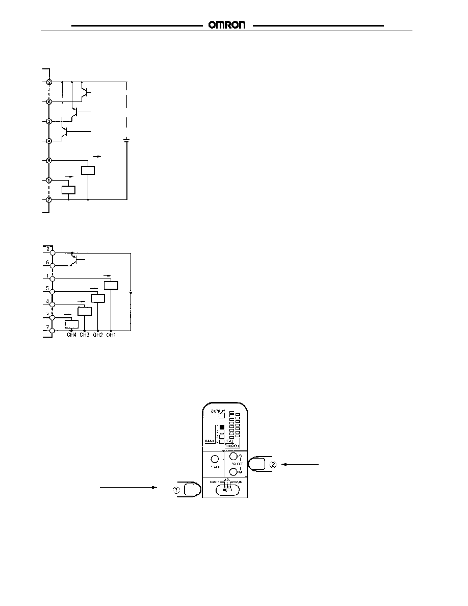
Operation
OUTPUT CIRCUITS
Connector Pin Arrangement For All Models
Note: Pin 8 is not used.
E3MC-
11 with NPN Output (1-output Models)
Brown
White
Yellow
Green
Pink
Blue
Load
Control output
Not used/Answer-back
output
Bank selection input 1/
Remote control input
Bank selection input 2/
Not used
12 to 24 VDC
Gray
Load
External synchronous
input
E3MC-M
11 with NPN Output (4-output Models)
12 to 24 VDC
Control
output
Load
External
synchronous input
Brown
White
Yellow
Load
Load
Load
Control
output
Control
output
Control
output
Gray
Green
Pink
Blue
E3MC
E3MC
E3MC-
41 with PNP Output (1-output Models)
Load
Brown
Green
Pink
White
Blue
Control
output
12 to 24 VDC
Yellow
Gray
Load
Note used/Answer
back output
Bank selection input 1/
Remote control input
Bank selection input
2/Not used
External synchronous input
12 to 24 VDC
Load
Load
Load
Load
Control
output
Control
output
Control
output
Control
output
Brown
White
Yellow
Gray
Green
Pink
Blue
External
synchronous input
E3MC-M
41 with PNP Output (4-output Models)
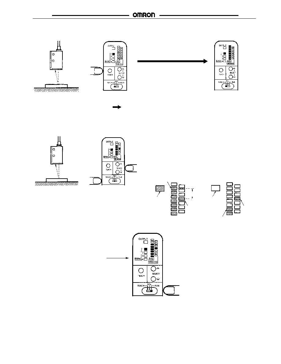
SETTINGS
E3MC-A
/E3MC-X
-- -- Single-Output Models
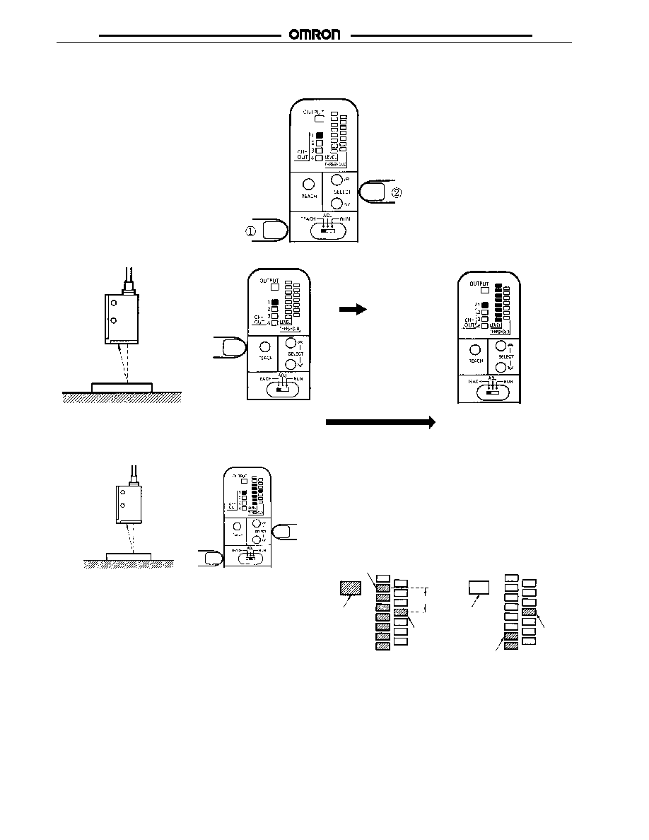
1.
Bank Selection
Set the Mode Selector to the TEACH mode, and then select the BANK using the SELECT button.
Then press SELECT buttons,
scrolling through banks 1 -- 4.
To select banks 1 -- 4, first slide 3-position
switch to "TEACH."
E3MC
E3MC
2.
Color Registration
Position the registered object at the
detection point and press the TEACH
button.
All the red threshold indicators
will flash if the E3MC receives
excessive light.
All the detection level
indicators are illuminated.
Registered object
OK
No Good
Sensor
3.
Threshold Adjustment (If Required)
Sensor
Sensing target
Press the SELECT button in ADJ mode with or without
the object to be detected positioned at the detection
point.
Detection Level and Tolerance
As the detected color becomes closer to the registered
color, the number of illuminated detection level indicators
increases. When the E3MC is in conforming output mode,
the control output of the E3MC will be ON if the detection
level exceeds the threshold level and OFF if the detection
level does not exceed the threshold level.
Set the threshold to a higher level for highly-precise color
discrimination and to a lower level to ignore minor tint
differences or dirt retention.
Detection level
Operation indicator
illuminated:
Control output ON
Tolerance
Threshold
value
Detection level
Threshold
value
Operation indicator
not illuminated:
Control output OFF
4.
Operation
Detection operation is performed in RUN mode.
ON/OFF status of each bank is displayed on the
bank indicators.
Bank Indicators
E3MC
E3MC
E3MC-MA
/E3MC-MX
-- -- 4-Output Models
1.
Channel Selection
Set the Mode Selector to the TEACH mode.
Then select the channel using the SELECT button.
2.
Color Registration
Position the registered object at the detection point
and press the TEACH button.
All the red threshold
indicators will flash if
registration has not been
completed.
All the detection level
indicators are illuminated.
Registered object
OK
No Good
Sensor
3.
Threshold Adjustment (If Required)
Sensor
Sensing object
Press the SELECT button in ADJ mode with or without the object
to be detected positioned at the detection point. The channel
selected in the TEACH mode or RUN mode will become the
channel for the ADJ mode.
Detection Level and Tolerance
As the detected color becomes closer to the registered color, the
number of illuminated detection level indicators increases. When
the E3MC is in conforming output mode, the control output will be
ON if the detection level exceeds the threshold level and OFF if
the detection level does not exceed the threshold level.
Set the threshold to a higher level for highly-precise color
discrimination and to a lower level to ignore minor tint differences
or dirt accumulation.
Detection level
Operation
indicator:
illuminated
Control output:
ON
Tolerance
Threshold
value
Detection level
Threshold
value
Operation
indicator: Not
illuminated
Control output:
OFF

E3MC
E3MC
4.
Operation
For indicating detection level and threshold value for other channels
Press the SELECT button.
For checking which channel
is indicated with the operation
indicator.
Press the
TEACH button.
Displays the channel whose detection
level is currently indicated in the
channel indicator for three seconds.
Displays the selected channel for
three seconds and indicates
detection level and threshold value
of the selected channel.
The detection operation is performed in RUN
mode. ON/OFF status of each channel is
displayed on the channel indicators. Doubly
displayed channels (operation indicator and
channel indicator) can be checked and
selected by pressing the TEACH button and
selected by pressing the SELECT button.
DETECTION LEVEL AND INDICATOR
Indicator
Detection
level
1
2
3
4
5
6
7
8
TECHNICAL GUIDE
If the E3MC does not detect metal or glossy objects accurately, change the mounting angle of the E3MC so that it will not receive regular
reflection light directly reflected from the objects.
The mounting angle of the E3MC-X
can be adjusted to approximately 10
∞
with the mounting holes.
Object to be detected
Object to be detected
E3MC-X
E3MC-A
Note: To avoid malfunction, provide a cover to shut out direct
external light interference to the E3MC.
Sensing target
E3MC-(M)Y
(reflective optical fiber)
0 to 20
∞
On the other hand, sensing targets such as metal or transparent
plastic cases may be detected by allowing regular reflection.
Detection of White, Gray, or Black Objects
When registering white, gray, or black objects, change the color
discrimination mode to "Mode I" to achieve a more stable color
discrimination.
External Light
The E3MC may malfunction if it directly receives external light
interference. Provide a cover to shut-out such external light
interference.

E3MC
E3MC
Adjustment of Sensing Distance of General-purpose
Fiber-optic Type
Unlike the E3MC-A or E3MC-X, the E3MC-Y may require
adjustment of its sensing distance depending on the reflection
rate. This also applies to the through-beam type.
Bring the fiber head as
close as possible to the workpiece
and conduct teaching.
Feed workpieces and
check if they are detected.
Excessive light. Move the
head away from the work-
piece and find a position
where teaching is accepted.
This position is the optimum
distance.
OK: All Detection Level
Indicators (green) illuminated.
NG: All Threshold
Indicators (red)
flashing.
REGISTERED COLOR SELECTION (BANK SELECTION INPUT)
Single-Output Models ONLY (E3MC-A
/E3MC-X
/E3MC-Y
)
The E3MC in RUN mode offers bank selection with external inputs by combining bank selection input 1 (yellow) and input 2 (green). The
selected bank is active when the indicator is illuminated.
NPN (E3MC-A11/-X11/-Y11)
Bank
Input 1
Input 2
1
OPEN
OPEN
2
GND
OPEN
3
OPEN
GND
4
GND
GND
PNP (E3MC-A41/-X41/-Y41)
Bank
Input 1
Input 2
1
OPEN
OPEN
2
Vcc
OPEN
3
OPEN
Vcc
4
Vcc
Vcc
EXTERNAL SYNCHRONOUS INPUT FUNCTION (See Note.)
The measurement results will be directly output to the control output if the input from the external synchronous input terminal (pink) is set
to OFF. The output will hold the previous status if the input of the external synchronous input terminal is set to ON. External synchronous
input is valid in RUN or ADJ mode.
Condition
NPN (E3MC-
11)
PNP (E3MC-
41)
ON (Status on hold)
GND
Vcc
OFF (Result output)
OPEN
OPEN
External synchronous input
Control output
Sensing target
Discrimination result
Same color
Different color
Same color
Same color
Output on hold
Output on hold
This status can be on
hold by an external
synchronous input. It
will be released by
setting the external
synchronous input to
OFF.
This status can be on
hold so that unwanted
color objects can be
ignored while they are
passing the sensing
range.
Note: External Synchronous Input: Latches sensor output in existing state when ESI is on. For example, if sensor output is on when ESI
is on, the output(s) will remain on until ESI is turned off, regardless of target presence or absence.
For NPN models, ESI is turned on by connections to 0V.
For PNP models, ESI is turned on by connections to +V.
E3MC
E3MC
REMOTE TEACHING (REMOTE CONTROL FUNCTION)
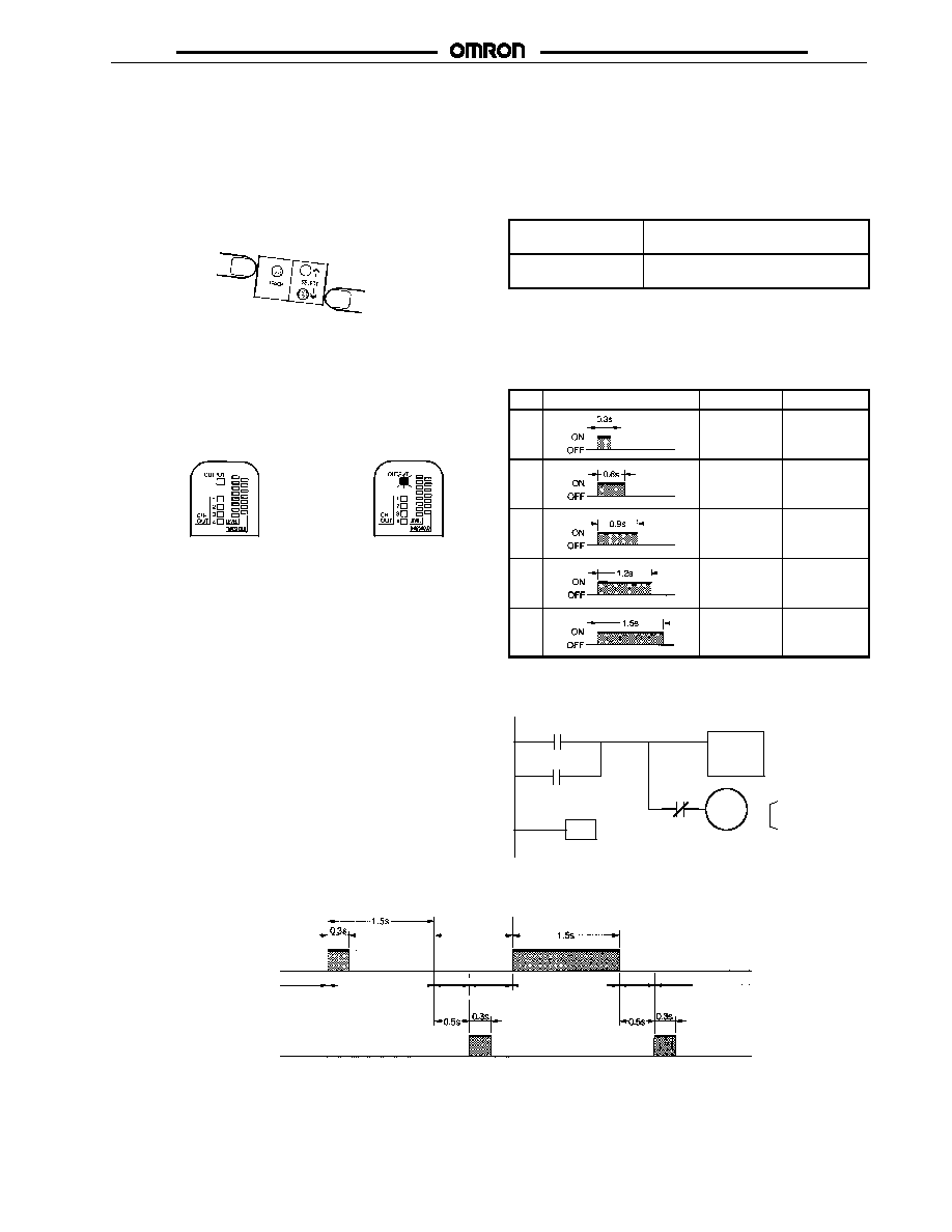
Mode Setting
When using the remote control function of the Sensor for remote
teaching, be sure to set the Sensor to mode B.
Setting Method
Apply power to the Sensor while pressing the SELECT DOWN
button and TEACH button together.
Checking Method
Mode A or B of the E3MC will be displayed for 3 s after mode
setting. When the mode selector is set to TEACH, the mode can
be checked from the operation indicator. The indicator will be lit
when the mode is set to B.
Mode A:
Operation indicator
is OFF.
Mode B:
Operation indicator
is ON.
Note: 1. The Sensor is set to mode A before shipping.
2. The current mode selected does not change after the
Sensor is turned OFF.
3. The remote control function is available in RUN mode
and ADJ mode only.
4. The E3MC-M
has three outputs in mode B and no
external synchronous input will be accepted.
5. The same switching procedure can be used for chang-
ing to mode A.
Remote Teaching Method
Function 1: Remote teaching with manual input through an
external connection
Short-circuit the remote control input for 1.5 s or more to either of
the following terminals according to the E3MC model.
NPN type
(E3MC-
11)
Short-circuit to GND (blue) terminal.
PNP type
(E3MC-
41)
Short-circuit to Vcc (Brown) terminal.
Function 2: Remote control of teaching and bank selection
through the PLC or PC
Input one of the following signals as a remote control input. There
will be an answer-back output for 0.3 s if the signal is correctly
received.
No.
Control signal
E3MC-
E3MC-M
1
Bank 1
selected.
Channel 1
selected.
2
Bank 2
selected.
Channel 2
selected.
3
Bank 3
selected.
Channel 3
selected.
4
Bank 4
selected.
Not used.
5
Teaching of
selected
bank.
Teaching of
selected
channel.
The following is an example of a timing chart of teaching after
bank selection.
TIM000 set value
No.1: 0003
No.2: 0006
No.3: 0009
No.4: 00012
No.5: 00015
Input: 00000
Output: 00100
Others: Work bits
TIM000
#XXXX
00100
00100
00000
TIM000
END
The following is an example of a timing chart of teaching after bank selection.
Remote control input
Answer-back output
ON
OFF
ON
OFF
Input detection.
Operates in
bank 2.
Bank 1 designated.
An interval of
0.6 s min.
Bank
select-
ing.
Sensing
restarts.
Teaching specified
in bank 1.
Answer-back output with
normal signal reception.
Teach-
ing.
Answer-back output with teaching OK.
(No output if teaching fails.)
Sensing
restarts
Input detection.

E3MC
E3MC
Function 3: Remote control of threshold adjustments
through the PLC or PC
Input either one of the following signals as remote control input.
There will be an answer-back output for 0.3 s if the signal is
correctly accepted.
No.
Control signal
All E3MC models
6
Threshold 1 selected.
7
Threshold 2 selected.
8
Threshold 3 selected.
9
Threshold 4 selected.
10
Threshold 5 selected.
11
Threshold 6 selected.
12
Threshold 7 selected.
Threshold and Display
Threshold 1
Threshold 2
Threshold 3
Threshold 4
Threshold 5
Threshold 6
Threshold 7
The following is an example of ladder programming for setting
control signals. Full control of the E3MC is possible using this
function.
TIM000, TIM001, TIM002
set values
(XXXX, YYYY, ZZZZ)
No.1: (0000, 0000, 0003)
No.2: (0000, 0000, 0006)
No.3: (0000, 0000, 0009)
No.4: (0000, 0000, 00012)
No.5: (0000, 0000, 00015)
No.6: (0003, 0003, 0003)
No.7: (0003, 0006, 0003)
No.8: (0003, 0009, 0003)
No.9: (0003, 0003, 0006)
No.10: (0003, 0006, 0006)
No.11: (0003, 0003, 0009)
No.12: (0006, 0003, 0003)
Input: 00000
Output: 00100
Others: Work bits
TIM000
#XXXX
05000
05000
00000
END
TIM001
#YYYY
05001
05001
T000
TIM000
TIM001
TIM002
#ZZZZ
05002
05002
T001
TIM002
00100
05002
05000
Note: 1. The permissible error of each signal pulse is
±
0.1 s
max.
2. A minimum interval of 0.6 s is required between
signals.
3. Threshold 4 is set after teaching.

E3MC
E3MC
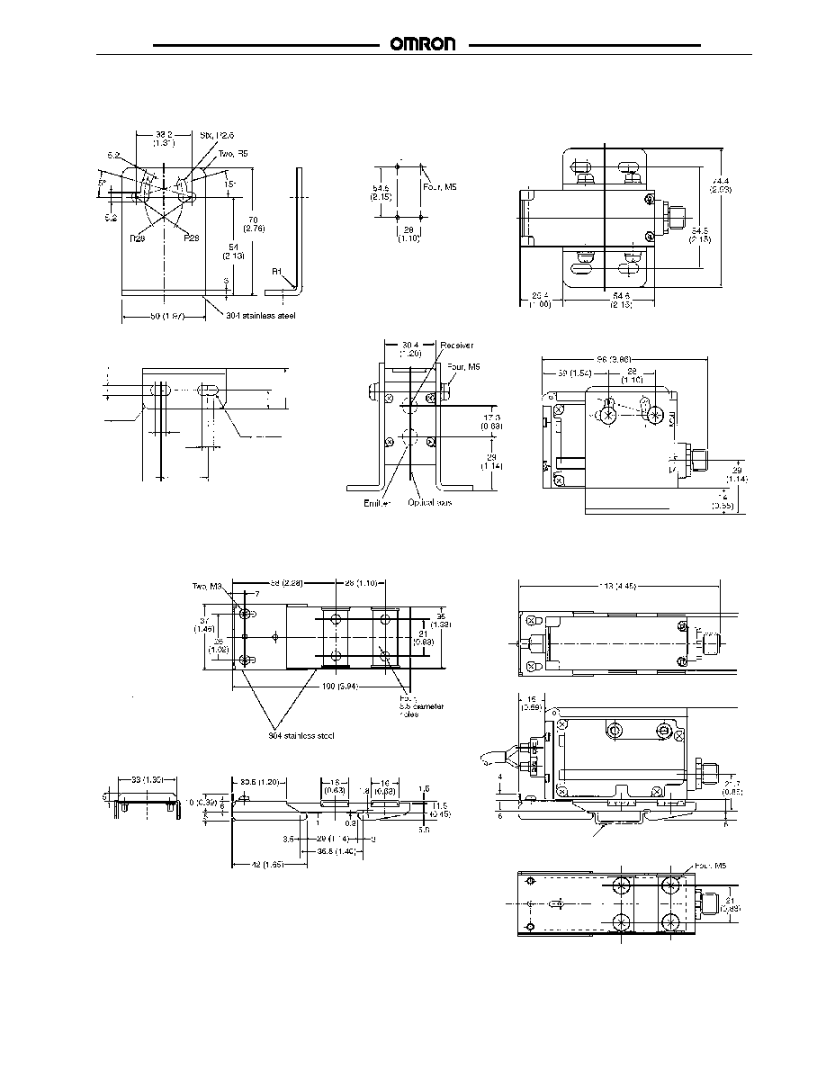
Dimensions
Unit: mm (inch)
RGB COLOR SENSORS
E3MC-A
E3MC-MA
Receiver
Emitter
Optical axis
Four, M5 holes on both
sides (depth: 5.5)
M12
connector
Four, M5 holes (depth: 5.5)
Mounting Dimension
Bottom Mounting
Two, 5.5-dia holes
Four, 5.5-dia holes
Two, M2.6 x 6
30.4
(1.19)
30
(1.18)
60 (2.36)
39
(1.53)
28
(1.10)
98 (3.85)
80 (3.14)
43
(1.69)
28
(1.10)
28
(1.10)
28
(1.10)
21 (0.82)
15.2
(0.59)
40.2
(1.58)
53.2
(2.09)
Side Mounting
15.2 (0.60)
17.3
(0.68)
Receiver
Emitter
Sensing face
(9.1 x 22.9)
Two, R1.65
mounting holes
Optical axis
3.3-dia. mounting holes
Sensing head
(heat-resistant ABS)
6-dia. optical fiber
(standard length: 1 m)
Fiber Head
Mounting Dimensions
Four, M5 holes on both
sides (depth: 5.5)
M12 connector
Four, M5 holes (depth: 5.5)
For Side Mounting --
Amplifier Unit
Bottom Mounting
Two, M2.6 x 6
Two, 5.5-dia holes
Four, 5.5-dia holes
Two, M3 holes
10.4
(0.41)
30.4
(1.20)
30
(1.18)
4
(0.16)
20
(0.79)
30
(1.18)
11.5 (0.45)
30
(1.18)
15.25
(0.60)
11.5
(0.45)
E3MC-X
E3MC-MX
8.9
(0.35)
8.5
(0.33)
98
(3.86)
80
(3.15)
39
(1.54)
28
(1.10)
28
(1.10)
43
(1.69)
40.2
(1.58)
53.2
(2.09)
15.2
(0.59)
28
(1.10)
28
(1.10)
21 (0.82)
Mounting Dimensions

E3MC
E3MC
Unit: mm (inch)
E3MC-Y
E3MC-MY
Four, M5 holes on both
sides (depth: 5.5)
M12 connector
Four, M5 holes (depth: 5.5)
Mounting Dimensions
(Amplifier Unit)
Side Mounting
Bottom Mounting
Two, M2.6 x 6
Two, 5.5-dia holes
Four, 5.5-dia holes
Two, 2.4 dia.
Receiver section
Emitter section
30.4
(1.20)
98
(3.86)
30
(1.18)
12.6
(0.50)
15.2
(0.60)
21 (0.83)
53.2
(2.09)
80
(3.15)
39
(1.54)
28
(1.10)
7.9
(0.31)
28
(1.10)
43
(1.69)
28
(1.10)
28
(1.10)
21 (0.83)
40.2
(1.58)
15.2
(0.60)
21 (0.83)
ACCESSORIES
Sensor I/O Connector
E39-C1 2M
E39-C1 5M
6
(0.25)
dia.
8.8
(0.35)
dia.
10.5
(0.41)
dia.
L
Standard length: 2 m
(Optional length: 5 m)
1.5
(0.06) 25.5
(1.0)
27
(1.06)
42
(1.65)
12
(0.47)
20
(0.79)
E3MC
E3MC
E39-L114 DIN Rail Side-Mounting Brackets
Mounting Holes
5.2
(0.20)
2-R5
4-R2.6
6.8
(0.27)
6.8
(0.27)
11
(0.43)
28
(1.10)
10
(0.39)
22
(0.87)
E39-L115 DIN Rail Mounting Bracket
DIN-rail
E3MC
E3MC
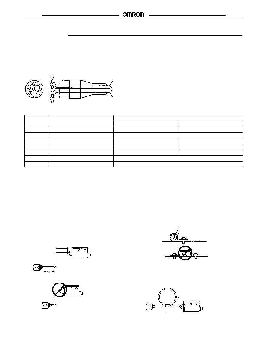
Installation
PLUG
Sensor I/O Connector
E39-C1 2M
E39-C1 5M
Internal Wiring
White
Brown
Green
Yellow
Pink
Blue
Lead wire color
Connection
Pin no.
Wire color
Purpose
E3MC-
11 or E3MC-
41
E3MC-M
11 or E3MC-M
41
E3MC-
11 or E3MC-
41
E3MC-M
11 or E3MC-M
41
1
White
Output
Output 1
2
Brown
Power supply (+V)
3
Green
Bank selection input 2
Output 4
4
Yellow
Bank selection input 1
Output 3
5
Gray
------
Output 2
6
Pink
External synchronous input
7
Blue
Power supply (0V)
FIBER UNIT
Tightening Torque
The Fiber Unit must be tightened to a maximum torque of 0.54 N
m (5.4 kgf
cm or 4.85 in
lbs).
Mounting
When Fiber Units are mounted facing each other, you must adjust the optical axes of the Fiber Units to avoid any mutual interference.
Handling the Fiber Unit
Sensor head
20 mm min.
20 mm min.
Amplifier Unit
Amplifier Unit
Sensor head
Correct
Incorrect
∑
Do not apply excess force to the Fiber Unit.
Fiber Unit
Nylon wire holder
Correct
Incorrect
∑
The Fiber Head could be broken by excessive vibration.
To prevent this, use a one-turn loop to absorb vibration,
as shown here:
A one-turn loop can
absorb vibration.
Tape
∑
Do not pull or press the Fiber Unit.
∑
Do not bend the Fiber Unit beyond the permissible bend-
ing radius provided in Ratings/Characteristics.
∑
Do not bend the edge of the Fiber Unit.

E3MC
E3MC
AMPLIFIER UNIT
Tightening Torque
The Amplifier Unit must be tightened to a maximum torque of
2.3 N
m (23 kgf
cm).
Mounting
When Sensors are mounted facing each other, you must adjust
the optical axes so that the Sensors will not cause mutual
interference.
GENERAL-PURPOSE FIBER-OPTIC
TYPE
Insertion
The inserted Fiber Unit comes in contact with the internal rubber
packing first. Insert the Fiber Unit further until it comes in contact
with the innermost end.
Mounting
Tighten the Fiber Unit with a screwdriver to a torque of 0.2 N
m
(2 kgf
cm).
Fibers
Among the recommended fibers, the E32-CC200 and E32-D32L
have white or dotted yellow lines on the fiber to be inserted into
the emitter. When using the E3MC-(M)Y
, insert the fiber with
the line into the emitter section at the bottom of the amp.
FIBER UNIT
Tightening Torque
When mounting the Fiber Unit, refer to the following table and
make sure that the tightening torque applied is correct.
Column Type
Screw-mounting Type
Mounting bracket
Toothed washer
Lock nuts (provided
with the E3MC)
Flat or pan head set screw (M3 max.)
Fiber Unit
Tightening torque
M3 screw
M4 screw
0.78 N
m {8 kgf
cm} max.
M6 screw
0.98 N
m {10 kgf
cm} max.
2-dia column
0.29 N
m {3 kgf
cm} max.
3-dia column
0.29 N
m {3 kgf
cm} max.
E32-T16
0.49 N
m {5 kgf
cm} max.
Make sure that the size of the wrench applied to the nut is correct.
Fiber Cutting
Insert the fiber into one of the insertion holes of the Cutting Tool to
cut the fiber to the desired length.
Press down the blade of the Cutting Tool to cut the fiber in a single
stroke. Do not stop the Cutting Tool midway.
View hole
Each insertion hole can be used only once. Do not use it again, or
the fiber may not be cut properly and the sensing distance may de-
crease.
E3MC
E3MC
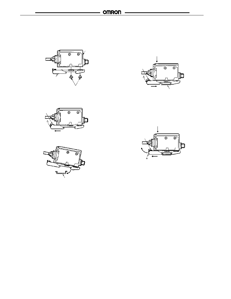
DIN-RAIL MOUNTING/REMOVAL WITH THE E39-L115
Mounting
1.
Attach the E39-L115 Mounting Bracket to the E3MC with four
M5 screws.
E3MC
E39-L115 Mounting Bracket
M5 screws
2.
When mounting the E3MC with the E39-L115, loosen the M3
screw of the E39-L115 and slide part A in the direction indi-
cated by arrow (1) as shown in the following illustration.
M3 screw
(1)
3.
Mount part (2) to the DIN rail.
DIN rail
(2)
4.
Press the E3MC in the direction indicated by arrow (3) and
slide part A in the direction indicated by arrow (4) as shown
in the following illustration until the E39-L115 correctly en-
gages with the DIN rail.
M3 screw
DIN rail
(3)
(4)
5.
Tighten the M3 screw of the E39-L115 to secure the
E39-L115.
Removal
Loosen the M3 screw of the E39-L115, press the E3MC in the
direction indicated by arrow (5) and slide part A in the direction
indicated by arrow (6). Then lift the E3MC up in the direction
indicated by arrow (7) to remove the E3MC with the E39-L115.
M3 screw
(5)
(6)
(7)

E3MC
E3MC
Terms
∑
Color Registration
Detection of a special mark on packaging material referred to
as the Registration Mark. This mark is aligned with the
printed pattern on the wrapping material and allows proper
cut-off of the packaging material so that printed images
appear in the correct location on the package.
∑
Conformity/Non-conformity
In the E3MC Color Sensor, term used to indicate when the
target color matches a reference color stored in the memory
bank(s). A match is "conformity," and a mismatch is
"non-conformity."
∑
D.O.
See Dark Operate.
∑
Dark Operate
Operating mode where the output is turned on (transistor
becomes conducting, or relay coil is energized) when light is
NOT received. In the E3MC Color Sensor, this refers to the
mode where the output turns on when the target color does
NOT match (non-conformity) the reference color stored in the
memory bank.
∑
Diffuse Reflective
Sensor configuration with the emitter and receiver located in
the same housing. Sensing of target is based on reflection of
light from the target itself (rather than a retroreflector).
∑
Excess Gain
See Stability Indicator.
∑
External Synchronous Input
In the E3MC Color Sensor, an input that allows "latching" of
the output when the input is taken high, preventing a change
of state until the input is taken low.
∑
IEC
International Electrotechnical Commission.
∑
Interference Protection
See Mutual Interference Protection.
∑
IP
International Protection; an international standard scale for
enclosure ratings (sealing).
∑
IP66
Approximately NEMA 4, 4X, "heavy seas" test; the item is
subjected to a stream of water from a
1
/
2
" nozzle with 14psi
pressure at a distance of 1.5 meter. Water must not enter the
item.
∑
IP67
Approximately NEMA 6, "immersion" test; the item is
immersed under 1 meter of water for 30 minutes, with no
water entry.
∑
kgf
Kilogram Force.
∑
kgf
cm
Kilogram-force centimeters, measure of torque;
1 kgf
cm = 10.4 in
lb.
∑
Lensed effect
Optical phenomenon where light passing through a
transparent object (bottle, for instance) is focused in the
same manner as a lens. If the lens effect is "converging," the
light intensity may be increased significantly. When sensing
the presence of an object due to the attenuation of light
passing through that object, the lens effect may cause a
failure to detect the object. The light intensity may not be
reduced due to the "lens" effect of concentrating the light
beam.
∑
L.O.
See Light Operate.
∑
Light Operate
Operating mode where the output is turned on (transistor
conducts, or relay coil is energized) when light is received. In
the E3MC Color Sensor, refers to the mode where the output
turns on when the target color matches (conforms) to the
reference color stored in the memory bank.
∑
Mutual Inference Protection
Circuitry that allows the sensor to detect and compensate for
interfering signals that may be emanating from sources within
its sensing range. Sensor can then operate normally, ignoring
the interfering signal(s).
∑
nm
Nanometer; a measure of length, 10
--9
meters, 3.937 x 10
--8
inches.
∑
NEMA
National Electrical Manufacturer's Association; industrial
trade organization that publishes testing standards, including
enclosure ratings.
∑
NPN
Transistor output designed to provide a path to ground for
current passing through the load ("sinking"). When the NPN
output is on, current can then pass from Positive, through the
load, and through the NPN transistor to ground, completing
the circuit.
∑
PNP
Transistor output that provides a path to "Plus" for current
passing through the load ("sourcing"). When the PNP output
is on, current can then pass from Positive, through the PNP
transistor, through the load, and to ground, completing the
circuit.
∑
Reflective Mode
See Diffuse Reflective.
∑
Response time
Elapsed time from when a target moves into the sensing
zone of a sensor to when the output turns on. May also refer
to the "turn-off" time. The sum of turn-on and turn-off time is
the total cycle time (reciprocal of switching frequency, Hz).
∑
Reverse Polarity Protection
Circuitry that prevents damage to the device if power is
incorrectly connected (polarity reversed, DC). The unit may
not work while polarity is reversed, but is undamaged, and
will work once polarity is corrected.
E3MC
E3MC
∑
RGB
Red, green, blue, refers to the triple light source in the E3MC
Color Sensor. By sensing the reflection level of each color,
the sensor can determine the exact color of the target.
∑
Short Circuit Protection
Circuitry that prevents damage to a device's output if the
output is short-circuited. Usually current is monitored, and the
output is turned off if current exceeds a predetermined value.
∑
Stability Indicator
Indicator light that shows when a signal being received (such
as a light beam) is strong enough for stable operation.
Usually this stable operation is expressed as a percentage
above the switching threshold of the device.
∑
Teach Function
Circuitry in a sensor that allows sensor threshold to be set
with the use of a "teach" input. Switching threshold is set
when the teach input is actuated, and it is based on signal
received at the moment of teaching.
∑
Through-beam
Sensor where the emitter and receiver are in separate
housings, and arranged facing each other. The target would
be detected passing between the emitter and receiver,
interrupting the beam.
Reference Information
WAVELENGTH
Color
Wavelength
Ultraviolet
below 400 nm
Violet
400--450 nm
Blue
450--500 nm
Green
500--570 nm
Yellow
570--590 nm
Orange
590--610 nm
Red
610--700 nm
Infrared
above 700 nm
CONVERSIONS
Length
1 inch = 25.4 mm
1 mm = 0.3937 inch
Torque
kgf
cm = 10.4 in
lb
1 in
lb = 0.096 kgf
cm
1 N
m = 8.974 in
lbs
Mass
1 gram = 2.205 x 10
--3
lbs
1 lb = 453.6 grams
Force
1 pound (force) = 4.4482219 Newtons
1 Newton = 0.2248 lb
force

E3MC
E3MC
Precautions
AVOID DAMAGE TO THE E3MC
∑
Voltage must not exceed the rated voltage of the E3MC.
∑
When supplying power to the E3MC, make sure that the
polarity of the power is correct.
∑
Do not short-circuit the load connected to the E3MC.
INSTALLATION
Power Up Ready
∑
The E3MC is ready to sense objects 100 ms after the unit is
turned ON.
∑
The 100 ms wait is also required when the E3MC output is
controlling other devices.
∑
If power is supplied to the E3MC and the load independently,
be sure to turn ON the E3MC
first.
∑
When the E3MC is turned ON or OFF, the operation indicator
will be illuminated for an instant, but no control output will be
turned ON.
Power Off
∑
The E3MC may output a single pulse when the control power
supply is turned OFF. If the E3MC is connected to a timer or
counter, you should supply power to the timer or counter from
the same power supply as the E3MC.
Power Supplies
∑
Power supply must be filtered with 10% MAX ripple (see
supply voltage specification).
∑
When a switching regulator is required, you must connect the
FG (frame ground) and G (ground) terminals together, eliminat-
ing the switching noise of the regulator to avoid a malfunction.
WIRING
Cable
∑
The cable can be extended up to 100 m, allowing for a cable
thickness of 0.3 mm
2
maximum.
∑
The cable must not be repeatedly bent.
∑
Do not pull cables with pulling forces exceeding 50 N
(11.24 lb
force).
M12 Metal Connector
∑
When connecting or disconnecting the cable, first remove the
power to the E3MC.
∑
To avoid damage, tighten the metal connector securely by
hand. Do
not use any tools.
∑
To ensure that the enclosure rating is maintained (so that
water/vibration ratings are assured), the cable connector
must be
securely hand-tightened.
Avoid Damage or Malfunction Due to Induction Noise
∑
Never run the E3MC Color Sensor cables in the same con-
duit with power lines or high tension cables.
FURTHER INFORMATION
Correcting an EEPROM Error
∑
An EEPROM error may result if the power supplied to the
Sensor fails, or if the Sensor is influenced by static noise.
When an EEPROM error occurs, the operation and bank
indicators will flash and the buzzer will beep. The remedy is
to reprogram and make threshold level settings again.

E3MC
E3MC
Cat. No. E256-E3-3
1/99
Specifications subject to change without notice.
Printed in U.S.A.
OMRON ELECTRONICS, INC.
One East Commerce Drive
Schaumburg, IL 60173
NOTE: DIMENSIONS SHOWN ARE IN MILLIMETERS. To convert millimeters to inches divide by 25.4.
1-800-55-OMRON
OMRON CANADA, INC.
885 Milner Avenue
Scarborough, Ontario M1B 5V8
416-286-6465