 | –≠–ª–µ–∫—Ç—Ä–æ–Ω–Ω—ã–π –∫–æ–º–ø–æ–Ω–µ–Ω—Ç: E3M-VG27 | –°–∫–∞—á–∞—Ç—å:  PDF PDF  ZIP ZIP |
Document Outline
- First Page
- Ordering Information
- Specifications
- Engineering Data
- Nomenclature
- Operation
- Dimensions
- Installation
- Precautions
- Contacting Omron
R
2
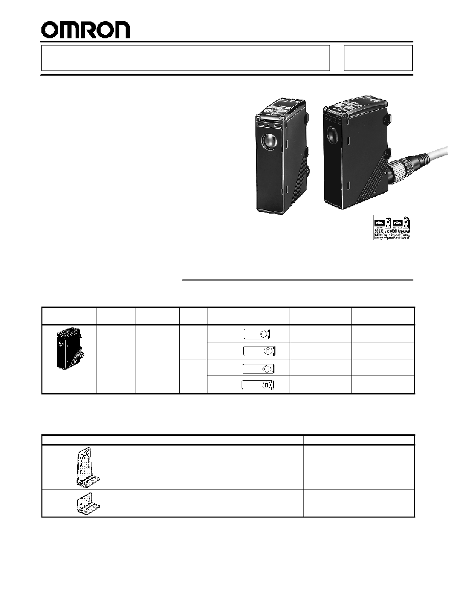
Color Mark Sensor with Teach Function
E3M-V
High-speed Registration Mark
Detection
H
Fast 50 µs response
H
Pushbutton programming for quick
setup
H
Remote control setup for on-the-fly
adjustments
H
Green LED detects yellow-on-white and
other difficult color combinations
H
Stable operation even on shiny surfaces
H
IP67 watertight construction
Ordering Information
J
SENSOR
Shape
Sensing
distance
Light source
Output
Spot size (W x H) and
orientation
Part number
(Quick-disconnect)
Part number
(Pre-leaded)
10 ±3 mm
Green LED
(525 nm)
NPN
1 x 4 mm
E3M-VG11
E3M-VG17
4 x 1 mm
E3M-VG21
E3M-VG27
PNP
1 x 4 mm
E3M-VG16
E3M-VG12
4 x 1 mm
E3M-VG26
E3M-VG22
J
MOUNTING BRACKETS
Order mounting brackets separately. These are not included with the sensor.
Shape
Part number
E39-L131
E39-L132

E3M-V
E3M-V
3
J
CONNECTING CABLES
Shape
Type
Conductors
Length
Part number
Straight
4-wire
2 meter (6.56 ft)
Y96E43SD2
5 meter (16.40 ft)
Y96E43SD5
L-shaped
2 meter (6.56 ft)
XS2F-D422-D80-A
p
5 meter (16.40 ft)
XS2F-D422-G80-A
Specifications
J
RATINGS/CHARACTERISTICS
Part number
E3M-VG11
E3M-VG21
E3M-VG16
E3M-VG26
Method of detection
Diffuse type
Supply voltage
10 to 30 VDC, 10% ripple max. (p--p)
Current consumption
100 mA max.
Sensing distance
10 ± 3 mm
Spot size (W x H) and orientation 1 x 4 mm
4 x 1 mm
1 x 4 mm
4 x 1 mm
Spot size (W x H) and orientation 1 x 4 mm
4 x 1 mm
1 x 4 mm
4 x 1 mm
Light source (wavelength)
Green LED, 525 nm
Output
NPN open collector
PNP open collector
Output
Residual voltage: 1.2 V max.
Residual voltage: 2 V max.
100 mA load, 30 VDC max.
Light-ON/Dark-ON switch selectable
Short-circuit protected
Response time
ON: 50 µs max.
OFF: 70 µs max.
Remote control input
(See Note.)
ON: Short-circuited to 0 or 1.5 V max., leakage
current of 1 mA max.
OFF: Open or V
CC
--1.5 V to V
CC,
leakage
current of 0.1 mA max.
ON: V
CC
--1.5 V to V
CC,
leakage current of
3 mA max.
OFF: Open or 1.5 V max., leakage current of
0.1 mA max.
Remote control output
30 VDC max., 100 mA max.
Remote control output
(See Note.)
NPN open collector, residual voltage: 1.2 V max. PNP open collector, residual voltage: 2 V max.
Bank selection
Two banks selectable. Available for remote control only.
Circuit protection
Protection from reversed polarity connection and load short-circuit
Ambient light immunity
Incandescent lamp: 3,000 x max. Sunlight: 10,000 x max.
Ambient
Operating
--20∞C to 55∞C (--4∞F to 131∞F) with no icing
Ambient
temperature
Storage
--30∞C to 70∞C (--22∞F to 158∞F) with no icing
Ambient humidity
Operating
35% to 85% RH with no condensation
Ambient humidity
Storage
35% to 95% RH with no condensation
Insulation resistance
20 M min. (at 500 VDC)
Dielectric strength
1,000 VAC, 50/60Hz, 1 min.
Vibration resistance
10 to 55 Hz, 1-mm double amplitude or 150 m/s
2
for 2 hrs each in X, Y, and Z axes
With bracket attached: 0.75-mm double amplitude or 100 m/s
2
Shock resistance
500 m/s
2
3 times each in X, Y, and Z axes. With bracket attached: 300 m/s
2
Enclosure rating
IP67 IEC60529 (with cover properly closed)
Connection method
Quick-disconnect M12
Weight
Approx. 100 g (with carton)
Material
Case:Polybutylene terephthalate
Lens: Acrylic (PMMA)
Included
Instruction manual
Note: Remote control input and answer-back output share the same signal line.
E3M-V
E3M-V
4
Engineering Data
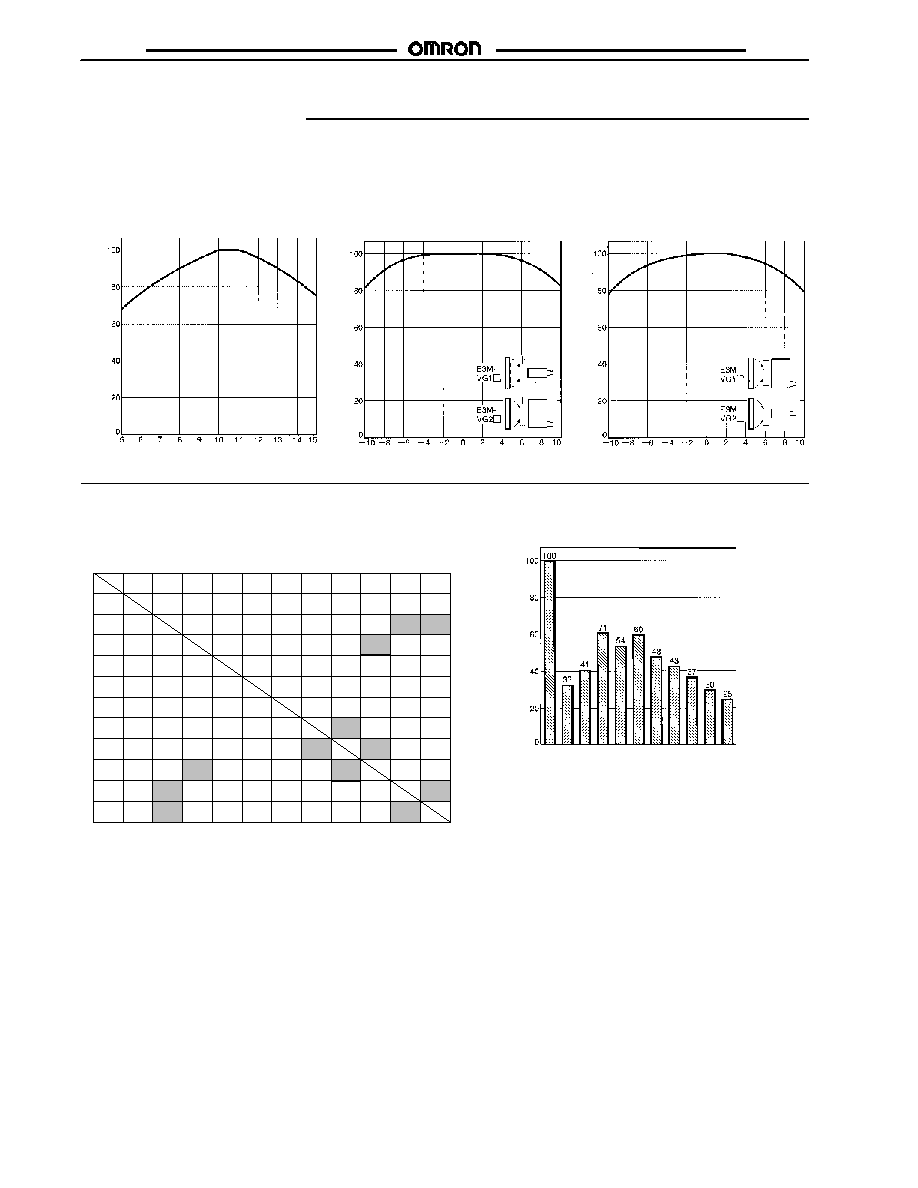
J
SENSING DISTANCE VS.
INCIDENT CHARACTER-
ISTICS (TYPICAL)
E3M-VG1j
J
ANGLE VS. INCIDENT
CHARACTERISTICS
(X DIRECTION)
E3M-VG1j/VG2j
J
ANGLE VS. INCIDENT
CHARACTERISTICS
(Y DIRECTION)
E3M-VG1j/VG2j
I
n
c
i
denc
e
(
%
)
Distance (mm)
Angle (∞)
Angle (∞)
I
n
c
i
denc
e
(
%
)
I
n
c
i
denc
e
(
%
)
J
COLOR SENSING BACKGROUND VS.
COLOR MARK
E3M-VGjj
White
Yellow
green
Red Yellow
red
Yellow
Green Blue
green Blue Purple
Red
purple Black
White
Red
Yellow
red
Yellow
Green
yellow
Green
Black
Red
purple
Purple
Blue
Blue
green
f
f
f
f
f
f
f
f
f
f
f
f
f
f
f
f
f
f
f
f
f
f
f
f
f
f
f
f
f
f
f
f
f
f
f
f
f
f
f
f
f
f
f
f
f
f
f
f
f
f
f
f
f
f
f
f
f
f
f
f
f
f
f
f
f
f
f
f
f
f
f
f
f
f
f
f
f
f
f
f
f
f
f
f
f
f
f
f
f
f
f
f
f
f
f
f
f
: Detectable n: Detectable but unstable X: Not detectable
J
DIFFERENCES IN INCIDENT
BY COLOR
I
n
c
i
denc
e
(
%
)
X
n
X
X
n
n
f
n
n
f
X
n
X
X
Wh
i
t
e
Red
Y
e
llow
r
ed
Y
e
llow
Y
e
llow
g
r
een
G
r
een
B
l
ue
gr
een
Bl
u
e
Pu
rp
l
e
Red
pur
ple
Bl
a
c
k Color
E3M-V
E3M-V
5
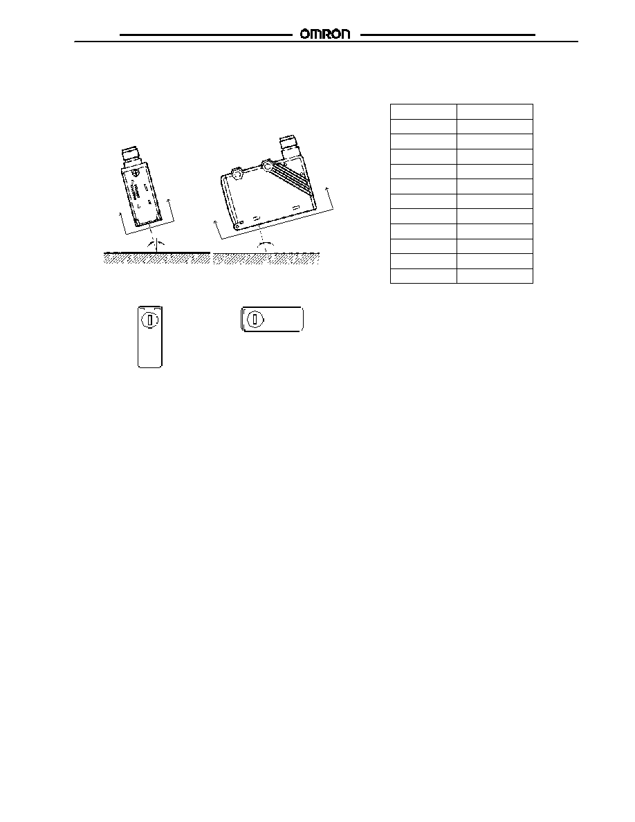
J
STANDARD TARGET OBJECT
(COLOR VS. MUNSELL)
Munsell color notation
11 standard colors
White
Red
Yellow red
Yellow green
Yellow
Green
Blue green
Blue
Purple
Red purple
N9.5
4R, 4.5/12.0
4YR, 6.0/11.5
5Y, 8.5/11.0
3GY, 6.5/10.0
3G, 6.5/9.0
5BG, 4.5/10.0
3PB, 5.0/10.0
7P, 5.0/10.0
6RP, 4.5/12.5
Black
N2.0
J
INSTALLATION
Glossy Target Objects
Incline the Sensor for glossy objects to reduce mirror reflection for
stable sensing operation.
Target object
Target object
5 to 15∞
5 to 15∞
A
A
B
B
E3M-VG1j
E3M-VG2j
View AA
View BB
E3M-V
E3M-V
6
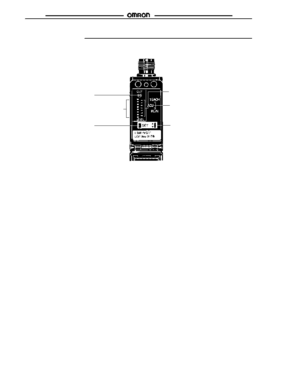
Nomenclature
J
E3M-V SENSOR
Operation Indicator (Orange)
Lit when the output is ON.
Detection Level Indicators (Green)
Displays the detection level.
SET Button
Used for teaching and threshold
adjustments.
Threshold Indicators (Red)
Displays the threshold level.
Mode Selector
Selects the mode.
UP/DOWN Selector
Increases the threshold value when
set to UP.
Decreases the threshold value when
set to DOWN.
E3M-V
E3M-V
7
Operation
J
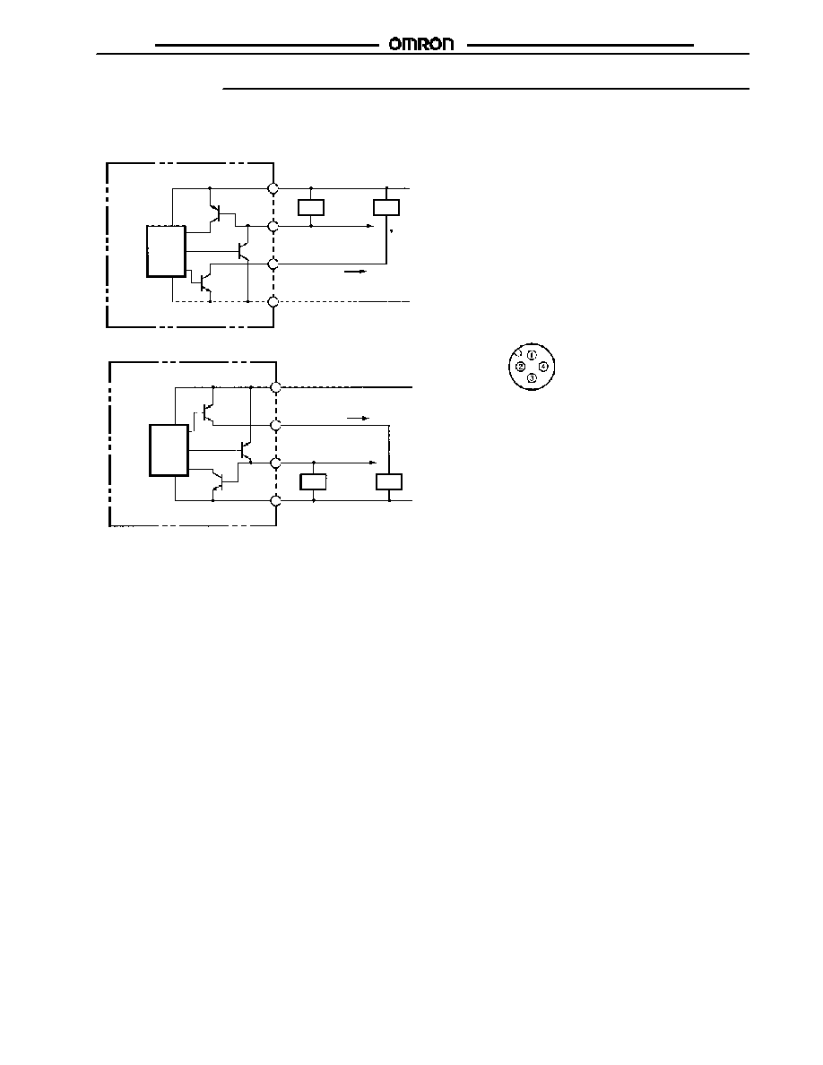
OUTPUT CIRCUITS
Main
circuit
Remote control input
/Answer-back output
Load
Load
Control
output
Brown
White
Black
Blue
Main
circuit
Load
Load
10 to 30 VDC
Control
output
Brown
White
Black
Blue
(See note.)
(See note.)
Remote control input
/Answer-back output
NPN (E3M-VG11, E3M-VG21)
PNP (E3M-VG16, E3M-VG26)
10 to 30 VDC
Connector Pin Arrangement
1
2
4
3
1
4
2
3
100 mA max.
0 V
0 V
Note: Remote control input and answer-back output share the same line. Be sure to connect the load as shown above if the remote con-
trol function is used.
E3M-V
E3M-V
8
J
OPERATING PROCEDURE
Adjustment Steps
1. Install, wire, and turn ON the E3M-V.
2. Perform teaching (mark registration). Refer to Mark Registration (Teaching).
3. Make fine adjustments of the threshold level if necessary. Refer to Threshold Level Adjustments.
4. Check that the mode selector is set to RUN.
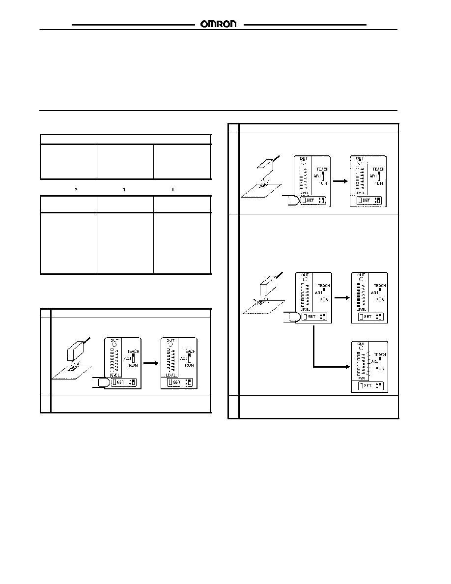
Mark Registration (Teaching)
Refer to the following for ideal teaching.
Application
The base has a
color pattern. The
mark and base are
clearly different in
color.
The base has no
color pattern. The
mark and base are
slightly different in
color.
The base has no
color pattern.
Remote teaching
with no positioning
is desired.
One-point teaching
Two-points
teaching
Auto-teaching
The default level is
set and the output
is ON when the
mark is detected.
The threshold level
is set between the
color of the mark
and base. The
output is ON when
the mark is
detected.
The threshold level
is set between
color of the mark
and base. The
output is ON when
the mark (i.e., the
color with shorter
passing time) is
detected.
Refer to the following for each teaching method. Remote one- or
two-point teaching is possible. Refer to Remote Control Function.
One-point Teaching
1
Set the mode selector to TEACH.
2
Locate the mark to the sensing position and press the SET
button. Then all the red threshold indicators are ON.
Mark
Sensor
Base
Push
Red threshold indicators are ON
3
Set the mode selector to RUN. The output will be ON
whenever the set mark is detected.
Note: By teaching on the base, reversed output as shown above
(base: ON, mark: OFF) can be obtained.
Two-point Teaching
1
Set the mode selector to TEACH.
2
Locate the mark to the sensing position and press the SET
button. All the red threshold indicators will turn ON.
Mark
Sensor
Push
Red threshold indicators are ON.
Base
3
Mark
Sensor
Push
If teaching is successful, move the mark and press the
SET button at the base.
∑
If teaching is successful, all the green detection level
indicators are ON.
∑
If teaching is unsuccessful, all the red threshold level
indicators flash.
Teaching
is OK
Green detection level
indicators are ON.
Teaching is NG
All the red threshold level
indicators will flash if there
is no difference in incident.
Base
4
If teaching is successful, set the mode selector to RUN to
complete the teaching operation. If teaching is
unsuccessful, restart from the above step 2.
Note: Follow the above steps so that the output will be turned
ON whenever the mark is detected. By taking the opposite
steps, the output will be turned OFF whenever the mark is
detected and turned ON whenever the base is detected.
E3M-V
E3M-V
9
J
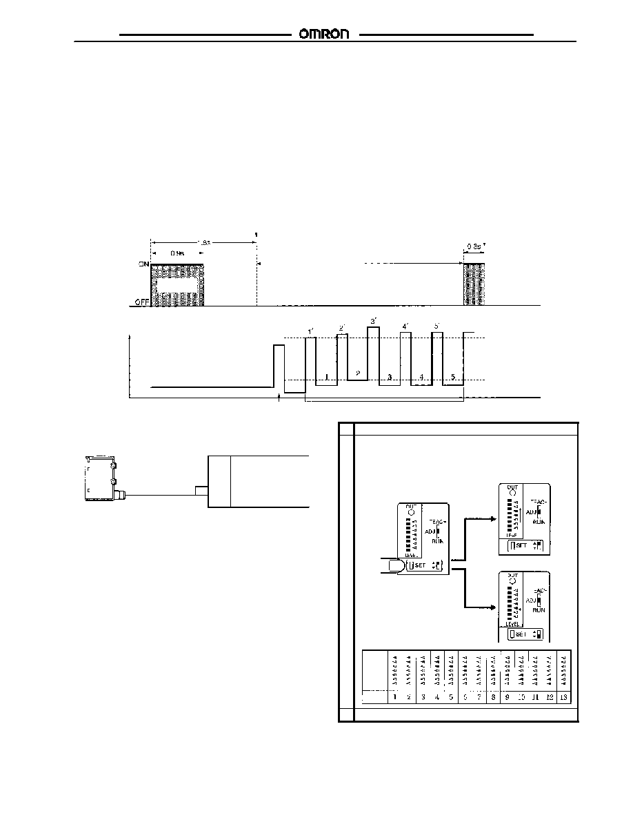
ADJUSTMENT STEPS
Auto-teaching
1. Check that the mode selector is set to either RUN or ADJUST.
2. Input a 0.9-s pulse signal into the remote control I/O terminal. (See Note.)
3. Auto-teaching starts when the mark is moved. When the mark passes six times, auto-teaching completes.
∑
If teaching is successful, answer-back output from the remote control I/O terminal will turn ON for 0.3 s.
∑
If teaching is unsuccessful, no answer-back signal will be output. Readjust using two-point teaching.
(Teaching will be unsuccessful if there is no difference in incident between the mark and base.)
4. If the answer-back signal is ON, the whole teaching operation will be completed. The output will be turned ON whenever the mark
(i.e., the color with shorter passing time) is detected.
Note: Make sure that the input tolerance of each pulse is within ±0.1 s.
Auto-teaching Illustration
Remote control input/
Answer-back output
Incident
Auto-teaching
Teaching starts
Teaching completes and detection starts
Answer-back
Time
Mark (shorter passing time):
Output ON
Optimal threshold level set
Base: Output OFF
Dummy sampling (1st mark)
Sampling (5th mark)
Time
Example of Connection to Programmable Controller
Sensor
Remote control I/O
I/O Unit
Programmable Controller
Output
Input
Note: Be sure to connect the E3M-V to the Programmable Con-
troller as shown above.
Precautions when Using Automatic Teaching
Incorrect discrimination may be caused by automatic teaching in
the following cases. Use one-point or two-point teaching in such
cases.
∑
Color patterns exist in the base.
∑
Sensing objects change their positions.
∑
Sensing objects have protrusions or surface level differences.
Threshold Level Adjustments
It is possible to make fine adjustments of the threshold level after
teaching. Such fine adjustments can be made remotely as well.
Refer to Remote Control Function.
1
Set the mode selector to ADJUST.
2
Select the upper or lower threshold setting with the thresh-
old selector. Whenever the SET button is pressed, the
threshold level will move. Two indicators will be lit together
when the threshold level is an even level.
The threshold level increases.
The threshold level decreases.
Lower
threshold
limit
Press
Upper
threshold
limit
Threshold
indicators
Threshold
level
3
After setting the level, set the mode selector to RUN.
E3M-V
E3M-V
10
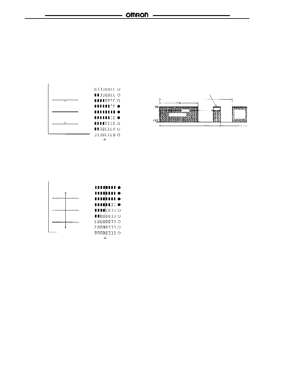
Detection Level Indicator
The control output of the E3M-V will be turned ON if the detection
level exceeds the threshold level. The indication of the detection
level varies with the teaching method.
One-point Teaching
The upper and lower threshold values are set on the basis of the
mark and the detection level indicators indicate the degree of
color conformity to the mark's color.
Detection level
Output OFF
Output ON
Threshold
value
Mark
Output OFF
Detection
level indi-
cators
Operation
indicator
Threshold value
Threshold
value
Two-point or Auto-teaching
A single threshold value is set between the mark (registered first)
and the base (registered next). The detection level indicators
indicate the tolerance between the mark and base.
Detection level
Output OFF
Output ON
Threshold
value
Mark
Detection
level indi-
cators
Operation
indicator
Threshold value
Base
Remote Control Function (Bank Selection, Mark
Registration, and Threshold Adjustments)
Under Run Mode or Adjust Mode
The input of any of the signals listed in the following table into the
remote control I/O terminal allows remote control of the E3M-V.
When the signal is accepted, answer-back output will be turned
ON for 0.3 s. Only in the case of one-point teaching, however,
can the signal be manually input, provided that the input is ON for
1.5 s or more.
Timing Chart
Remote
control I/O
Sensor
operation
Input signal
Answer-back output: ON
only when the process
completes normally.
Detection restarts
Setting
change
Input discrimination
(1.8 s)
2.5 s min.
Next
input
signal
2.0 s
0.3 s
Note: If signals are sent continuously, make sure that there is an
interval of 2.5 s between signal inputs as shown above.

E3M-V
E3M-V
11
Control Signals
No. Control signal
Function
1
Bank 1 is selected
(operation indicator OFF in
TEACH mode)
2
Bank 2 is selected
(operation indicator ON in
TEACH mode)
3
Auto-teaching
4
Two-point teaching
(1st and 2nd)
5
One-point teaching
(or input for 1.5 s min.)
6
Threshold level 1 is
selected.
7
Threshold level 3 is
selected.
8
Threshold level 5 is
selected.
9
Threshold level 7 is
selected.
10
Threshold level 9 is
selected.
11
Threshold level 11 is
selected.
12
Threshold level 13 is
selected.
Note: The input error of each signal pulse must be within ±0.1 s.
Ladder Program Example
Control signals are input by a ladder program as shown below.
Input: 00000
Output: 00100
Others: IR bits
TIM000, TIM001, and TIM002
set values
E3M-V
E3M-V
12
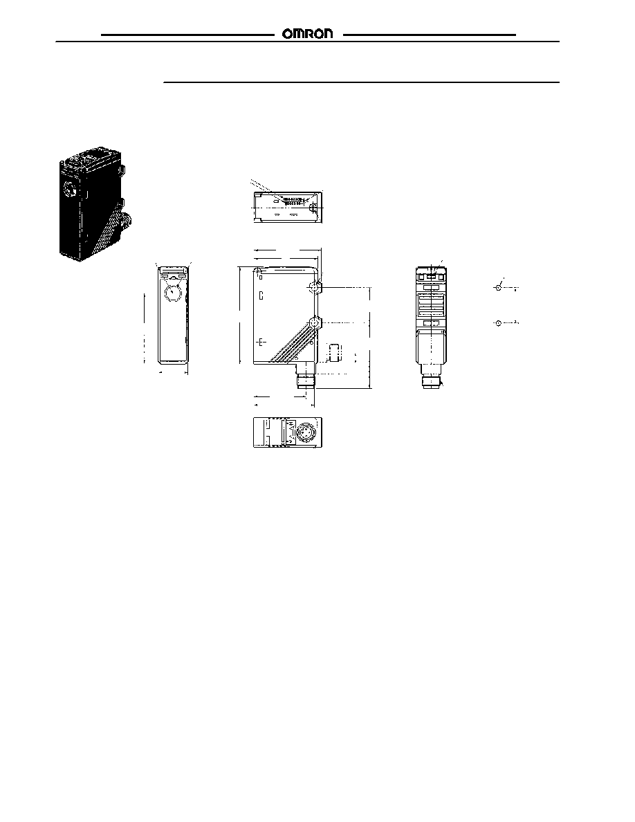
Dimensions
Unit: mm (inch)
J
COLOR MARK SENSORS
Eight detection level indicators
Seven level threshold indicators
Operation indicator
M2.6 nut
M12 Connector
M2.6
10 (0.39) dia. lens
Optical axis
Two, 4.5 dia.
mounting holes
Mounting Holes
Two, M4
50
(1.97)
21
(0.83)
47.7
(1.88)
45
(1.77)
25
(0.98)
25
(0.98)
29
(1.14)
7
(0.28)
10
(0.39)
37
(1.46)
43
(1.69)
68.5
(2.70)
E3M-V
E3M-V
13
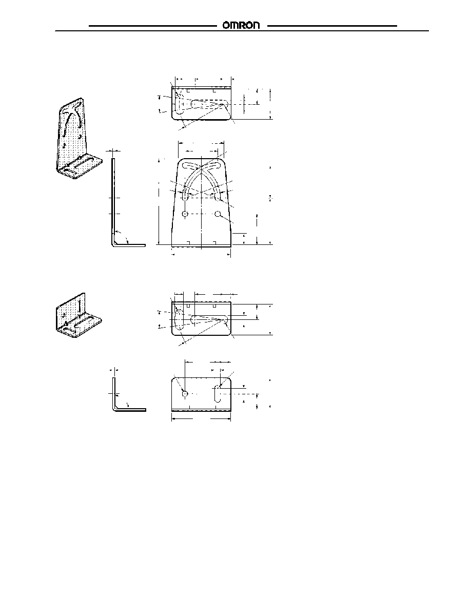
J
MOUNTING BRACKETS
E39-L131
E39-L132
Two,
4.2 dia.
4.2 dia.
Material: Stainless steel (SUS304)
Material: Stainless steel (SUS304)
22
(0.87)
5.5
(0.22)
23.5
(0.93)
11.5
(0.45)
2-R3.2
6.4 (0.25)
R34
15∞
90∞ ±
0.1
2-R3.2
6.4
(0.25)
35
(1.38)
4-R1
R25
4-R2.1
25 ±
0.1
(0.98 ±
0.004
)
35.5
(1.40)
23.5
(0.93)
45
(1.77)
65.5
(2.58)
R25
4.2
(0.17)
4.2
(0.17)
25 ±
0.1
(0.98 ±
0.004
)
8.5 (0.33)
1.5
(0.06)
15∞
90∞ ±
0.1
22
(0.87)
5.5
(0.22)
23.5
(0.93)
11.5 (0.45)
2-R3.2
6.4 (0.25)
R34
2-R3.2
6.4
(0.25)
1.5
(0.06)
23.5
(0.93)
11.5 (0.45)
8.5 (0.33)
45
(1.77)
25 ±
0.1
(0.98 ±
0.004
)
10
(0.39)
2-R2.2
4.4
(0.17)
E3M-V
E3M-V
14
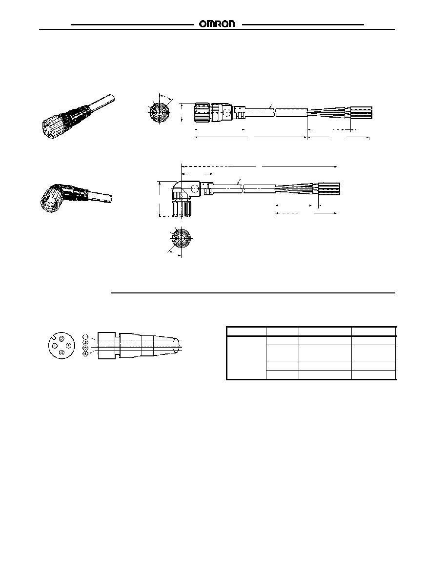
J
SENSOR CABLES
Single-end Connector (Straight Model)
Single-end Connector (L-shaped Model)
XS2F-D422-D80-A (2 m)
XS2F-D422-G80-A (5 m)
5 (0.20)
dia.
14.9 (0.59)
dia.
6 (0.24) dia.
Y96E43SD2 (2 m)
Y96E43SD5 (5 m)
40.7
(1.60)
M12
45∞
50
(1.97)
L
30
(1.18)
5
(0.20)
6 (0.24) dia.
5 (0.20)
dia.
50
(1.97)
30
(1.18)
5
(0.20)
L
25.3
(1.00)
28.3
(1.11)
M12
45∞
Installation
J
SENSOR CABLE
Pin No.
Cord wire colors
DC/AC
Brown
Blue
Black
Classification Wire color Connector pin No. Use
DC
Brown
1
(+V)
DC
White
2
Remote
control
Blue
3
(0V)
Black
4
Output

E3M-V
E3M-V
Precautions
J
SAFETY
Observe the following precautions to ensure safety.
∑
Do not use the Sensor in locations subject to flammable or
explosive gases.
∑
Do not use the Sensor in water or conductive solution.
∑
Do not disassemble, repair, or modify the Sensor.
∑
Use the Sensor under proper power supply specifications
such as the use of AC or DC power supply.
∑
Do not apply any voltage or current exceeding the rated level.
∑
Be careful with the power supply polarities and wire correctly.
∑
Connect the loads correctly.
∑
Do not short-circuit both ends of loads.
J
INSTALLATION AND USE
Power Reset Time
Since the E3M-V is ready to detect objects from 100 ms max.
after the E3M-V is turned ON, operate the remaining devices
100 ms after the Sensor is turned ON. If power is supplied to the
E3M-V and the load independently, be sure to turn on the E3M-V
first.
Power OFF
The E3M-V may output a single pulse when the control power
supply is turned OFF. If the E3M-V is connected to a timer or
counter to which power is supplied from an independent power
supply, the E3M-V will be more likely to output a single pulse
when the control power supply is turned OFF. For this reason,
supply power to the timer or counter from the same power supply
for the E3M-V.
Power Supply Type
Supply voltage ripple must not exceed rated percentage.
Power Supply Connection
Be sure to ground the FG (frame ground) and G (ground)
terminals if a switching regulator is connected to the E3M-V to
avoid malfunction due to the switching noise of the switching
regulator.
J
WIRING
Cable
∑
The cable can be extended up to 100 m provided that the
thickness of the cable is 0.3 mm
2
minimum.
∑
The cable must not be bent repeatedly.
∑
Do not pull cables with pulling forces exceeding 50N
(11.24 lb).
High-tension Lines
To avoid damage and malfunctioning due to induction noise, wire
sensor power lines in a separate conduit from any power lines or
high tension lines.
J
MOUNTING
Screw Tightening
Make sure that the casing is tightened to a maximum torque of
1.2 N S m.
Mounting Direction
When Sensors are mounted to face each other, make sure to
adjust the optical axes to avoid mutual interference.
J
EEPROM WRITE ERROR
An EEPROM error may result if power supply to the Sensor fails
or the Sensor is influenced by static noise, and the threshold
level indicators will flash. Perform the teaching and threshold
level setting of the E3M-V again.
J
M12 METAL CONNECTOR
∑
Turn off the E3M-V before connecting or disconnecting the
metal connector.
∑
Make sure to hold the connector cover when connecting or
disconnecting the metal connector.
∑
Tighten the metal connector securely by hand. To avoid dam-
age, do not use any tool, such as pliers.
∑
If the metal connector is not tightened securely, it may be
disconnected by vibration, and the proper degree of protec-
tion of the E3M-V may not be maintained.
Cat. No. CEDSAX4 11/01 Specifications subject to change without notice. Printed in U.S.A.
OMRON ELECTRONICS LLC
One East Commerce Drive
Schaumburg, IL 60173
NOTE: DIMENSIONS SHOWN ARE IN MILLIMETERS. To convert millimeters to inches divide by 25.4.
1-800-55-OMRON
OMRON CANADA, INC.
885 Milner Avenue
Scarborough, Ontario M1B 5V8
416-286-6465
R
OMRON ON--LINE
Global -- http://www.omron.com
USA -- http://www.omron.com/oei
Canada -- http://www.omron.com/oci