Document Outline
- GENERAL-PURPOSE PHOTOELECTRIC SENSOR E3S-A
- Ordering Information
- Specifications
- Engineering Data
- Dimensions
- Operation
- Contacting Omron

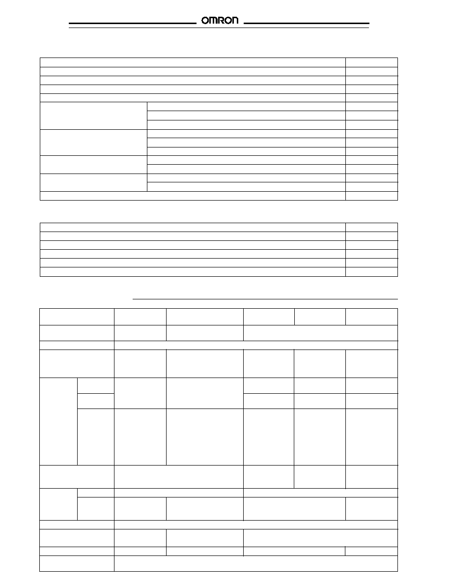
Method of detection
Through-beam
Retroreflective
Diffuse reflective
Sensing distance
7 m (22.97 ft)
2 m (6.56 ft)
10 cm (3.94 in) 20 cm (7.87 in) 70 cm (2.3 ft)
Mounting
Output
Extra features
Connection
Part number
Horizontal NPN
None
Prewired
E3S-AT11
E3S-AR11
E3S-AD13
E3S-AD11
E3S-AD12
None
Connector
E3S-AT16
E3S-AR16
E3S-AD18
E3S-AD16
E3S-AD17
Timer,
Prewired
E3S-AT21
E3S-AR21
E3S-AD23*
E3S-AD21
E3S-AD22*
alarm and turbo
PNP
None
Prewired
E3S-AT31
E3S-AR31
E3S-AD33
E3S-AD31
E3S-AD32
None
Connector
E3S-AT36
E3S-AR36
E3S-AD38
E3S-AD36
E3S-AD37
Timer,
Prewired
E3S-AT41
E3S-AR41
E3S-AD43*
E3S-AD41
E3S-AD42*
alarm and turbo
Vertical
NPN
None
Prewired
E3S-AT61
E3S-AR61
E3S-AD63
E3S-AD61
E3S-AD62
None
Connector
E3S-AT66
E3S-AR66
E3S-AD68
E3S-AD66
E3S-AD67
Timer,
Prewired
E3S-AT71
E3S-AR71
E3S-AD73*
E3S-AD71
E3S-AD72*
alarm and turbo
PNP
None
Prewired
E3S-AT81
E3S-AR81
E3S-AD83
E3S-AD81
E3S-AD82
None
Connector
E3S-AT86
E3S-AR86
E3S-AD88
E3S-AD86
E3S-AD87
Timer,
Prewired
E3S-AT91
E3S-AR91
E3S-AD93*
E3S-AD91
E3S-AD92*
alarm and turbo
*10 and 70 cm diffuse versions do not have turbo function
Sensing
Supply voltage
Output
10 to 30 VDC
7 m
2 m
20 cm, 70 cm
100 mA
Wide Selection of High Performance Small DC
Sensors Offers Longer Sensing Distances
s
Fast 0.5 msec response time for
high-speed sensing
s
Extended sensing distances up to 7 meters
s
Self-diagnostic functions available
s
User-friendly features for easy installation
and use
s
Meets: NEMA 4X, 6 and IP67
s
Many mounting configurations available
s
Choose prewired or connector-ready models
s
E3S-AD Series includes 10 cm short range
diffuse version
General-Purpose Photoelectric Sensor
E3S-A
s
SENSORS
Ordering Information
Through-beam sensors include both emitter and receiver. The polarized retroreflective sensors include E39-R1 reflector. All sensors
include mounting hardware. Optional mounting brackets are available as accessories.
2
E3S-A
E3S-A
Part number
E3S-AT
uu
E3S-AR
uu
E3S-AD
u
3,
E3S-AD
u
1,
E3S-AD
u
2,
E3S-AD
u
8
E3S-AD
u
6
E3S-AD
u
7
Method of detection
Through-beam
Polarized
Diffuse reflective
retroreflective
Supply voltage
10 to 30 VDC,
�
10%
Current consumption
40 mA max.
30 mA max.
35 mA max.
30 mA max.
35 mA max.
(emitter and
45 mA with turbo
45 mA with turbo
receiver)
55 mA with turbo
Sensing
White
0 to 7 m
0.1 to 2 m with E39-R1
0 to 10 cm
0.1 to 20 cm
0 to 70 cm
distance
mat paper
(0 to 22.97 ft)
(0.33 to 6.56 ft)
(0 to 3.94 in)
(0.04 to 7.87 in)
(0 to 27.56 in)
Black
0.3 to 2.5 cm
0.5 to 2.3 cm
0.15 to 33 cm
mat paper
(0.12 to 0.98 in)
(0.20 to 0.91 in)
(0.06 to 12.99 in)
With
2.4 m (7.87 ft)
10 to 130 cm with E39-R3
--
--
--
accessories
with E39-E6
(3.94 to 51.18 in)
2.5 m (8.20 ft)
7 to 60 cm with E39-R4
with 2 mm slit
(2.76 to 23.62 in)
1.1 m (3.61 ft)
10 to 30 cm with E39-RSA
with 1 mm slit
(3.94 to 11.81 in)
0.5 m (1.64 ft)
10 to 60 cm with E39-RSB
with 0.5 mm slit
(3.94 to 23.62 in)
Light source
Pulse modulated red LED (700 nm)
Pulse modulated
Pulse modulated
Pulse modulated
infrared LED
red LED
infrared LED
(880 nm)
(700 nm)
(880 nm)
Standard
Type
Opaque materials
Opaque and transparent materials
object
Size
7 mm (0.28 in)
30 mm (1.18 in)
10 x 10 cm (3.94 x 3.94 in)
20 x 20 cm
minimum
minimum
white mat paper
(7.87 x 7.87 in)
white mat paper
Operation mode
Light-ON/Dark-ON operation, switch selectable
Variation in
--
--
+30% max., �0% max.
sensing distance
Hysteresis
--
--
10% max.
20% max.
Variation in optical axis
�
2
�
max.
and mounting direction
s
ACCESSORIES
Description
Part number
Mounting bracket for vertical sensors (2 required for through-beam type)
E39-L59
Slits for E3S-AT
uu
sensors (3 pairs: 2 mm, 1 mm and 0.5 mm wide, includes mounting hardware)
E39-S46
Mutual interference filters for E3S-AT
uu
sensors (2 pairs: horizontal and vertical, includes mounting hardware)
E39-E6
Optical alignment reflector for E3S-AT
uu
E39-R5
2 m (6.56 ft) cable
Y96E-43SD2
5 m (16.40 ft) cable
Y96E-43SD5
10 m (32.81 ft) cable
Y96E-43SD10
2 m (6.56 ft) cable
Y96E-43RD2
5 m (16.40 ft) cable
Y96E-43RD5
10 m (32.81 ft) cable
Y96E-43RD10
Small corner cube reflector
10 to 130 cm (3.94 to 51.18 in)
E39-R3
7 to 60 cm (2.76 to 23.62 in)
E39-R4
Adhesive back reflector
10 to 30 cm (3.94 to 11.81 in)
E39-RSA
10 to 60 cm (3.94 to 23.62 in)
E39-RSB
Mounting bracket for E39-R1 reflector
E39-L7
Straight connector cordsets
(4-pole female connector)
Right-angle connector cordsets
(4-pole female connector)
s
REPLACEMENT PARTS
Description
Part number
Knob for sensitivity adjuster
E39-G2
Mounting bracket spacer for connector versions
E39-L60
Corner cube reflector (supplied with E3S-AR
uu
)
E39-R1
Mounting bracket for horizontal sensors (supplied with each sensor)
E39-L69
Mounting bracket for vertical sensors (supplied with each sensor)
E39-L70
Specifications
3
E3S-A
E3S-A
Part number
E3S-AT
uu
E3S-AR
uu
E3S-AD
u
3,
E3S-AD
u
1,
E3S-AD
u
2,
E3S-AD
u
8
E3S-AD
u
6
E3S-AD
u
7
Sensitivity
Adjustable, 2-turn knob with clutch and indicator
Mutual interference
Not provided
Provided
Provided
Provided
Provided
protection
Control
Type
NPN transistor, open collector (E3S-A
u
1
u
, E3S-A
u
2
u
, E3S-A
u
6
u
, E3S-A
u
7
u
),
output
(E3S-AD1
u
, E3S-AD2
u
, E3S-AD6
u
, E3S-AD7
u
)
PNP transistor, open collector (E3S-A
u
3
u
, E3S-A
u
4
u
, E3S-A
u
8
u
, E3S-A
u
9
u
),
(E3S-AD3
u
, E3S-AD4
u
, E3S-AD8
u
, E3S-AD9
u
)
Max. load
100 mA max. at 30 VDC
Max.
1 VDC max. at 100 mA load current
ON-state
voltage drop
Self-diagnostics
50 mA max. load at 30 VDC, NPN or PNP transistor open collector to match control output
alarm output
Response time
0.5 ms max. ON, 0.5 ms max. OFF
OFF-delay timer
0 to 100 ms with 3/4 turn adjuster
Check
NPN
Light OFF: gray wire connected to 0 to 1.5 VDC --
--
--
input
PNP
Light OFF: gray wire connected to supply
--
--
--
voltage (30 VDC max.)
Response
0.5 ms max.
--
0.5 ms max.
time
Circuit protection
Load short-circuit protection, reverse polarity protection
Indicators
Emitter:
Operation (red), Stability (green)
Operation (red)
Receiver:
Operation (red)
Stability (green)
Materials
Lens
Denatured polyarylate
Case
Polybutylene terephthalate (PBT)
Bracket
Stainless steel
Mounting
Either side surface with two threaded holes. Bracket E39-L69 for horizontal or E39-L70 for
vertical sensors and hardware included.
Connections Prewired
2 m (6.56 ft) long cable
Connector
M12 threaded connector, 4 pin
Weight
Prewired
Emitter:
60 g (2.1 oz.)
60 g (2.1 oz.)
60 g (2.1 oz.)
60 g (2.1 oz.)
60 g (2.1 oz.)
Receiver:
60 g (2.1 oz.)
Connector
Emitter:
11 g (0.4 oz.)
11 g (0.4 oz.)
11 g (0.4 oz.)
11 g (0.4 oz.)
11 g (0.4 oz.)
Receiver:
11 g (0.4 oz.)
Enclosure
IEC 144
IP67
rating
NEMA
4X, 6
Operating
-25
�
to 55
�
C (-13
�
to 131
�
F) with no ice build-up
Storage
-40
�
to 70
�
C (-40
�
to 158
�
F)
s
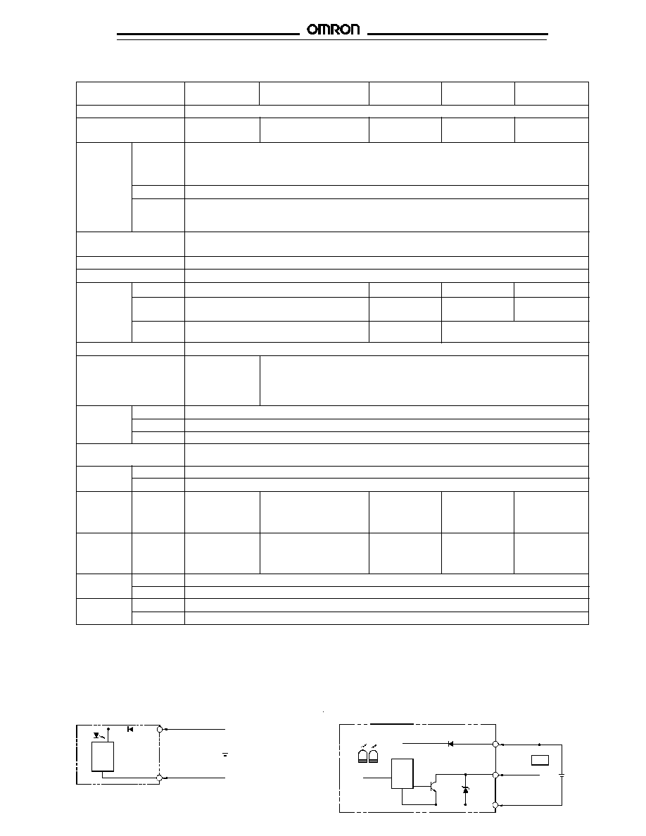
OUTPUT CIRCUIT DIAGRAMS
NPN Cable Type
Through-beam emitter E3S-AT11, E3S-AT61
Through-beam receiver E3S-AT11, E3S-AT61
Retroreflective E3S-AR11, E3S-AR61
Diffuse reflective E3S-AD11, E3S-AD12, E3S-AD13, E3S-AD61,
E3S-AD62, E3S-AD63
Light
(Red)
Stability
(Green)
Main
circuit
Z
D
Black (Blue)
100 mA
max.
White (Black) (relay)
Load
10 to 30
VDC
Red (Brown)
Main
circuit
Black (Blue)
10 to 30
VDC
Red (Brown)
SPECIFICATIONS (continued)
Ambient
temperature
NOTE: IEC colors are shown in parentheses.
4
E3S-A
E3S-A
NPN Cable Type with Self-Diagnostic Functions
Through-beam emitter E3S-AT21, E3S-AT71
Through-beam receiver E3S-AT21, E3S-AT71
Diffuse reflective E3S-AD21, E3S-AD22, E3S-AD71, E3S-AD72
10 to 30 VDC
Main
circuit
Grey (Pink)
Black (Blue)
0 V
Check
input
Red (Brown)
Light
(Red)
Stability
(Green)
Main
circuit
100 mA max.
50 mA max.
Load
(relay)
Black (Blue)
Self-diagnostic
output
(Orange)
White (Black)
Load
(relay)
10 to 30
VDC
Control
output
Z
D
Z
D
Red (Brown)
NPN Cable Type with Self-Diagnostic Functions
Retroreflective E3S-AR21, E3S-AR71
NPN Cable Type with Alarm Output
Diffuse reflective E3S-AD23, E3S-AD73
Main
circuit
Red (Brown)
Black (Blue)
10 to 30
VDC
Z
D
Light
(Red)
Stability
(Green)
Main
circuit
Red (Brown)
White (Black)
Control output
10 to 30
VDC
100 mA
max.
Load
Black (Blue) (relay)
Light
(Red)
Stability
(Green)
Main
circuit
100 mA max.
50 mA max.
Black (Blue)
(Orange)
White (Black)
10 to 30
VDC
Control
output
Z
D
Z
D
Red (Brown)
Alarm output
Load
(relay)
Load
(relay)
Z
D
Z
D
10 to 30
VDC
Orange
Check input
Black (Blue)
Self-diagnostic
output
50 mA
max.
12K
Light
(Red)
Stability
(Green)
Main
circuit
Red (Brown)
Load
(relay)
Load
(relay)
Control
output
White (Black)
Gray
(Pink)
100 mA max.
NOTE: IEC colors are shown in parentheses.
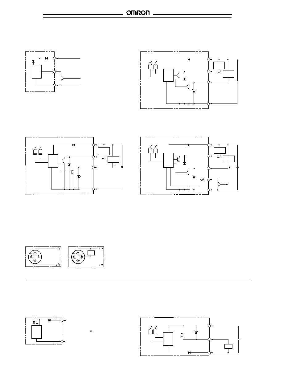
PNP Cable Type
Through-beam emitter E3S-AT31, E3S-AT81
Through-beam receiver E3S-AT31, E3S-AT81
Retroreflective E3S-AR31, E3S-AR81
Diffuse reflective E3S-AD31, E3S-AD32, E3S-AD33,
E3S-AD81, E3S-AD82, E3S-AD83
NPN Connector Type
Through-beam emitter
E3S-AT16, E3S-AT66
Through-beam receiver
E3S-AT16, E3S-AT66
Retroreflective E3S-AR16, E3S-AR66
Diffuse reflective E3S-AD16,
E3S-AD17, E3S-AD18, E3S-AD66,
E3S-AD67, E3S-AD68
Load
Output
(relay)

5
E3S-A
E3S-A
PNP Cable Type with Self-Diagnostic Functions
Through-beam emitter E3S-AT41, E3S-AT91
Through-beam receiver E3S-AT41, E3S-AT91
Diffuse reflective E3S-AD41, E3S-AD42, E3S-AD91, E3S-AD92
Main
circuit
Z
D
Z
D
100 mA max.
Red (Brown)
Self-diagnostic
output
Load
(relay)
Black (Blue)
50 mA max. Orange
Load
(relay)
White (Black)
Control
output
Stability
(Green)
Light
(Red)
10 to 30
VDC
Main
circuit
10 to 30 VDC
Check input
Black (Blue)
Gray (Pink)
0 V
Red (Brown)
PNP Cable Type with Alarm Output
Diffuse reflective E3S-AD43, E3S-AD93
Retroreflective E3S-AR41, E3S-AR91
Main
circuit
Z
D
Z
D
100 mA max.
Red (Brown)
Alarm
output
Load
(relay)
Black (Blue)
Orange (White)
Load
(relay)
White (Black)
Control
output
Light
(Red)
10 to 30
VDC
Main
circuit
Z
D
100 mA max.
Z
D
50 mA
max.
4.4K
Red (Brown)
Orange
Control output
Load
(relay)
Load
(relay)
Black (Blue)
Check
input
Self-
diagnostic
output
Gray (Pink)
White (Black)
Light
(Red)
Stability
(Green)
10 to 30
VDC
50 mA
max.
Stability
(Green)
PNP Connector Type
Through-beam emitter
E3S-AT36, E3S-AT86
Through-beam receiver
E3S-AT36, E3S-AT86
Retroreflective E3S-AR36, E3S-AR86
Diffuse reflective E3S-AD36,
E3S-AD37, E3S-AD38, E3S-AD86,
E3S-AD87, E3S-AD88,
(relay)
Output
Load
NOTE: IEC colors are shown in parentheses.
6
E3S-A
E3S-A
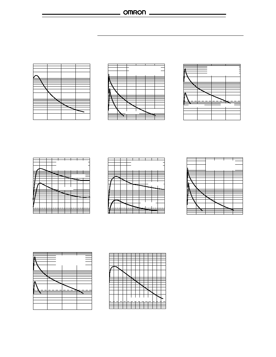
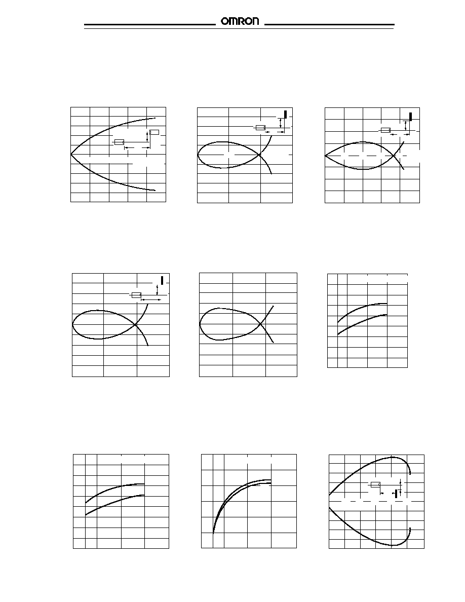
Engineering Data
s
EXCESS GAIN RATIO
Excess Gain vs. Set Distance
(Typical) E3S-AT
u
1
E3S-AD
u
1, -AD
u
2 (Detection of
White Paper)
E3S-AD
u
1, -AD
u
2 (Detection of
Black Paper)
Excess gain ratio
0
3
5
7
10
Distance (m)
Excess gain ratio
Distance (cm)
0
20
40
60
80
100
120
Excess gain ratio
Distance (cm)
0
20
40
60
80
Sensing object: black
(E3S-AD
s
s
2: 20 x 20 cm
E3S-AD
s
s
1: 10 x 10 cm)
E3S-AD
s
s
2
100
50
30
10
5
3
1
2.5
0.3
0.1
500
300
100
50
30
10
5
3
1
Sensing object: white
(E3S-AD
s
s
2: 20 x 20 cm
E3S-AD
s
s
1: 10 x 10 cm)
E3S-AD
s
s
2
E3S-AD
s
s
1
500
300
100
50
30
10
5
3
1
0.5
E3S-AD
s
s
1
E3S-AD
u
1, -AD
u
2 (White Paper within
Short Distance)
E3S-AD
u
1, -AD
u
2 (Black Paper within
Short Distance)
Sensing object: white
(E3S-AD
s
s
2: 20 x 20 cm
E3S-AD
s
s
1: 10 x 10 cm)
500
200
100
50
20
10
5
2
1
Sensing object: white
(E3S-AD
s
s
2: 20 x 20 cm
E3S-AD
s
s
1: 10 x 10 cm)
500
200
100
50
20
10
5
2
1
Excess gain ratio
0
1
2
3
4
5
6
7
8
9
E3S-AD
s
s
2
E3S-AD
s
s
1
Distance (cm)
Excess gain ratio
0
1
2
3
4
5
6
7
8
9
Distance (cm)
E3S-AD
s
s
2
E3S-AD
s
s
1
E3S-AD
s
s
3, -AD
s
s
8
(Detection of White Paper)
6
5
4
3
2
1
0
Sensing object: white
(E3S-AD
s
s
3/E3S-
AD
s
s
8: 10 x 10 cm)
Excess gain ratio
Distance X (mm)
50
100
150
200
E3S-AR
u
1 (With Reflector: E39-R1)
20
40
60
80
100
Sensing object: black
(E3S-AD
s
s
3/E3S-
AD
s
s
8: 10 x 10 cm)
6
5
4
3
2
1
0
Excess gain ratio
Distance X (mm)
E3S-AD
s
s
3, -AD
s
s
8
(Detection of Black Paper)
100
50
30
10
5
3
1
Excess gain ratio
Distance (m)
0 0.2 0.4 0.6 0.8 1 1.2 1.4 1.6 1.8 2 2.2 2.4 2.6
Operating level
7
E3S-A
E3S-A
Operating Range (Typical)
E3S-AD
u
1
s
OPERATING RANGE
Parallel Operating Range (Typical)
E3S-AT
u
1
E3S-AD
u
2
Distance X (m)
2
4
6
8
Y
50
40
30
20
10
0
10
20
30
40
50
Parallel operating range Y (cm)
X
Operating position Y (mm)
10
8
6
4
2
0
2
4
6
8
10
X
Y
Distance
X (cm)
10
20
4
3
2
1
0
1
2
3
4
Operating position Y (mm)
20
40
60
80
Distance
X (cm)
Y
X
s
OPERATING RANGE (typical)
s
SENSING DISTANCE VS.
OBJECT SIZE
E3S-AD
s
s
3, E3S-AD
s
s
8
E3S-AD
s
s
3, E3S-AD
s
s
8 (Left and Right)
Operating position Y (mm)
60
40
20
0
-20
-40
-60
X
Y
0
20
40
60
80
100 120
140 160
Distance X (mm)
Operating position Y (mm)
60
40
20
0
-20
-40
-60
Y
X
0
20
40
60
80
100 120
140 160
Distance X (mm)
0
5
10
15
20
25
30
35
Sensing object: white
OFF
ON
Sensing distance (mm)
200
180
160
140
120
100
Area of object (cm)
s
SENSING DISTANCE VS. OBJECT SIZE
s
REFLECTOR PARALLEL
MOVEMENT
E3S-AD
u
1
E3S-AD
u
2
(Typical) E3S-AR
u
1
38
36
34
32
30
28
26
24
22
20
Sensing distance (cm)
0 5x5 10x10 20x20 30x30
OFF
ON
Sensing object: white
Sensing distance (cm)
20
10
00
90
80
70
60
0 5x5 10x10 20x20 30x30
Size of object (cm)
Size of object (cm)
OFF
Sensing object: white
ON
10
8
6
4
2
0
2
4
6
8
10
Parallel operating range Y (cm)
X
Y
0.5
1.0
1.5
2.0
2.5
Distance X (m)
E3S-AD
s
s
3, E3S-AD
s
s
8 (Up and Down)
E3S-A
E3S-A
8
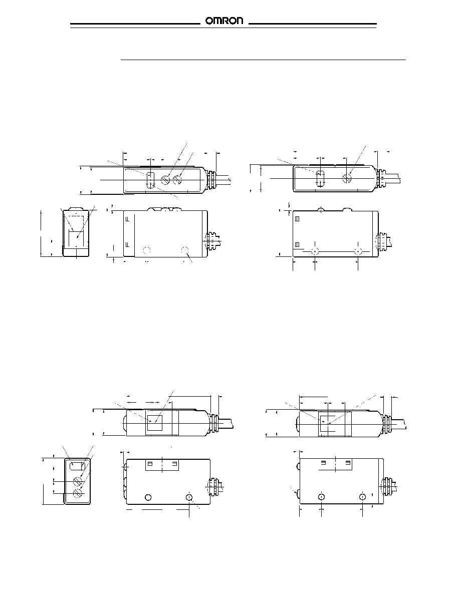
Dimensions
Unit: mm (inch)
s
SENSORS
E3S-AD11, E3S-AD12, E3S-AD13, E3S-AD31, E3S-AD32,
E3S-AD33 (see note 1), E3S-AD21, E3S-AD22,
E3S-AD23, E3S-AD41, E3S-AD42, E3S-AD43
Receiver: E3S-AT11, E3S-AT31 (see note 2)
Emitter: E3S-AT11, E3S-AT31 (see note 3)
E3S-AT21, E3S-AT41
E3S-AT21, E3S-AT41
M3 holes (typ.)
Lens 7 x 7
Optical axis
7
4
12
12.5
Turbo switch
1.3
12.9
21
8
1.3
12
40 (1.57)
12.9
5.5
20
10.5
20
10.5
4
40 (1.57)
Sensitivity adjuster (white)
Time adjuster (black)
12.4
(0.49)
12.4
(0.49)
22.3
(0.88)
22.3
(0.88)
2.5
Light indicator (red)
Stability indicator (green)
Light indicator (red)
Stability indicator
(green)
Optical axis
4
13.5
12
12.4
Time adjuster
(Turbo switch)
(black)
Light indicator
(red)
Sensitivity
adjuster
(white)
21
3.6
7
5.5
4
12.4
12
1.3
1.3
20
10.5
20
10.5
8.3
8.3
40
M3 holes (typ.)
Turbo
switch
2.5
Lens 7 x 7
Lens 7 x 7
Optical axis
13.5
40
NOTES: 1. No time adjuster/turbo included on models E3S-AD61, E3S-AD62, E3S-AD81and E3S-AD82.
2. No time adjuster included on models E3S-AT61 and E3S-AT81.
3. No turbo switch included on models E3S-AT61 and E3S-AT81.
E3S-AD61, E3S-AD62, E3S-AD63, E3S-AD81, E3S-AD82,
E3S-AD83 (see note 1), E3S-AD71, E3S-AD72, E3S-AD73,
E3S-AD91, E3S-AD92, E3S-AD93
Receiver: E3S-AT61, E3S-AT81 (see note 2)
Emitter: E3S-AT61, E3S-AT81 (see note 3)
E3S-AT71, E3S-AT91
E3S-AT71, E3S-AT91
E3S-A
E3S-A
9
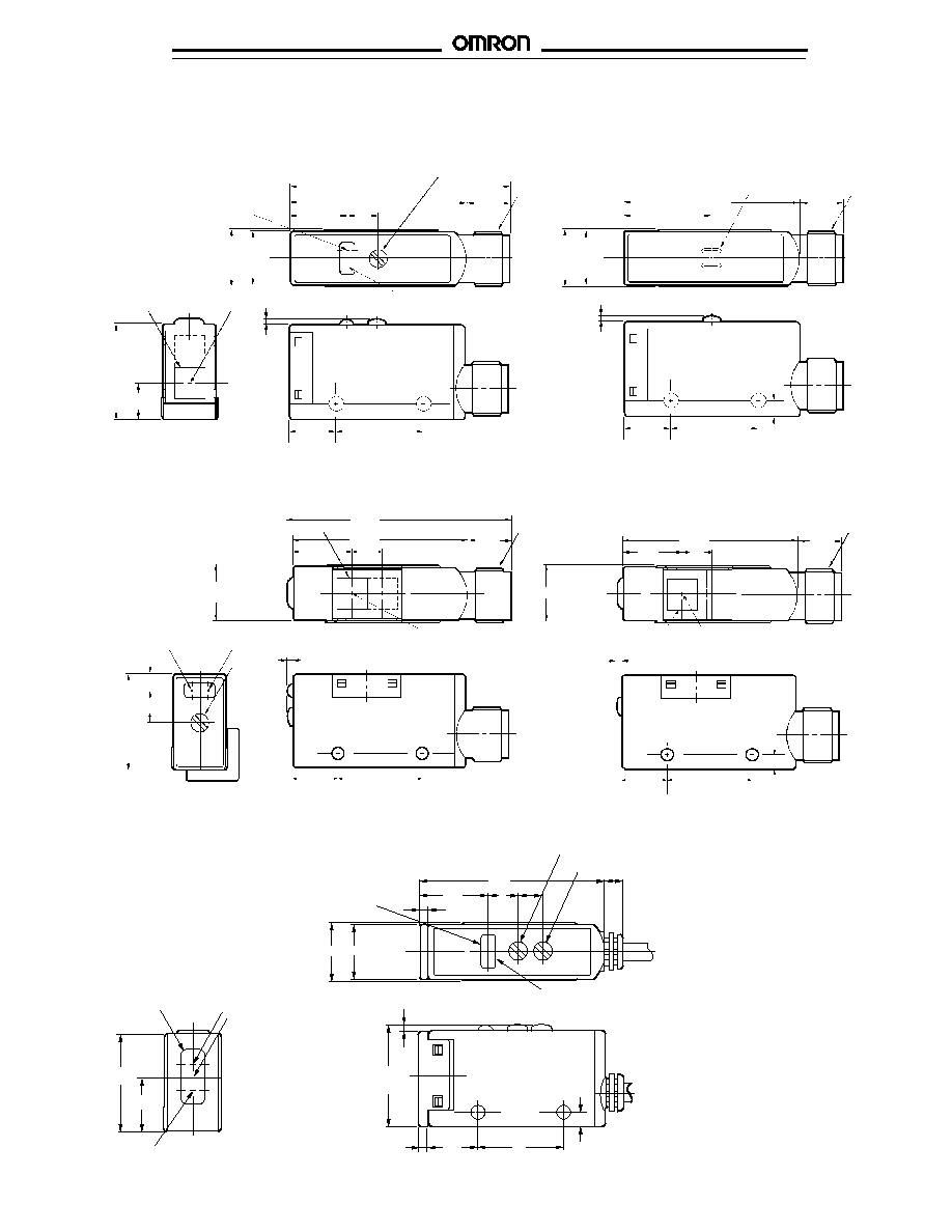
SENSORS (continued)
E3S-AD16, E3S-AD17, E3S-AD18, E3S-AD36, E3S-AD37, E3S-AD38
Receiver: E3S-AT16, E3S-AT36
Emitter: E3S-AT16, E3S-AT36
7
1.3
12
10
50 (1.97)
M12
connector
20
10.5
Optical axis
Lens 7 x 7
21
8
12.9
40
Sensitivity adjuster
(white)
(receiver only)
12.4
(0.49)
Light indicator (red)
Stability indicator (green)
12
12.4
Light indicator (red)
10
M12
connector
1.3
20
40
17.8
2.5
10.5
M12
connector
Lens 7 x 7
51.3
(2.02)
10
40
13.5
8.3
E3S-AD66, E3S-AD67, E3S-AD68, E3S-AD86, E3S-AD87, E3S-AD88
Receiver: E3S-AT66, E3S-AT86
Emitter: E3S-AT66, E3S-AT86
21
(0.83)
7
1.3
Light indicator
(red)
Stability indicator
(green)
3.6
Sensitivity
adjuster
(white)
20
10.5
12
(0.47)
Optical axis
M12
connector
12
13.5
8.3
10
40
1.3
20
10.5
2.5
Lens 7 x 7
Optical axis
2.3
5.5
42.3
7
15.2
12
1.3
20
10.5
2.3
21.3
(0.89)
21
11.5
Emitter
Lens 7 x 14
Receiver
Optical axis
12.4
9
Turn to adjust the OFF-delay time:
push to switch turbo function on.
OFF-delay time adjuster/turbo
switch (black)
Sensitivity
adjuster
(white)
2.5
Light indicator (red)
Stability indicator (green)
E3S-AR11, E3S-AR31 (see note)
E3S-AR21, E3S-AR41
NOTE: No time adjuster/turbo included on models E3S-AR11 and E3S-AR31.
E3S-A
E3S-A
10
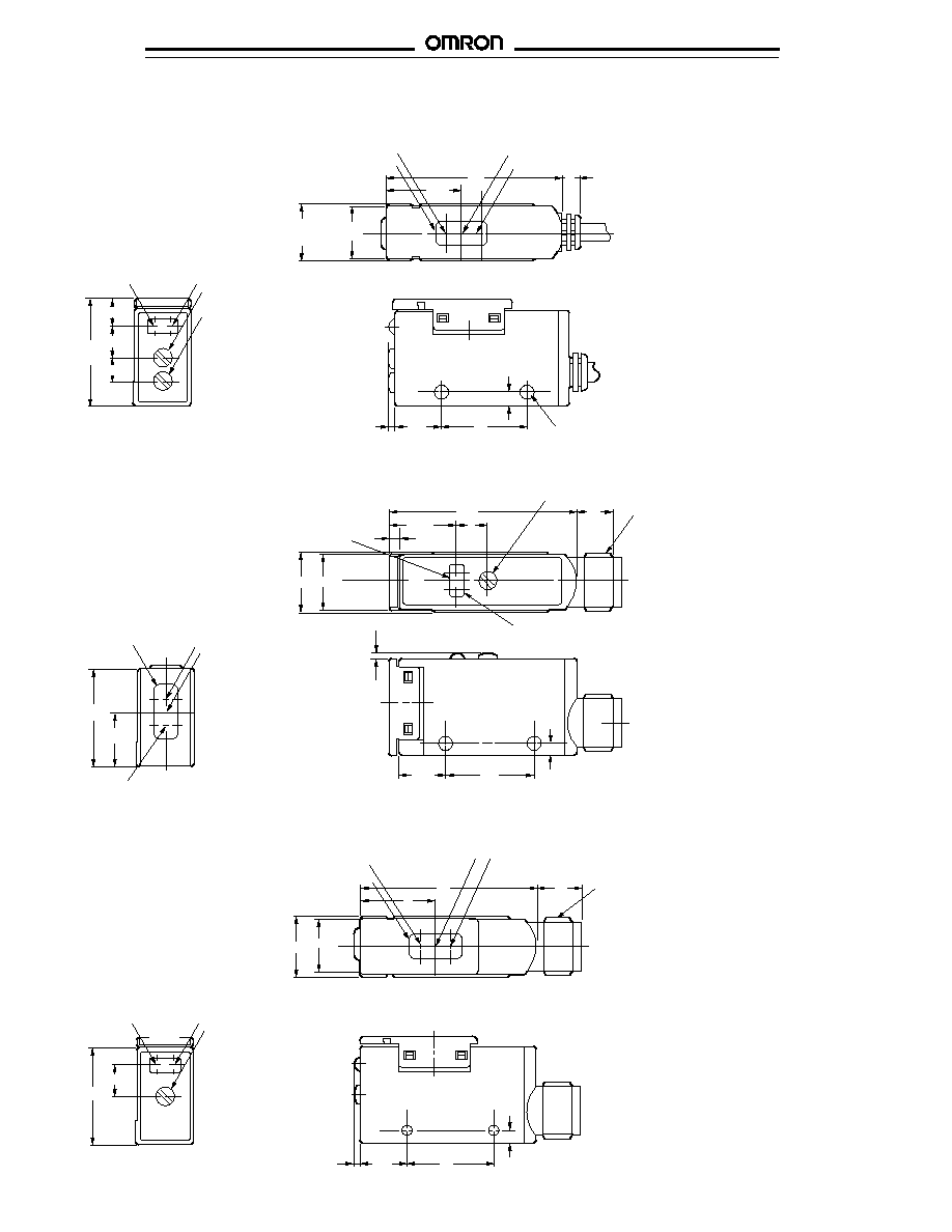
SENSORS (continued)
E3S-AR61, E3S-AR81
E3S-AR71, E3S-AR91
Receiver
Lens 7 x 14
Optical axis
Emitter
40
8.3
4
13.5
12.4
(0.49)
12
12
10.5
Stability indicator
(green)
1.3
Light indicator (red)
5.9
23.3
(0.92)
5.5
7
M3 holes (typ.)
Sensitivity adjuster (white)
OFF-delay time
adjuster/turbo
switch (black)
Turn to adjust the
OFF-delay time:
push to switch
turbo function
20
2.5
E3S-AR16, E3S-AR36
Sensitivity adjuster (white)
42.3
7
12.4 12
1.3
Receiver
21
11.5
10
M12
connector
10.5
Optical axis
Lens 7 x 14
15.2
20
2.5
2.3
Light indicator (red)
Stability indicator (green)
Emitter
E3S-AR66, E3S-AR86
Sensitivity adjuster (white)
Stability
indicator
(green)
Light
indicator
(red)
7
21
Receiver
14.9
12
17
40
10
Optical axis
Emitter
3.6
10
M12
connector
Lens 7 x 14
2.5
20
1.3
10.5
E3S-A
E3S-A
11
s
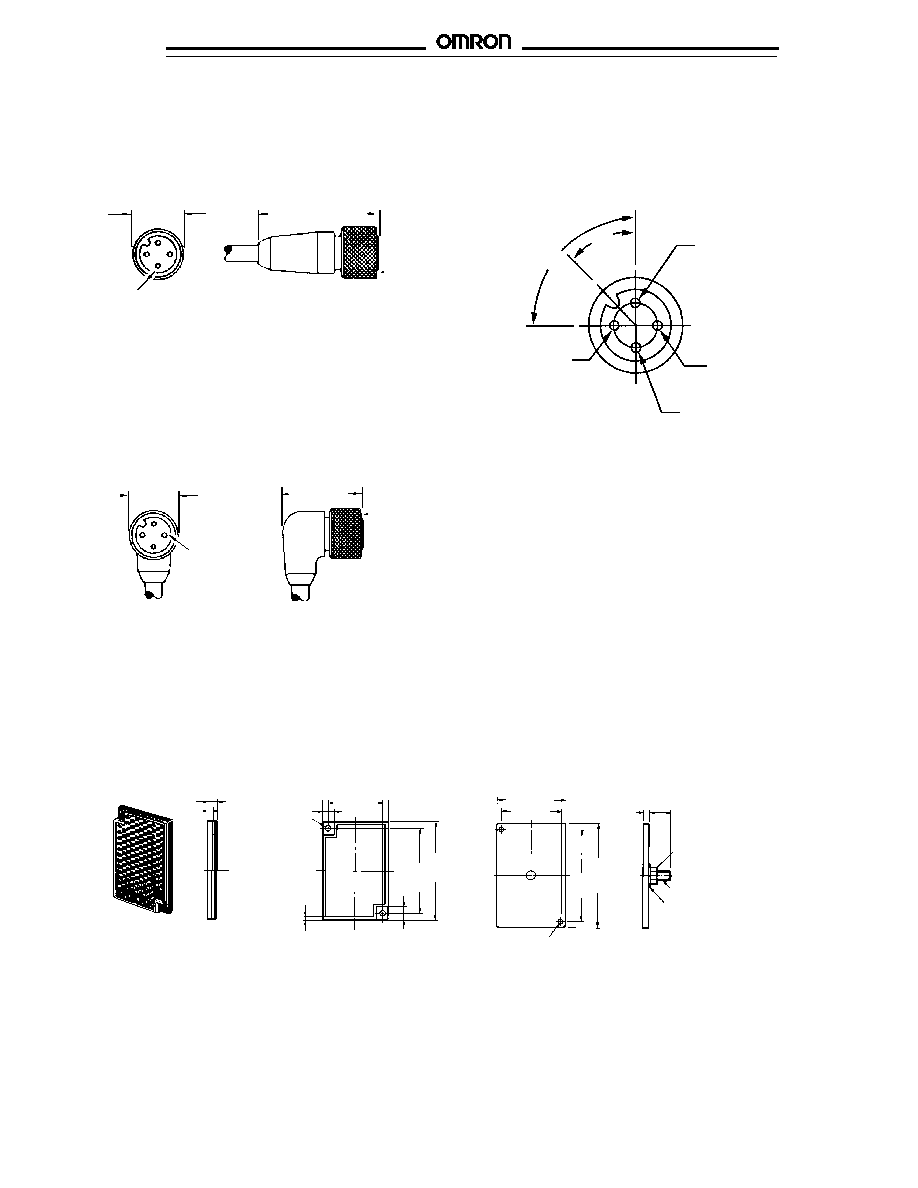
OPTIONAL CONNECTOR CORDSETS
Cordsets consist of a female connector and 3-conductor, 22 AWG, PVC jacketed cable rated for 300 V, 90
�
C. The cable may be
extended to a maximum of 200 m (656 ft).
Silver-plated
copper contacts
14.67
(0.57)
34.92
(1.32)
Aluminum
coupling nut
Straight Connector Cordsets Y96E-43SD
u
2 m (6.56 ft) length for Y96E-43SD2
5 m (16.40 ft) length for Y96E-43SD5
10 m (32.81 ft) length for Y96E-43SD10
Right Angle Connector Cordsets Y96E-43RD
u
2 m (6.56 ft) length for Y96E-43RD2
5 m (16.40 ft) length for Y96E-43RD5
10 m (32.81 ft) length for Y96E-43RD10
Face View, Female Connector
90
�
45
�
2. Output*
White
3. 0 V
Black (Blue)
1. +V
Red
(Brown)
4. Output
White (Black)
14.67
(0.57)
Silver-plated
copper contacts
Aluminum
coupling nut
26.5
(1.04)
NOTES:
*Not used on 3-wire models.
IEC colors are shown in parentheses.
E39-R1 Reflector
(included with E3S-AR
uu
)
s
CORNER CUBE REFLECTORS
7.5 (0.30)
2.7 (0.11)
7 (0.276)
1.6 (0.06)
34 (1.339)
52
(2.07)
52
(2.05)
59
(2.32)
Two M3
12
(0.47)
3.2 (0.13)
Nut (M5)
Spring washer (M5)
M5
E39-L7 Reflector Adapter
for E39-R1 Reflector
Two 3.5
(0.14)
dia.
8 (0.32)
59.9
(2.36)
39.3 (1.55)
34 (1.34)
E3S-A
E3S-A
12
s
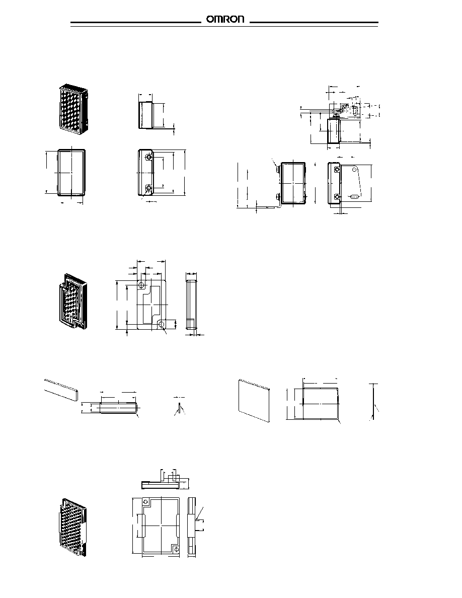
CORNER CUBE REFLECTORS (continued)
E39-R3 Optional Reflector
11
20
0.2
34.8
19.3
Two M3
1.2
25.4 34
38
Dimensions with E39-L54 Mounting Bracket (included)
41.8 25.4
�
0.1
10.1
1.2
Two M3
38
(1.50)
3.4
7
18.45
4.5
29
(1.14)
6
3.4
14
�
13.7
20
0.2
11
(0.43)
16
(0.63)
34
(1.33)
1.2
22.9
E39-R4 Optional Mini-reflector
13.7
4
2
9.7
�
0.1
4.9
4
1.4
Two, 2.2 dia.
2
19
�
0.1
23
E39-RSA Optional Adhesive-backed Reflector
35
33
10 8
Four 1R
Reflective
surface
Adhesive tape side
0.7
40
38
33
35
Four 1R
Reflective
surface
Adhesive
tape side
0.7
E39-RSB Optional Adhesive-backed Reflector
E39-R5 for E3S-A Sensors
s
OPTICAL AXIS CONFIRMATION REFLECTOR
25
59.9
11.2
7.9
9.7
7.5
9.7
15.9
11.6
11.7
40.9
Bracket clips to
the front of E3S-A
receiver

E3S-A
E3S-A
13
E39-S46 Slits
Kit for through-beam sensors contains 0.5 mm, 1 mm and
2 mm wide slits and mounting frame.
s
SLITS AND FILTERS
E39-E6 Mutual Interference Filter
E39-L60 Spacer
s
MOUNTING SPACER FOR CONNECTOR-TYPE SENSORS
11.6
A
6.8
2.1
9.7
13.6
or
11.1
21.4
A = Slit width
11.6
21.4
6.8
2.1
33
20
6.5
6.5
2.5
5
11.75
2.5
3.4 dia.
3.4 dia.
11.75
5
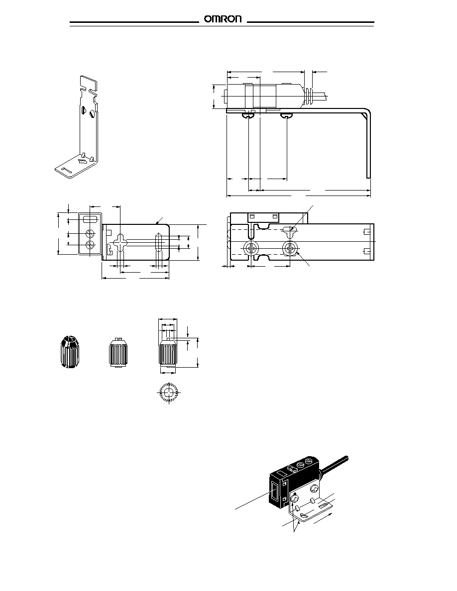
E39-L69 Mounting Bracket
s
MOUNTING BRACKETS (supplied with sensors)
E39-L70 Mounting Bracket
10.7
3.2 7.2
3.2
4.8
5
20
30
1.2
10.7
16.5
Two, M3 x 12
screws
1.2
20
3.1
3.6
7.2
10.7
16.5
41.7
10.7
20
7.2
Four
mounting
holes
Two, M3 x 12
screws
E3S-A
E3S-A
14
s
E39-L59 OPTIONAL VERTICAL MOUNTING BRACKET
40
17
12
10
20
10.5
1.3
18
6.2
3.2
3.2
20
34.5
3.2
21
3.6
15.7
7
5.5
s
E39-G2 SENSITIVITY ADJUSTER KNOB
0.8
1
12.6
7 dia.
8 dia.
s
MOUNTING BRACKET NOTCH
Each mounting bracket slot has a notch to provide a center position
for aligning the sensor parallel to the bracket. This ensures that the
beam is aligned with the mounting surface.
E3S-A
Mounting bracket (E39-L59)
Two mounting holes
Two, M3 x 12 screws
Optical axis
6.5
74.3
57.3
20
10.5
Base of mounting
bracket
Bracket can move
in this direction
Optical axis
lock hole (M3)
Mounting
direction
E3S-A
E3S-A
15
Operation
Photoelectric sensor
Sensing object
Photoelectric sensor
Sensing object
Min
Max
Min
Max
Min
Max
A
B
B
A
OFF
ON
OFF
OFF
ON
OFF
LIGHT
(red)
STABILITY
(green)
LIGHT
(red)
STABILITY
(green)
LIGHT
(red)
STABILITY
(green)
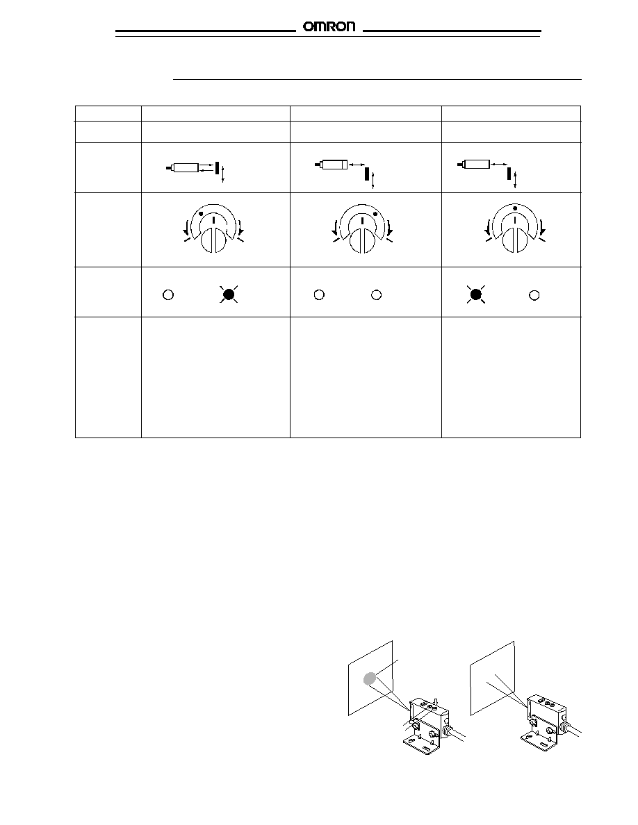
Place target at the desired
sensing distance. Set sensitivity
adjuster to the minimum scale
position, and gradually increase
sensitivity by turning the sensitiv-
ity adjuster clockwise until the
Light Incident indicator (red LED)
turns ON. Position A designates
the point at which the LED has
turned ON.
Remove the target. Starting from
the maximum scale position,
gradually decrease sensitivity by
turning the sensitivity adjuster
counterclockwise until the Light
Incident indicator (red LED) turns
OFF. Position B designates the
point at which the LED has turned
OFF.
Set the sensitivity indicator to the
position between Positions A and
B (in some cases, Positions A
and B are opposite of the above
example). The photoelectric
sensor will then work normally if
the stability indicator (green) is lit
with and without the target. If it
is not lit, stable operation cannot
be expected, in which case a
different detection method should
be applied.
Unlike conventional photoelectric sensors, the variation in the sensitivity of E3S photoelectric sensors is minimal. This means the
sensitivity can be adjusted on only a single photoelectric sensor, and then the adjusters on the other photoelectric sensors can be set
to the same scale position. There is no need to adjust the sensitivity of each photoelectric sensor individually.
Photoelectric sensor
Sensing object
Steps
Step 1
Step 2
Step 3
Function
Determine Position A
Determine Position B
Adjust to optimum setting
Sensing
Condition
Sensitivity
adjuster
Indicators
Procedure
s
SENSITIVITY ADJUSTMENT
s
TIMER AND TURBO SWITCH
E3S Sensors equipped with the self-diagnostic feature incorpo-
rates an OFF-delay timer that can be adjusted within range of 0 to
100 ms.
The emitter of the through-beam sensor with the self-diagnostic
feature incorporates a turbo switch. When this switch is on, the
intensity of the red LED light source can be increased to make a
brighter spot. The OFF-delay time adjuster of the retroreflective
and the 20-cm diffuse reflective sensor is used as a turbo switch.
When the adjuster is pressed, it functions as a turbo switch to
automatically increase the power of the light source to create a
brighter light spot. Do not press the adjuster when turning it.
Turbo Function (Turbo Switch)
With the turbo function switched ON, the light spot is visible even
at a distance of 20 cm (7.87 in), making it easy to check the sensing
position and the angle of the optical axis.
1. After using the turbo function, readjust the OFF-delay time
that had been set, since the OFF-delay time could have
been changed when the turbo switch (which is on the OFF-
delay time adjuster) was pressed.
2. Press the OFF-delay time adjuster to switch ON the turbo
function with a maximum force of 1 kg and within a maximum
period of 3 minutes. (The photoelectric sensor, however, will
not malfunction even if the turbo function is switched on for
more than 3 minutes.)
The turbo function is effective with the turbo switch pressed, and
the function is reset automatically when released.
Normal Operating Condition
Sensitivity adjuster
With Turbo Switch ON
Visible spot
PUSH
The OFF-delay
time adjuster is
used as a turbo
switch (black)
E3S-A
E3S-A
16
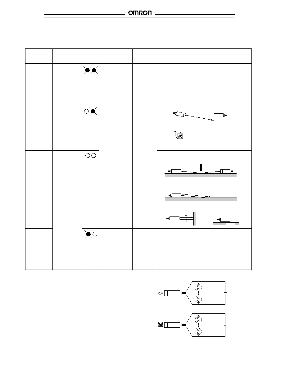
Self-Diagnostic Function
Self-
diagnostic
function
--
The self-
diagnostic
alarm output
alerts the
user to this
state if it
continues for
0.3 s.
--
Green Indicator
Stable operating
state with incident
light: Stable
operation is
expected in the
rated temperature
range with the
green indicator
ON.
Conditional
operating state
with incident light:
Stable operation is
expected if the
temperature
fluctuation is within
�
10% of the
primary
temperature.
Stable operating
state with no
incident light:
Stable operation is
expected in the
rated temperature
range with the
green indicator
ON.
Amount of
incident light
1.2 or more
1.0 to 1.2
0.8 to 1.0
0.8 or less
Indicator
Green Red
Green Red
Green Red
Green Red
With this function, the E3S-A sensor checks changes in environmental conditions (especially a change in the ambient temperature) and
self-diagnoses the resistance against the changes. The result is shown by the indicators or an output signal.
Incident light
indicator (red)
With light
incident (red
indicator: ON)
Without light
incident (red
indicator: OFF)
Sensing object
Self-diagnostic example
--
The optical axis misaligned by vibration.
Light decreased by dust.
With light leakage (through-beam and retroreflective
sensors)
Light reflected from the floor or the background (diffuse
reflective sensors)
--
With the influence of
external noise
Sensing
object
Noise
s
EXTERNAL DIAGNOSTIC INPUT FUNCTION
To switch the emission off, short-circuit the gray (pink) and the
black (blue) cords of the emitter of the E3S-AT
u
or the
E3S-AR
u
with the NPN output feature. For the E3S-AR
u
with
the PNP output feature, short-circuit the gray (pink) and the red
(brown) cords.
Light emission
Red (Brown) + V
No emission
Red (Brown) + V
Black (Blue) 0 V
ON
(with PNP output)
ON
(with NPN output)
Black (Blue) 0 V
OFF
(with PNP output)
Gray (External-
diagnostic input)
OFF
(with NPN output)
Gray (Pink)
(External-
diagnostic input)
NOTE: IEC colors are shown in parentheses.
Dust
E3S-A
E3S-A
17
Aduster cap
s
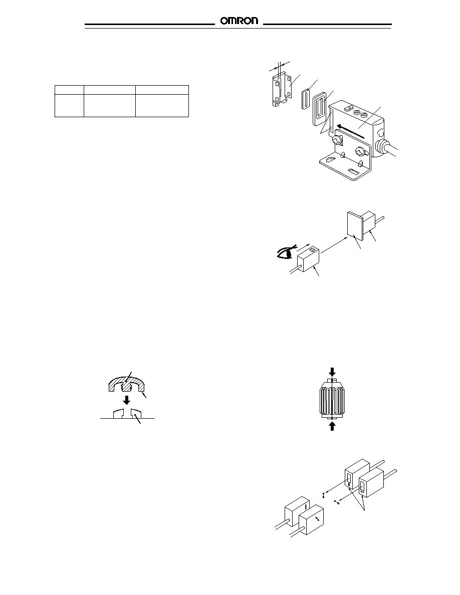
SLITS FOR THROUGH-BEAM SENSORS
E39-S46 Slit Set
Using slits allows smaller objects to be detected and reduces
the sensing distance.
Use the rubber attachment with the metal cover if a slit width of
2 mm is required. Insert the 0.5- or 1-mm slit between the metal
cover and rubber attachment if a slit width of 0.5 or 1 mm is
desired. These slits fit into the rubber attachment.
NOTE: Apply the slit to the lens of the photoelectric sensor
marked with an arrow indicating the position of the
optical axis (apply it to the bottom lens of horizontal
sensors and the top lens of vertical sensors).
Slit width Sensing distance
Min. object size
0.5 mm
0.5 m (1.64 ft)
0.5 mm (0.02 in)
1 mm
1.1 m (3.61 ft)
1 mm (0.04 in)
2 mm
2.4 m (8.20 ft)
2 mm (0.08 in)
2 mm
Metal cover
Slit (0.5 mm or 1 mm)
Rubber attachment
Arrow indicating
position
of optical axis
Notches to hold cover
E3S-A
s
OPTICAL AXIS CONFIRMATION REFLECTOR E39-R5
Use this attachment when the set distance is long and
adjustment is mechanically difficult with a sensing object.
Attach the reflector to the receiver (refer to the figure).
Look at the reflector from right behind the emitter. The
reflector should be bright with red light when the optical
beam strikes the reflector. If the emitter has a turbo
function, the reflector looks brighter with the function
switched on.
When the reflector is removed, the light beam strikes the
receiver.
Eye
Emitter
Receiver
E39-R5
s
ADJUSTER CAP AND OPTIONAL E39-G2 SENSITIVITY ADJUSTER KNOB
In order to prevent the sensitivity or OFF-delay time that
has been set from changing accidentally, cover the
adjusters with the adjuster cap (enclosed).
To temporarily use the knob to adjust the sensitivity of the
photoelectric sensor, insert side A into the shaft of the
sensitivity adjuster. To snap the adjuster onto the sensor,
push side B onto the sensitivity knob.
Press the adjuster cap until
this face touches the name
plate on the sensor.
Aduster
(B)
(A)
s
E39-E6 MUTUAL INTERFERENCE FILTER
A set of 4 filters are sold together for two through-beam
models (for 2 each of emitters and receivers).
The arrow printed on the cover indicates the direction of
polarization. By attaching the filters opposite to each other
in polarization to the emitters and the receivers (refer to
the figure) in rows, mutual interference can be prevented
(in any case, the filter attached to an emitter and to the
corresponding receiver must be the same in direction of
polarization or the photoelectric sensor will not function).
Optical axis
confirmation
reflector
Emitter
Be aware of the direction of
polarization.
Receiver
Adjuster Cap (Supplied with each sensor)
E39-G2 Adjuster Knob

E3S-A
E3S-A
18
NOTE: DIMENSIONS ARE IN MILLIMETERS. To convert millimeters to inches divide by 25.4.
Omron Europe B.V. EMA-ISD, tel:+31 23 5681390, fax:+31 23 5681397, http://www.eu.omron.com/ema
Cat. No. CEDSAX2 3/97 Specifications subject to change without notice. Printed in the U.S.A.