 | –≠–ª–µ–∫—Ç—Ä–æ–Ω–Ω—ã–π –∫–æ–º–ø–æ–Ω–µ–Ω—Ç: E4B-TjS | –°–∫–∞—á–∞—Ç—å:  PDF PDF  ZIP ZIP |
Document Outline
- First Page
- Ordering Information
- Specifications
- Operation
- Engineering Data
- Installation
- Precautions
- Contacting Omron

R
2
Ultrasonic Sensor With Zone Sensing
E4B
Through-beam, Reflective and
Zone Models
H
1 m through-beam for long range
applications
H
Narrow beam angle of 8∞ detects
objects as small as 2 x 2 cm
H
Zone models detect objects smoothly
while suppressing interference from
background objects
H
200 kHz provides high immunity from
environmental noise
H
User-selectable normally open and
normally closed operation
Ordering Information
Supply voltage
Sensing type
Sensing distance
Cable length
Part number
Supply voltage
Sensing type
Sensing distance
Cable length
NPN output
PNP output
12 to 24 VDC
Through-beam
1 m
2 m
E4B-T1E4 2M
E4B-T1F4 2M
12 to 24 VDC
Through beam
1 m
5 m
E4B-T1E4 5M
E4B-T1F4 5M
50 cm
2 m
E4B-TS50E4 2M
E4B-TS50F4 2M
50 cm
5 m
E4B-TS50E4 5M
E4B-TS50F4 5M
Zone setting
20 to 70 cm
2 m
E4B-RS70E4 2M
E4B-RS70F4 2M
Zone setting
20 to 70 cm
5 m
E4B-RS70E4 5M
E4B-RS70F4 5M
Distance setting
20 to 70 cm
2 m
E4B-LS70E4 2M
E4B-LS70F4 2M
Distance setting
20 to 70 cm
5 m
E4B-LS70E4 5M
E4B-LS70F4 5M
5 to 20 cm
2 m
E4B-LS20E4 2M
E4B-LS20F4 2M
5 to 20 cm
5 m
E4B-LS20E4 5M
E4B-LS20F4 5M
E4B
E4B
3
J
SENSING TYPE
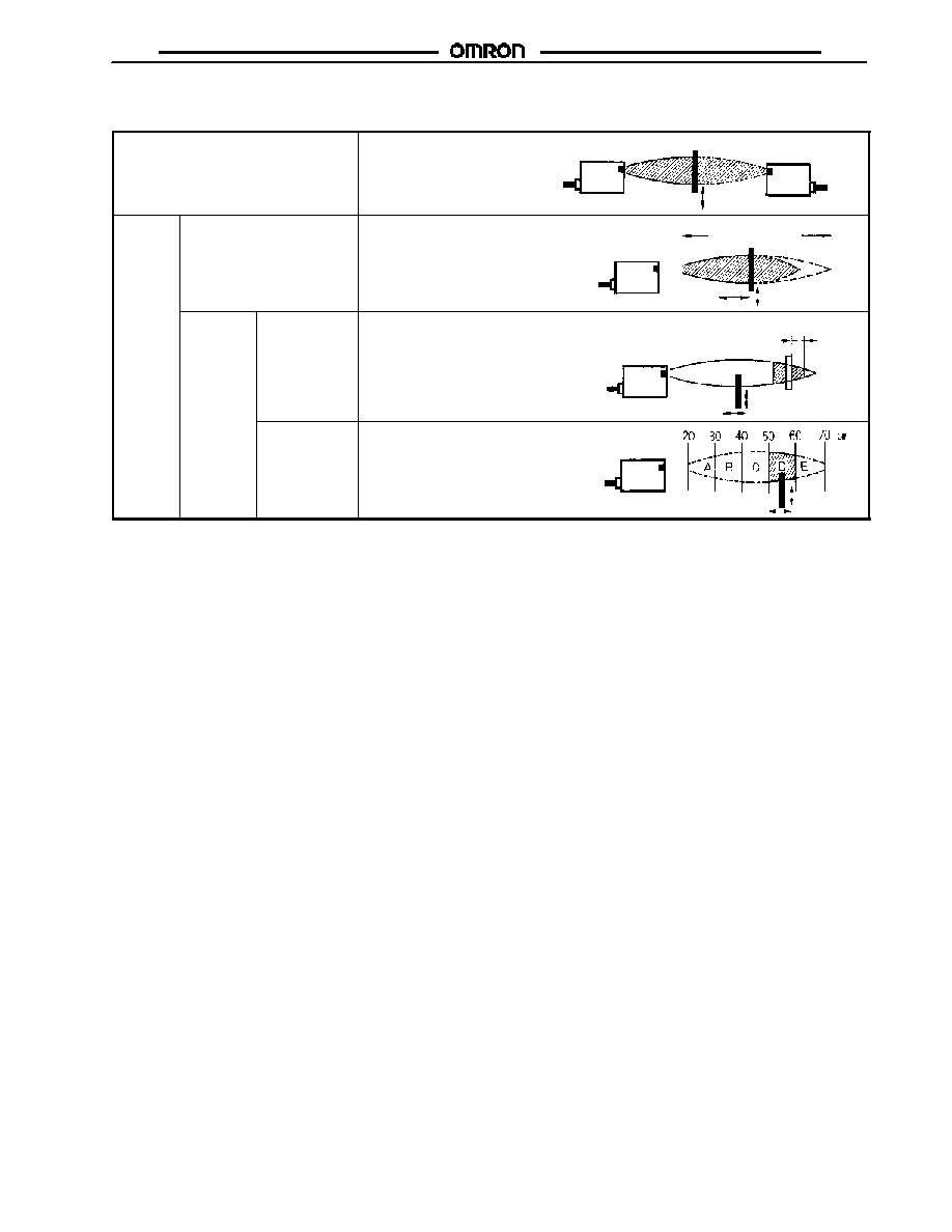
Through-beam
Detects the attenuation or interrupted condition
of the ultrasonic beam caused by the object
passing between the Emitter and Receiver.
E4B-TjS Emitter
Sensing object
E4B-TjR Receiver
Reflective Setting distance
Detects only the beam reflected from the
object existing within the sensing distance
range set with the distance adjuster.
Unstable range
Distance adjustment
Sensing object
E4B-LSj
Setting
zone
Sensing
background
Detects the object with the interruption of the
normal beam reflected from the acoustically
reflective surface.
Sensing distance
adjustable range
Acoustically reflective
surface
Sensing
object
E4B-RS70
Sensing target
Detects only the beam reflected from the
object existing in the sensing range set with
the distance selector.
Unstable range
Sensing
object
E4B-RS70
Note: An object may be detected due to multiple reflection if the object is in the unstable range where the distance adjuster is ineffective,
in which case however, the detection of the object will not be stable. Therefore, do not attempt to use the E4B to detect an object
in the unstable range.

E4B
E4B
4
Specifications
J
RATINGS/CHARACTERISTICS
Part number
E4B-TS50E4
E4B-T1E4
E4B-LS20E4
E4B-LS70E4
E4B-RS70E4
Sensing method
Through-beam
Distance setting
Zone setting
Supply voltage
12 to 24 VDC ± 10% (10.8 to 26.4 VDC) with a max. ripple ±10% (p-p)
Current
consumption
12 VDC
Emitter: 155 mA
max.
Receiver: 30 mA
max.
Emitter: 70 mA
max.
Receiver: 30 mA
max.
100 mA max.
24 VDC
Emitter: 80 mA
max.
Receiver: 30 mA
max.
Emitter: 50 mA
max.
Receiver: 30 mA
max.
50 mA max.
Sensing distance
50 cm (19.69 in)
1 m (3.28 ft)
5 to 20 cm
(1.97 to 7.87 in)
20 to 60 cm
(20 to 70 cm)
(See Note 1.)
(7.87 in to
23.62 in)
20 to 60 cm
(20 to 70 cm)
(See Note 1.) (in
10-cm divisions)
(7.87 to 23.62 in)
Standard sensing object
10 x 10 cm flat plate
4 x 4 cm flat plate
Differential travel
--
20% max. of sensing distance
3 cm max.
Directional angle (See Note 2.)
±8∞ max.
Ultrasonic oscillation frequency
200 kHz
Switching frequency (See Note 3.)
50 Hz
10 Hz
50 Hz
20 Hz
Response time
10 ms
50 ms
10 ms
25 ms
Operating mode
N.O. or N.C. selectable
Control output
NPN
100 mA at 30 VDC (with a residual voltage of 1.5 V max.) and an output resistance of 4.7 k
Control output
PNP
100 mA at 30 VDC (with a residual voltage of 1.5 V max.) and an output resistance of 4.7 k
Residual voltage
1.5 V max. under a load current of 100 mA
Indicators
SENSING indicator (red LED) and STABILITY indicator (green LED)
Ultrasonic speed compensation
No
Yes
Ambient operating temperature
--10∞C to 55∞C (14∞F to 131∞F)
Relative humidity
35% to 95%
Temperature influence
±10% max. of sensing distance at 20∞C (68∞F) in the temperature range of --10∞C and 55∞C
(14∞F to 131∞F)
Voltage influence
±5% max. of sensing distance at a voltage between 90% and 110% of the rated power supply
voltage
Insulation resistance
20 M min. at 500 VDC between current carry parts and case
Dielectric strength
1,000 V (50/60 Hz) for 1 min between current carry parts and case
Vibration resistance
10 to 55 Hz, 1.5-mm double amplitude for 2 hours each in X, Y, and Z axes
Shock resistance
500 m/s
2
(approx. 50G) 3 times each in X, Y, and Z axes
Enclosure rating
IEC IP66 (water resistant)
Approvals
UL, cUL
Recognized, File No. E41515 when used with a Class 2 power source
Weight (with 2-m-long cord and
Mounting Bracket)
Approx. 600 g (21 oz) with Emitter
and Receiver
Approx. 300 g (10.6 oz)
Note: 1. These are the available sensing distances at an ambient temperature range between 0∞C and 45∞C (32∞F to 113∞F)
2. Signal attenuation of --6 dB.
3. The switching frequencies are values obtained with the E4B used for detecting a rotating propeller-shaped disc as shown
below.
Space:Blade = 1:1
E4B
E4B
5
Operation
J
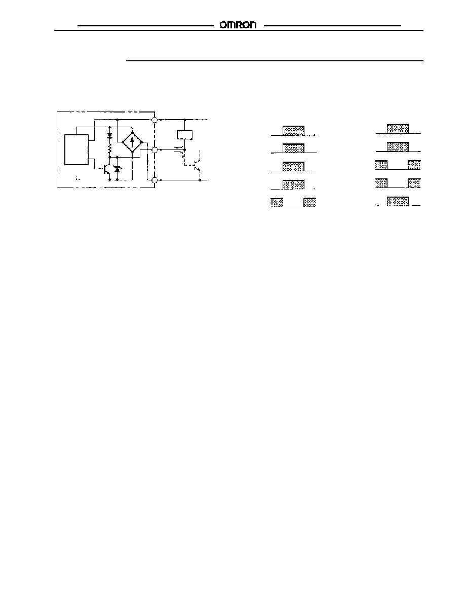
OUTPUT CIRCUITS
NPN Output DC
Main
circuit
Note: 1. 100 mA max. (load current)
2. Required when the transistor circuit is connected.
Signal received, output on
(Power supply polarity:
Brown: +; Blue: 0 V)
STABILITY
indicator (red)
Output
transistor
Load (relay)
Output voltage
(logic)
Signal not received, output on
(Power supply polarity:
Brown: 0 V: Blue: +)
Brown
Black
Blue
Signal received
Signal interrupted
ON
OFF
Operate
Release
(Brown Black)
(Blue Black)
STABILITY
indicator (red)
Output
transistor
Load (relay)
Output voltage
(logic)
Sound incident
Sound interrupted
ON
OFF
Operate
Release
(Brown Black)
(Blue Black)
Load
0 V
+ V
Note 1.
Note 2.
4.7k
W
PNP Output
(No Diagram Provided)
ON
OFF
ON
OFF
L
H
L
H

E4B
E4B
6
Engineering Data
J
OPERATING DISTANCE VS. SENSING OBJECT SIZE (TYPICAL)
E4B-TS50E4, E4B-T1E4
E4B-LS20E4
E4B-LS70E4, E4B-RS70E4
Sensing position
E4B-T1E4:
Sensitivity adjuster
set to Max.
E4B-TS50E4:
Sensitivity adjuster set to Max.
Sensitivity adjuster: Adjust with stable incident.
Sensing position X (cm) (from Receiver)
Sample: Round pipe
that is 10 cm long
min.
Sample: Round pipe
that is 10 cm long
min.
Sensing distance (cm)
Operating distance (cm)
E4B-LS20E4
E4B-LS70E4, E4B-RS70E4
J
OPERATING DISTANCE VS.
SENSING OBJECT ANGLE
(TYPICAL)
S
ens
i
n
g
d
i
s
t
anc
e
(
c
m
)
Sensing distance (cm)
55-dia. rod
30-dia. rod
S
ens
i
n
g
d
i
s
t
anc
e
(
c
m
)
Sensing distance (cm)
A
ngl
e
(
)
∞
Sensing object
Distance X
Stable operating range
Operating distance X (cm)
E4B-LS70
E4B-RS70
Angle
J
OPERATING RANGE
DIAGRAM (TYPICAL)
E4B-LS70E4, E4B-RS70E4
D
i
a
.
(
d)
of
s
ens
i
n
g
obj
ec
t
o
r
l
engt
h
(
W
)
of
one
s
i
de
i
n
c
m
.
M
i
ni
m
u
m
S
ens
i
n
g
obj
ec
t
s
i
z
e
(
c
m
)
f
o
r
s
t
abl
e
oper
at
i
o
n
D
i
a
.
(
d)
of
s
ens
i
n
g
obj
ec
t
o
r
l
engt
h
(
W
)
of
one
s
i
de
i
n
c
m
.
Sensitivity adjuster: Adjust with stable incident.
Standard sensing object (40 x 40 flat plate)
Standard sensing object
(40 x 40 flat plate)
E4B
E4B
7
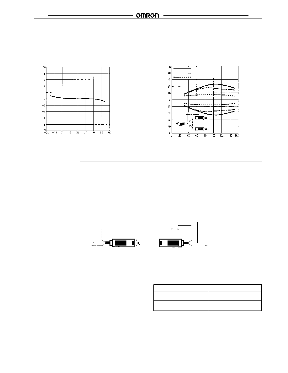
E4B-LS70E4, E4B-RS70E4
E4B-T1E4
V
a
r
i
at
i
o
n
r
at
e
o
f
s
ens
i
n
g
d
i
s
t
anc
e
(
%
)
Ambient temperature (∞C)
O
per
at
i
n
g
d
i
s
t
anc
e
Y
(
c
m
)
V
R
: Max.
V
R
: Center
V
R
: Min.
Setting distance X (cm)
J
AMBIENT TEMPERATURE VS.
VARIATION RATE OF SENSING
DISTANCE (TYPICAL)
J
SENSITIVITY ADJUSTER POSITION
VS. PARALLEL MOVEMENT
CHARACTERISTICS
Installation
J
INDICATORS
1. STABILITY Indicator (Green)
When this indicator is lit, the ultrasonic input into the Receiver is
sufficient, or its interruption is small enough, to ensure the
smooth operation of the E4B. Do not operate the E4B when this
indicator is not lit.
2. SENSING Indicator (Red)
When this indicator is lit, the Receiver has ultrasonic input.
J
INDICATOR OF THROUGH-BEAM
EMITTER
1. Incident Indicator
Lit when ultrasonic signal detected.
To use this indicator of the Emitter as an SENSING indicator like
the indicator on the Receiver, connect the black lead wires of the
Emitter and Receiver together.
Emitter
100 mA max.
Receiver
Load
Black
Blue
Brown
Blue
Brown
Black
+12 to 24 V
0 V
+12 to 24 V
0 V
Note: Be sure not to make mistakes in polarity when connecting the above wires. In other words, both brown lead wires must connect to
+VDC or 0 V and both blue lead wires must connect to 0 V or +VDC. Otherwise, the indicator of the Emitter will be lit when the
ultrasonic beam is interrupted.
2. Power Indicator
Lit when the E4B is turned ON.
If the above connections are not possible (e.g., the Receiver and
Emitter use different power supplies), this indicator will be used
as a power indicator.
Connections of Black (White) Lead Wire of Emitter
Power connection example
Brown: +VDC
Blue: 0 V
Brown: 0 V
Blue: +VDC
0 V blue
+VDC blue
Note: The indicator will not be lit if the above wires are not con-
nected correctly.

E4B
E4B
8
J
BEAM AXIS, SENSITIVITY, AND
DISTANCE ADJUSTMENTS
1. E4B-T1 and E4B-TS50 Through-beam Models
Set the SENSITIVITY adjuster of the Receiver to maximum.
Move the Emitter and Receiver vertically and horizontally until the
SENSING indicator of the Receiver is lit and secure the Emitter
and Receiver at the midpoint of the range within which the
STABILITY indicator is lit.
Optimum line
Range in which the STABILITY indicator (green) is lit
Range in which the SENSING indicator (red) is lit
Pass the sensing object through the sensing range and adjust
the sensitivity so that the SENSING indicator turns ON and OFF
according to the presence or absence of the sensing object while
the STABILITY indicator is lit continuously.
If the STABILITY indicator is not lit while the Sensor is in
operation, this may indicate a possible operational error. Check
or readjust the sensitivity.
If the Emitter and Receiver are set at a distance shorter than the
rated sensing distance, reduce the sensitivity to within the range
in which the STABILITY indicator is lit. This will increase the
immunity of the Sensor against noise.
The parallel movement characteristics (i.e., the mutual
interference distance) and sensing object size vary with the
sensitivity adjustment. Refer to Engineering Data and make the
optimum adjustments.
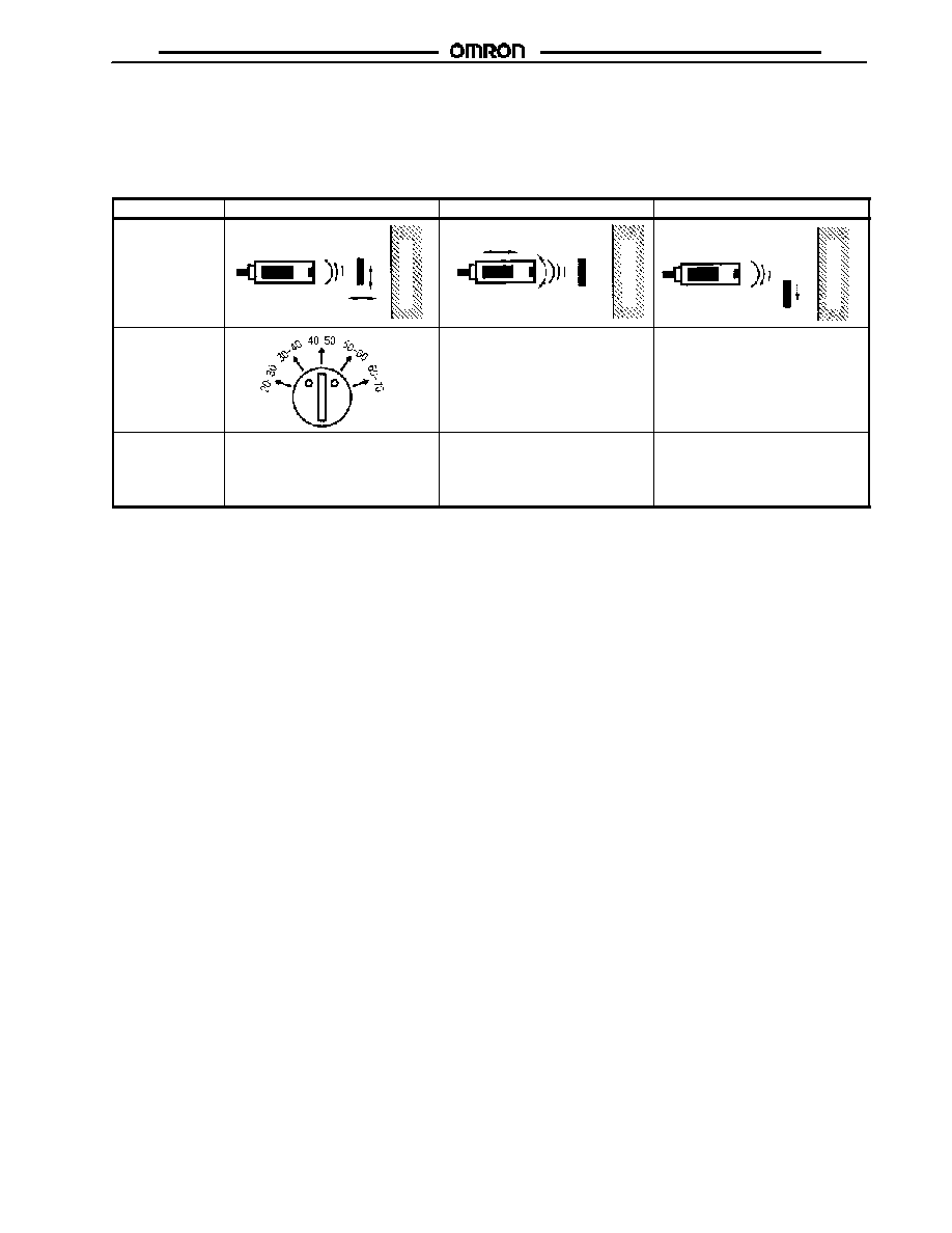
2. E4B-LS20 and E4B-LS70 Distance Setting Models
Locate the Sensor so that both the STABILITY and SENSING indicators will be lit when the object is placed at the sensing position, and
the STABILITY indicator will be lit and the SENSING indicator will turn OFF when the object is removed.
Step
1
2
3
Sensing
S
ens
ing
objec
t
B
a
c
k
g
r
ound
S
ens
ing
objec
t
B
a
c
k
g
r
ound
S
ens
ing
objec
t
B
a
c
k
g
r
ound
Distance adjuster
---
---
Adjustment
procedure
Place the sensing object at the
sensing position and turn the
distance adjuster clockwise
gradually until both the SENSING
and STABILITY indicators are lit.
Rotate the sensor vertically and
horizontally and secure the sensor
at the midpoint of the range within
which the STABILITY indicator is on.
Remove the sensing object and
check that the SENSING indicator is
OFF and the STABILITY indicator is
continuously on.
Note: If the STABILITY indicator is not lit while the Sensor is in operation, this indicates a possible operational error. Check or readjust
the sensitivity.
E4B-LS20
The sensing distance is adjustable within a range of 10 to 20 cm
with the distance adjuster.
Sensing
distance
Position of distance adjuster
5 to 10 cm
Set to the position 5-20. The distance range will
be 5 to 23 cm in this case due to the
characteristics of the ultrasonic beam.
10 to 20 cm
The adjuster can be set freely within a range of
10 to 20 cm. The object can be detected within a
range of 5 to 10 cm in this case due to multiple
ultrasonic reflection.
Setting sensing range (cm)
S
ens
ing
objec
t
Unstable range
Separate them 30 cm min.
B
a
c
k
g
r
ound
E4B-LS20
E4B
E4B
9
3. E4B-RS70 Reflective Zone
Target Reflective
Locate the Sensor so that both the STABILITY and SENSING indicators will be lit when the sensing object is placed at the sensing posi-
tion and the STABILITY indicator will be lit and the SENSING indicator will be off when the sensing object is removed.
Step
1
2
3
Sensing
S
ens
ing
objec
t
B
a
c
k
g
r
ound
S
ens
ing
objec
t
B
a
c
k
g
r
ound
S
ens
ing
objec
t
B
a
c
k
g
r
ound
Distance selector
---
---
Adjustment
procedure
Place the sensing object at the
sensing position and turn the
distance selector clockwise
gradually until both the SENSING
and STABILITY indicators are lit.
Rotate the sensor vertically and
horizontally and secure the sensor
at the midpoint of the range within
which the STABILITY indicator is on.
Remove the sensing object and
check that the SENSING indicator is
OFF and the STABILITY indicator is
continuously on.
Note: 1. If the STABILITY indicator is not lit while the Sensor is in operation, this indicates a possible operational error. Check or readjust
the sensitivity.
2. If the background object is within a distance of 1.5 m from the sensing head, the SENSING indicator may be lit and the STABILITY
indicator may not be lit in spite of the absence of the sensing object. Sensitivity should be reduced until STABILITY indicator turns
on. Re-check operation with object present. If stable operation still does not occur, background may need to be relocated.

E4B
E4B
10
Background Reflective
This method allows the stable detection of objects under irregular
and unstable reflection conditions (e.g., if the sensing objects are
different in surface or size, if they are passed through diagonally,
or if they are sound absorbant).
The sensor is adjusted to detect the background, Acoustic
Reflector, rather than the target directly. When the target is
present, it blocks detection of the Acoustic Reflector.
Reflector
Sensing range (20 to 55 cm)
: Near the midpoint of the sensing range (e.g., 45, 55, or 65 cm)
E4B-RS70
The Acoustic Reflector must be at least 4 x 4 cm in size and
made of a material that is efficiently reflective (such as a metal
plate).
Be sure that the target is not set within the sensing range.
Set the distance selector to the desired position, fix the reflector
around the midpoint of the set sensing range, and check that
both the SENSING and STABILITY indicators are lit.
Step
1
2
3
Sensing
Reflector
Set zone
Reflector
Reflector
Sensing object
Distance selector
---
---
Adjustment
procedure
Set the distance selector to the
desired zone position, mount the
Reflector at or near the midpoint of
the set zone, and confirm that both
the STABILITY and SENSING
indicators are on.
Rotate the sensor vertically and
horizontally and secure the Emitter
and Receiver at the midpoint of the
range within which the STABILITY
indicator is on.
Remove the sensing object and
check that the SENSING indicator is
OFF and the STABILITY indicator is
continuously on.
Note: 1. If the STABILITY indicator is not lit while the Sensor is in operation, this indicates a possible operational error. Check or readjust
the sensitivity.
2. If the object is in position A parallel to the Reflector as shown above, the SENSING indicator may be lit and the STABILITY
indicator may not be lit depending on the position of the sensing object. In such a case, give priority to the adjustment of the
STABILITY indicator when the beam is incident by means of the reflector.
E4B
E4B
11
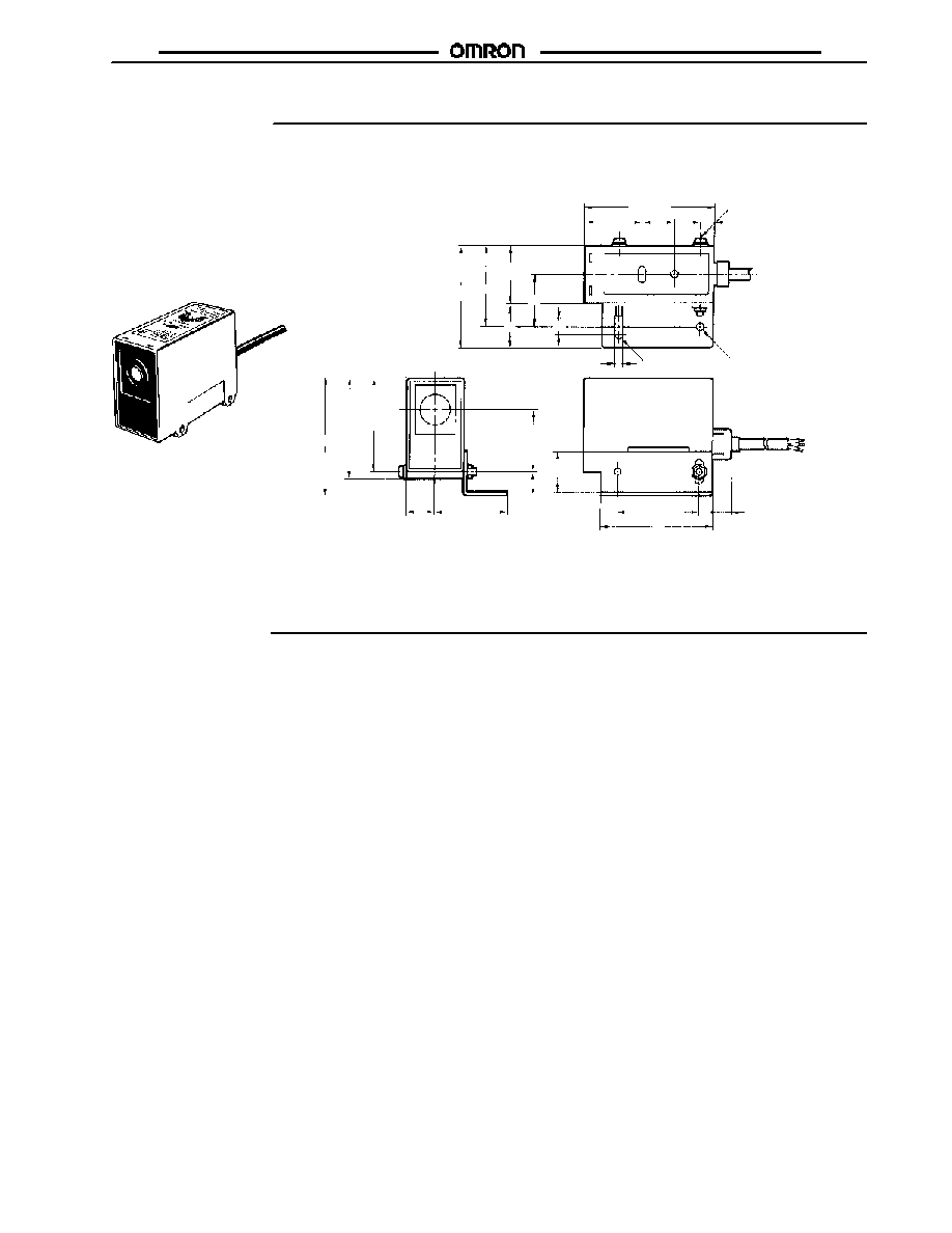
Dimensions
Unit: mm (inch)
J
E4B-TS50
E4B-T1
E4B-LS20
E4B-LS70
E4B-RS70
Two, M4 x 45
4.5 dia.
(See Note.)
Note: Vinyl-insulated round cable
with three conductors, 6 dia.;
standard length: 2 m
62
49.5
35
(1.38)
25
32
10
35
79 (3.11)
20
8
5
R2.5
25
66
50 (1.97)
8
11.5
71.5
61
(2.40) 57
17.5
44.5
11.5
38
Precautions
J
SENSOR MOUNTING ANGLE
If the E4B is in level control or distance control of sensing
objects, the stability of signal detection will depend on the
sensing surface condition of the objects. Considering the repose
angle of the objects, mount the E4B so that the ultrasonic beam
and the sensing surface of each object meet at right angles to
each other.
J
SURROUNDING OBJECTS
Make sure that the Sensor is free from surrounding objects that
reflect the ultrasonic beam diffusion, otherwise the Sensor may
malfunction. In particular, pay the utmost attention so that no side
lobe of the ultrasonic beam will be reflected by such objects.
J
MOUNTING
Securely mount the E4B by using the nuts provided with the E4B
or the mounting holes of the E4B. Refer to Dimensions for
details.
Do not strike the Sensor with hammer or other object, otherwise
the E4B will no longer be water-resistant.
If the E4B is not mounted securely, the E4B may be damaged by
vibration or may not detect target objects accurately due to a
possible change in the mounting position.
E4B
E4B
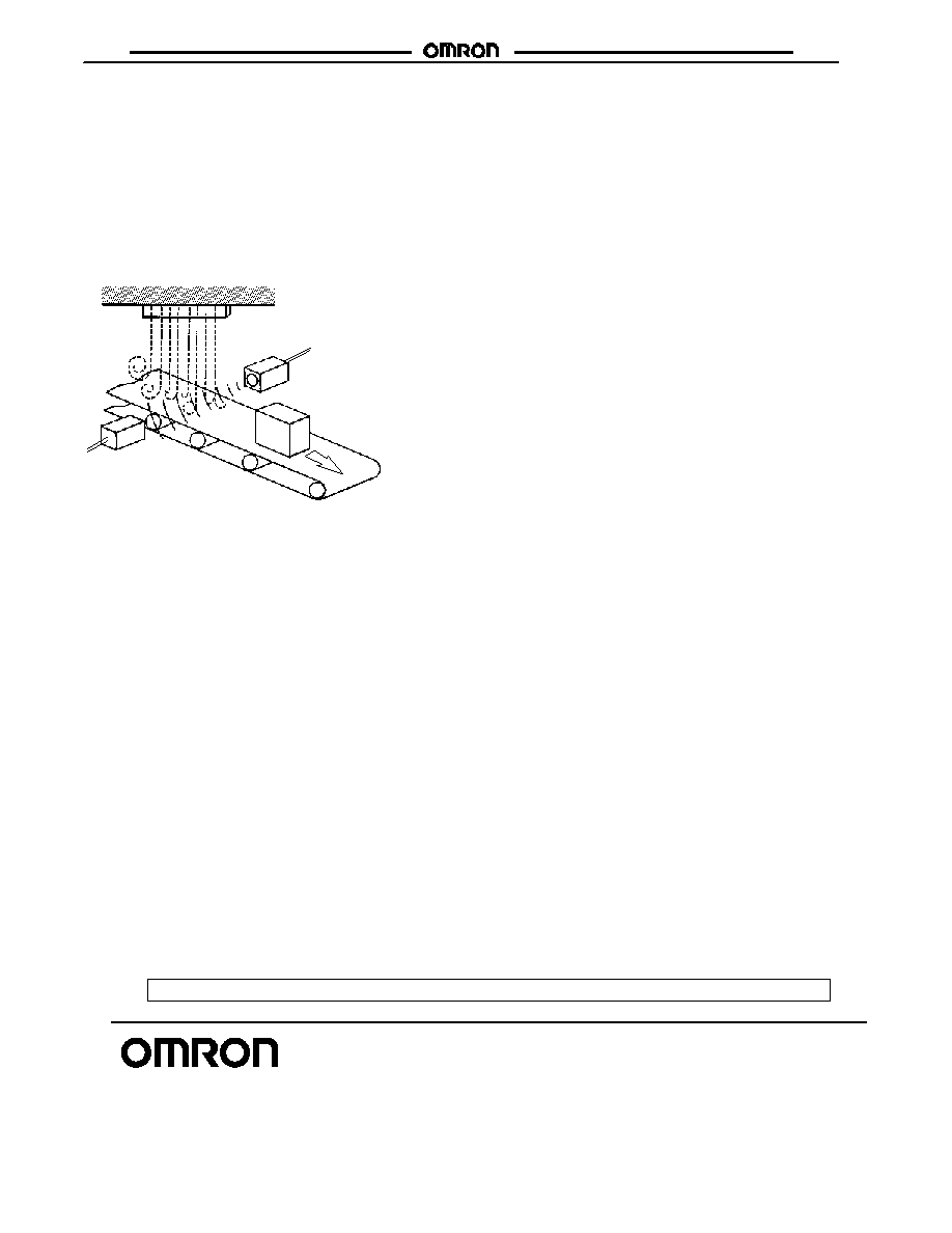
J
ENVIRONMENTAL CONDITIONS
Do not use the E4B at a temperature exceeding the rated range
or outdoors, otherwise the reliability and life of the E4B will
decrease.
The Ultrasonic Reflective Sensor utilizes the air as a beam
transmission media. Do not use the E4B in places with radical
convection or extreme local temperature changes. For example,
if there is a hot air curtain that causes turbulence within the
sensing area, the E4B may malfunction.
Turbulence
Air curtain
Emitter
Receiver
The jetting sound of air nozzles includes noise of a wide
frequency range, which will affect the operation of the E4B. Do
not use an air nozzle near the E4B.
The sensing distance of the E4B will decrease if there is any
water drops on the surface of the emitter or receiver.
The through-beam model may not detect any objects if there is
any object absorbing sound, such as powder and cotton, on the
surface of the emitter or receiver.
Cat. No. CEDSAX4 11/01 Specifications subject to change without notice. Printed in U.S.A.
OMRON ELECTRONICS LLC
One East Commerce Drive
Schaumburg, IL 60173
NOTE: DIMENSIONS SHOWN ARE IN MILLIMETERS. To convert millimeters to inches divide by 25.4.
1-800-55-OMRON
OMRON CANADA, INC.
885 Milner Avenue
Scarborough, Ontario M1B 5V8
416-286-6465
R
OMRON ON--LINE
Global -- http://www.omron.com
USA -- http://www.omron.com/oei
Canada -- http://www.omron.com/oci