Document Outline
- First Page
- Ordering Information
- Specifications
- Operation
- Engineering Data
- Dimensions
- Nomenclature
- Installation
- Precautions
- Contacting Omron

R
Ultrasonic 18 mm Cylindrical
E4C
Compact Through-Beam and
Reflective Models
H
Background suppression
H
NPN/PNP output, switch selectable
H
Mutual interference protection for
multiple units
H
DIN-rail mountable remote amplifier
Ordering Information
Description
Part number
Through-beam sensor
50 cm sensing distance
E4C-TS50
Reflective sensor
10 to 35 cm sensing distance
E4C-LS35
Amplifier for E4C-TS50
12 to 24 VDC supply voltage
E4C-WH4T
Amplifier for E4C-LS35
E4C-WH4L
J
ACCESSORIES
Description
Part number
Connector between two amplifiers
E99-C
Switching power supply
0.25 A, 12 VDC output, 100-240 VAC input
S82K-00312
0.13 A, 24 VDC output, 100-240 VAC input
S82K-00324

E4C
E4C
2
Specifications
J
RATINGS/CHARACTERISTICS
Sensors
Part number
E4C-TS50
E4C-LS35
Sensing method
Through-beam
Reflective
Sensing distance
50 cm (1.64 ft)
10 to 35 cm (3.94 to 13.78 in); possible to limit
the sensing zone within a range between 2 and
25 cm (0.79 to 9.84 in.)
Standard sensing object
10 x 10 cm flat plate
4 x 4 cm flat plate
Ultrasonic oscillation frequency
Approx. 270 kHz
Directional angle (See Note 1.)
�8� max.
Indicator
SENSING indicator (red LED)
Ambient operating temperature
--10�C to 55�C (14�F to 131�F) with no icing
Relative operating humidity
35 to 95%
Vibration resistance
10 to 55 Hz, 1.5-mm double amplitude for 2 hours each in X, Y, and Z axes
Shock resistance
500 m/s
2
(approx. 50G) 3 times each in X, Y, and Z axes
Enclosure rating
IEC IP66
Cable length
2 m
Weight
Approx. 300 g (with Emitter and Receiver)
Approx. 150 g
Material
Nut
Polyacetal resin
Material
Case
Heat-resistant ABS resin
Note: 1. Obtainable with a signal of -6 dB.
Amplifier Units
Part number
E4C-WH4T
E4C-WH4L
Compatible sensor
E3C-TS50
E3C-LS35
Supply voltage
(operating voltage range)
12 to 24 VDC �10% with a max. ripple �10% (p-p)
Current consumption
100 mA max. at 12 VDC
Differential travel
--
20% max. of rated sensing distance
Switching frequency (See Note.)
50 Hz
20 Hz
Response time
10 ms ON, 10 ms OFF
25 ms ON, 25 ms OFF
Control output (residual voltage)
100 mA max. (NPN and PNP open collector output at 40 VDC with a residual voltage of 2 V)
Operation mode
Normally open or normally closed (selectable with a slide switch)
Ultrasonic speed compensation
Yes
Indicator
SENSING indicator (red LED) and STABILITY indicator (green LED)
Ambient operating temperature
--10�C to 55�C (14�F to 131�F) with no icing
Relative operating humidity
35 to 95%
Note: The response frequencies are values obtained with the E4C used for detecting the rotating propeller-shaped disc as shown below.
Space:blade = 1:1
(This table continues on the next page.)
E4C
E4C
3
Specifications Table
-- continued from previous page
Part number
E4C-WH4T
E4C-WH4L
Temperature influence
�30% max. of sensing distance at 20�C (68�F)
in the temperature range of --10�C and 55�C
(14�F to 131�F)
�10% max. of sensing distance at 20�C (68�F)
in the temperature range of --10�C and 55�C
(14�F to 131�F)
Voltage influence
�10% max. of sensing distance at a voltage between 90% and 110% of the rated power supply
voltage
Insulation resistance
20 M min. (at 500 VDC) between current carry parts and case
Dielectric strength
1,000 VAC (50/60 Hz) for 1 min between current carry parts and case
Vibration resistance
10 to 55 Hz, 1.5-mm double amplitude for 2 hours each in X, Y, and Z directions
Shock resistance
500 m/s
2
(approx. 50G) 3 times each in X, Y, and Z directions
Enclosure rating
IEC IP40
Approvals
UL, cUL
Recognized, File No. E41515 when used with Class 2 power service
Weight
Approx. 110 g
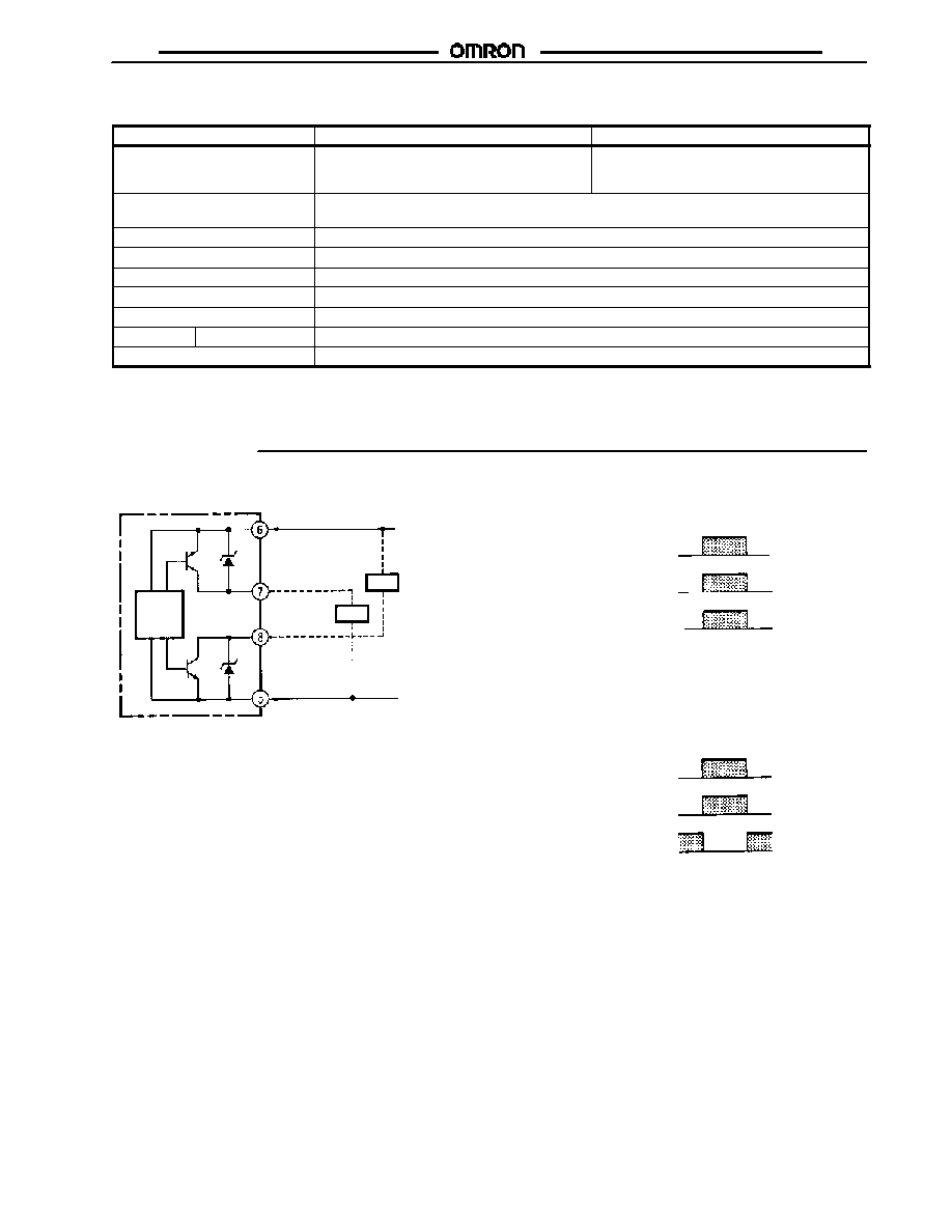
Operation
J
OUTPUT CIRCUIT
J
OPERATION SELECTOR (H1/H2)
100 mA max.
Load
Load
100 mA max.
PNP output
NPN output
E4C
main
circuit
12 to 24 V
0 V
Incident
Interrupted
SENSING indicator (red)
ON
OFF
Output transistor
(Both PNP and NPN outputs)
ON
OFF
Signal received-output ON (H1)
J
AMPLIFIER UNITS
Indicators
�
STABILITY Indicator (Green)
When this indicator is lit, the ultrasonic input into the Receiver is
sufficient, or its interruption small enough, to ensure the smooth
operation of the E4C. Do not operate the E4C when this indicator
is not lit.
�
SENSING Indicator (Red)
When this indicator is lit, the Receiver has ultrasonic input.
Signal received-output OFF (H2)
Incident
Interrupted
SENSING indicator (red)
ON
OFF
Output transistor
(Both PNP and NPN outputs)
ON
OFF
E4C
E4C
4
J
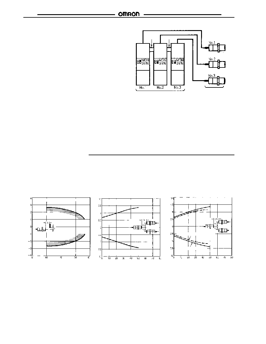
ASYNCHRONOUS/SYNCHRONOUS
(MON/SYN) SWITCH
�
If more than one Sensor is used in one place, the Sensors
need to be in synchronous operation for the prevention of
mutual interference. A maximum of four Sensors can be in
synchronous operation.
�
Connect the DC power supply and Sensor to each Amplifier
as usual.
�
Use the E99-C (order separately) connector to connect the
Sensor to the Amplifier.
�
If the case of the connections shown in the following illustra-
tion, set the selector of only one Amplifier (No. 1 in the follow-
ing case) to MON. Set the selector of any other Amplifier to
SYN. In "MON" mode, the amplifier generates a pulse. In
"SYN" mode, the pulse is inhibited.
E99-C Connector
(order separately)
(See Note.)
Amplifiers
Sensors
(See Note.)
(See Note.)
Note: The load in operation is connected to the output circuit of
the E4C.
Note: The E99-C Connector will be most effective if the E4C is a
reflective model although the E99-C Connector is required
by both the reflective and through-beam models. When
using through-beam models, however, be sure to maintain
enough space between adjacent Sensors to suppress
mutual interference. Refer to Sensitivity Adjuster Position
vs. Parallel Movement Characteristics in Engineering
Data.
Engineering Data
E4C-LS35
S
ens
i
n
g
r
ange
Y
(
c
m
)
Sensing distance X (cm)
E4C-TS50
O
per
at
i
n
g
d
i
s
t
anc
e
Y
(
c
m
)
Power supply voltage: 12 VDC
Sensitivity Adjuster: Max.
Obtain the point that turns Y
1
and Y
2
ON
while changing the sensing distance (X).
Setting distance X (cm)
Standard sensing object (4 x 4 cm flat plate)
Operating range
Operating range
J
SENSING RANGE
(TYPICAL)
J
PARALLEL MOVEMENT
CHARACTERISTICS
(TYPICAL)
J
SENSITIVITY ADJUSTER
POSITION VS. PARALLEL
MOVEMENT
CHARACTERISTICS
E4C-TS50+E4C-WH-4T
O
per
at
i
n
g
d
i
s
t
anc
e
Y
(
c
m
)
Setting distance X (cm)
Obtain the point that turns Y
1
and Y
2
ON
while changing the sensing distance (X).
Sensitivity adjuster: Center
Sensitivity adjuster: Max.
E4C
E4C
5
J
OPERATING DISTANCE VS. SENSING
OBJECT SIZE (TYPICAL)
E4C-LS35
S
ens
i
n
g
obj
ec
t
d
i
a
.
d
(
c
m
)
Sensing adjuster: 10
Zone adjuster: 25
Sensing object:Column
Dia.: d (cm)
Setting distance X (cm)
Operating range
E4C-TS50
S
ens
i
n
g
obj
ec
t
d
i
a
.
d
(
c
m
)
Sensitivity adjuster: Max.
Receiver
Sensing object (dia. d mm)
Emitter
Object passing position X (cm)
Operating range
J
OPERATING DISTANCE
VS. SENSING OBJECT
ANGLE (TYPICAL)
E4C-LS35
A
ngl
e
(
)
�
Operating distance X (cm)
Distance adjuster: 10
Zone adjuster: 25
Operating range
�
V
a
r
i
at
i
o
n
r
at
e
o
f
s
ens
i
n
g
d
i
s
t
anc
e
(
%
)
Sensor and Amplifier: Same temperature
variation
Sensitivity adjuster: Max.
Ambient temperature (�C)
J
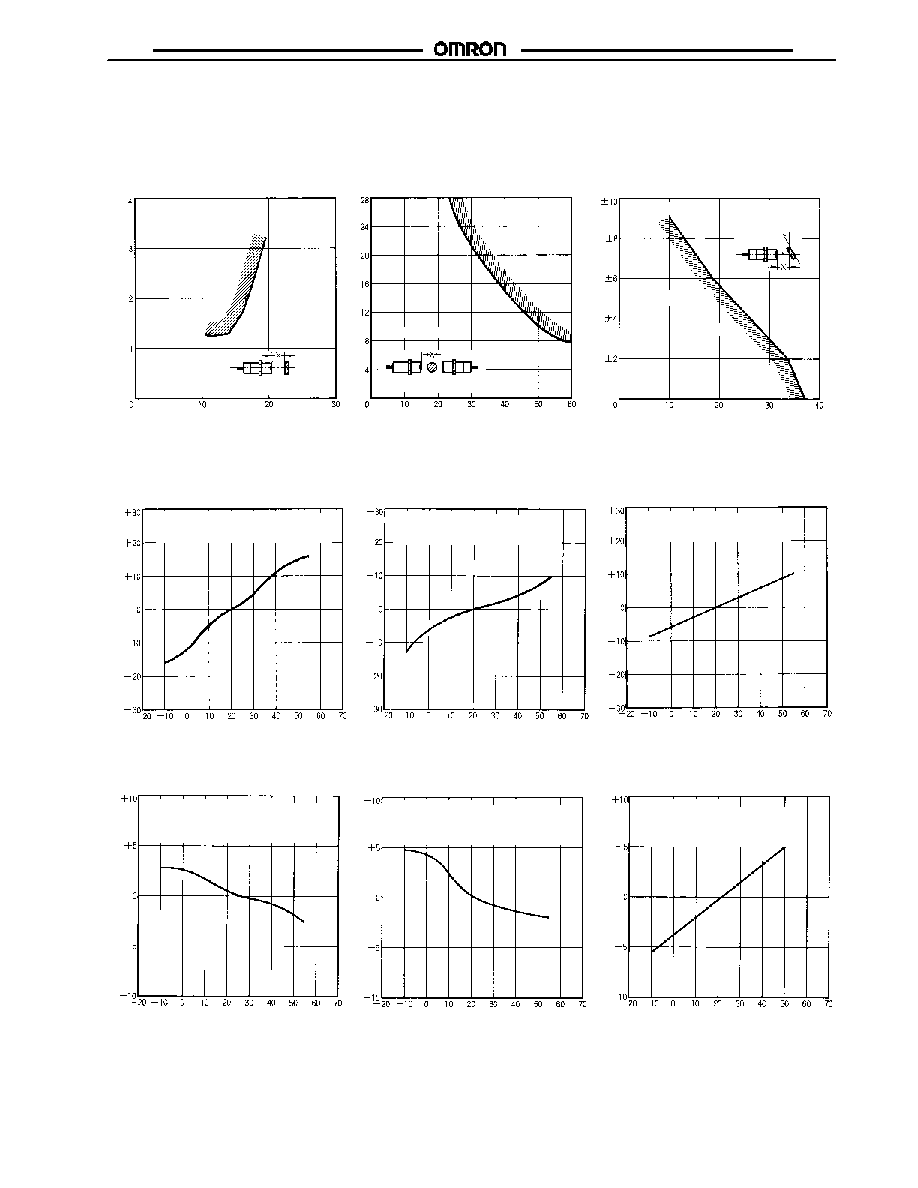
AMBIENT TEMPERATURE VS. VARIATION RATE OF SENSING DISTANCE (TYPICAL)
E4C-TS50+ E4C-WH4T
E4C-TS50+E4C-WH4T
Sensor: Temperature varied
Amplifier: Constant room temperature
Sensitivity adjuster: Max.
V
a
r
i
at
i
o
n
r
at
e
o
f
s
ens
i
n
g
d
i
s
t
anc
e
(
%
)
Ambient temperature (�C)
Ambient temperature (�C)
V
a
r
i
at
i
o
n
r
at
e
o
f
s
ens
i
n
g
d
i
s
t
anc
e
(
%
)
E4C-TS50+E4C-WH4T
Sensor: Constant room temperature
Amplifier: Temperature varied
Sensitivity adjuster: Max.
V
a
r
i
at
i
o
n
r
at
e
o
f
s
ens
i
n
g
d
i
s
t
anc
e
(
%
)
Ambient temperature (�C)
E4C-LS35+E4C-WH4L
Sensor and Amplifier: Same temperature
variation
Distance adjuster: 10
Zone adjuster: 25
Ambient temperature (�C)
V
a
r
i
at
i
o
n
r
at
e
o
f
s
ens
i
n
g
d
i
s
t
anc
e
(
%
)
E4C-LS35+E4C-WH4L
E4C-LS35+E4C-WH4L
Sensor: Temperature varied
Amplifier: Constant room temperature
Distance adjuster: 10
Zone adjuster: 25
Ambient temperature (�C)
V
a
r
i
at
i
o
n
r
at
e
o
f
s
ens
i
n
g
d
i
s
t
anc
e
(
%
)
Sensor: Constant room temperature
Amplifier: Temperature varied
Distance adjuster: 10
Zone adjuster: 25

E4C
E4C
6
Dimensions
Unit: mm (inch)
J
SENSORS
E4C-TS50
E4C-LS35
SENSITIVITY indicator
Note: E4C-TS50R or E4C-LS35: 3-conductor, shielded cable (6 dia., UL2791) with 7/0.25 dia. (standard length: 2 m)
E4C-TS50S: 2-conductor, shielded cable (6 dia., UL20276) with 7/0.25 dia. (standard length: 2 m)
18.5 dia.
(0.73)
8 dia. 9 dia.
(See Note.)
Mounting Holes
24
4
47
65
1
10
75 (2.95)
11 dia.
M18X1
J
AMPLIFIER UNITS
E4C-WH4T and E4C-WH4L
Two, M4 screw mounting holes
Note: DIN rail mounting side
(See Note.)
Two, 4.5 dia.
Mounting Holes
4.5
22.5
75
66
75
(2.95)
50 26.5
65
73
80
(3.15)
12.5
13
12.7
(0.05)
64
(2.52)
62.5
Nomenclature
E4C-WH4T
E4C-WH4L
Asynchronous/Syn-
chronous (MON/SYN)
operation selector
Mode (H1/H2) selector
SENSING indicator
STABILITY indicator
Sensitivity adjuster
Asynchronous/Syn-
chronous (MON/SYN)
operation selector
Mode (H1/H2) selector
SENSING indicator
STABILITY indicator
Zone adjuster
Distance (sensing
distance) adjuster
E4C
E4C
7
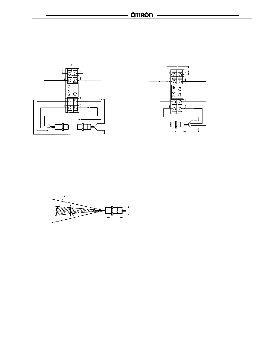
Installation
J
CONNECTIONS
E4C-WH4T
E4C-WH4L
12 to 24 VDC
Output 2 (PNP)
100 mA max.,
40 VDC max.
Output 1 (NPN)
100 mA max.,
40 VDC max.
Black
White
Red
Shield
12 to 24 VDC
Output 2 (PNP)
100 mA max.,
40 VDC max.
Output 1 (NPN)
100 mA max.,
40 VDC max.
Black
White
Red
Shield
E4C-LS35
E4C-TS50
(Blue)
(Black)
(Brown)
(Blue)
(Black)
(Brown)
J
SENSITIVITY/ZONE ADJUSTMENTS
E4C-TS50 and E4C-WH4T Through-beam Models
Set the SENSITIVITY adjuster of the Receiver to maximum.
Move the Emitter and Receiver vertically and horizontally until the
SENSING indicator of the Receiver is lit and secure the Emitter
and Receiver at the midpoint of the range within which the
STABILITY indicator is lit.
Range in which the STABILITY indicator (green) lit
Optimum line
Range in which the SENSING indicator (red) lit
Pass the target object through the sensing range and adjust the
sensitivity so that the SENSING indicator turns ON and OFF
according the presence or absence of the object while the
STABILITY indicator is lit continuously.
If the STABILITY indicator is not lit while the Sensor is in
operation, this may indicate a possible operational error. Check
or readjust the sensitivity.
If the Emitter and Receiver are set at a distance shorter than the
rated sensing distance, reduce the sensitivity to within the range
in which the STABILITY indicator is lit. This will increase the
immunity of the Sensor against noise.
E4C
E4C
8
J
E4C-LS35 AND E4C-WH4L CONVERGENT REFLECTIVE MODEL
Locate the Sensor so that both the STABILITY and SENSING indicators will be lit when the sensing object is placed at the sensing posi-
tion, and the STABILITY indicator will be lit and the SENSING indicator will turn OFF when the sensing object is removed.
Step
1
2
3
4
Sensing
B
a
c
k
g
r
ound
S
ens
ing
objec
t
B
a
c
k
g
r
ound
S
ens
ing
objec
t
B
a
c
k
g
r
ound
S
ens
ing
objec
t
B
a
c
k
g
r
ound
S
ens
ing
objec
t
35 cm
Distance adjuster
Zone adjuster
---
---
Adjustment
procedure
Place the sensing object
at the sensing position and
turn the distance adjuster
clockwise gradually until
both the SENSING and
STABILITY indicators are
lit. (See note 2)
Move the Emitter and
Receiver vertically and
horizontally and secure
the Emitter and Receiver
at the midpoint of the
range within which the
STABILITY indicator is lit.
Remove the sensing
object and check that the
SENSING indicator is OFF
and the STABILITY
indicator is continuously lit.
The sensing zone can be
set within a range of 2 to
25 cm with the zone
adjuster.
Note: 1. If the STABILITY indicator is not lit while the Sensor is in operation, this indicates a possible operational error. Check or readjust
the sensitivity.
2. The sensing distance is adjustable within a range of 10 to 35 cm with the distance adjuster.
3. Adjust the sensing zone within the sensing distance adjustable range (i.e., 10 to 35 cm).
J
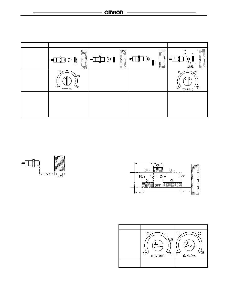
SENSING ZONE SETTING EXAMPLE
Sensing zone
Sensing distance
adjustment
Sensing zone
adjustment
Note: Make the settings as shown above to set a sensing zone
of 10 cm with a sensing distance adjustment of 15 cm.
J
SENSING ZONE CHART
Example:
Sensing distance set to 15 cm and zone set to 10 cm
Signal
Received
Signal Not
Received
Unstable
sensing zone
Stable sensingzone
(adjustable)
Non-sensing
zone
Sensing distance
adjustment
Sensing zone
adjustment
B
a
c
k
g
r
ound
objec
t
(Outside the ratings)
(Outside the ratings)
Note: Set the zone within a distance of 10 to 35 cm from the
Sensor. Therefore, if the distance adjuster is set to 30 cm
and zone adjuster is set to 20 cm, the sensing zone will
be 5 cm from a point 30 cm away from the Sensor.
Step
1
2
Distance
adjuster and
zone adjuster
Adjustment
procedure
Set the distance
adjuster to 15 cm
Set the zone adjuster
to 10 cm.

E4C
E4C
9
Precautions
J
SENSOR MOUNTING ANGLE
If the E4C is in level control or distance control of sensing
objects, the stability of signal detection will depend on the
sensing surface condition of the objects. Considering the repose
angle of the objects, mount the E4C so that the ultrasonic beam
and the sensing surface of each object meet at right angles to
each other.
J
SURROUNDING OBJECTS
Make sure that the Sensor is free from surrounding objects that
reflect the ultrasonic beam diffusion, or the Sensor may
malfunction. In particular, pay the utmost attention so that no side
lobe of the ultrasonic beam will be reflected by such objects.
J
MOUNTING
Securely mount the E4C by using the nuts provided with the E4C
or the mounting holes of the E4C. Refer to Dimensions for
details.
Do not strike the Sensor with any hammer or other object,
otherwise the E4C will no longer be water-resistant.
If the E4C is not mounted securely, the E4C may be damaged by
vibration or may not detect sensing objects accurately due to a
possible change in the mounting position.
J
ENVIRONMENTAL CONDITIONS
Do not use the E4C at a temperature exceeding the rated range
or outdoors, otherwise the reliability and life of the E4C will
decrease.
The Ultrasonic Reflective Sensor utilizes the air as a beam
transmission media. Do not use the E4C in places with radical
convection or extreme local temperature changes. For example,
if there is a hot air curtain that causes turbulence within the
sensing area, the E4C may malfunction.
Turbulence
Air curtain
Emitter
Receiver
The jetting sound of air nozzles includes noise of a wide
frequency range, which will affect the operation of the E4C. Do
not use an air nozzle near the E4C.
The sensing distance of the E4C will decrease if there is any
water drops on the surface of the emitter or receiver.
The reflective model may not detect any objects if there is any
object absorbing sound, such as powder and cotton, on the
surface of the emitter or receiver.
J
MUTUAL INTERFERENCE
If more than one Unit is closely mounted together or used in a
narrow space, the mutual interference of the Sensors will result.
To prevent this, set the MON/SYN selector to SYN and check
that no mutual interference results.
J
CONNECTIONS
The cord length between the Sensor and Amplifier can be a
maximum of 20 m provided that the cord is a three-conductor,
shielded cord (6 dia., UL2791) with 7/0.25 dia. If the Emitter is the
E4C-TS50S, however, use a two-conductor, non-shielded cord
(6 dia. UL20276) with 7/0.25 dia.
Do not wire the lines of the E4C along with high-tension or power
lines in the same conduit or close together, otherwise the E4C
may malfunction due to inductive noise.
The power supply lines of the Amplifier can be extended up to
100 m provided that the size of the cord is 0.3 dia. or more.
J
ADDITIONAL PRECAUTIONS
Be sure not to turn the sensitivity adjuster excessively. If the
sensitivity adjuster is turned exceeding the permissible range, no
sensitivity adjustment will be possible again.
Take the measures shown in the following illustrations if multiple
reflection results.
Urethane rubber or sponge
Wall
5-dia. slit
Wall
The sensing distance will be, however, reduced to half (i.e., 10 to
17 cm) if the slit is used.
If the sensing zone is set to a small value (i.e., a few centimeters)
on the E4C reflective model, the E4C may require a warming-up
time of 3 minutes or more after the E4C is turned ON.

Cat. No.
CEDSAX4
11/01
Specifications subject to change without notice. Printed in U.S.A.
OMRON ELECTRONICS LLC
One East Commerce Drive
Schaumburg, IL 60173
NOTE: DIMENSIONS SHOWN ARE IN MILLIMETERS. To convert millimeters to inches divide by 25.4.
1-800-55-OMRON
OMRON CANADA, INC.
885 Milner Avenue
Scarborough, Ontario M1B 5V8
416-286-6465
R
OMRON ON--LINE
Global -- http://www.omron.com
USA -- http://www.omron.com/oei
Canada -- http://www.omron.com/oci
E4C
E4C