Document Outline
- First Page
- Ordering Information
- Specifications
- Operation
- Engineering Data
- Dimensions
- Installation
- Precautions
- Contacting Omron
R
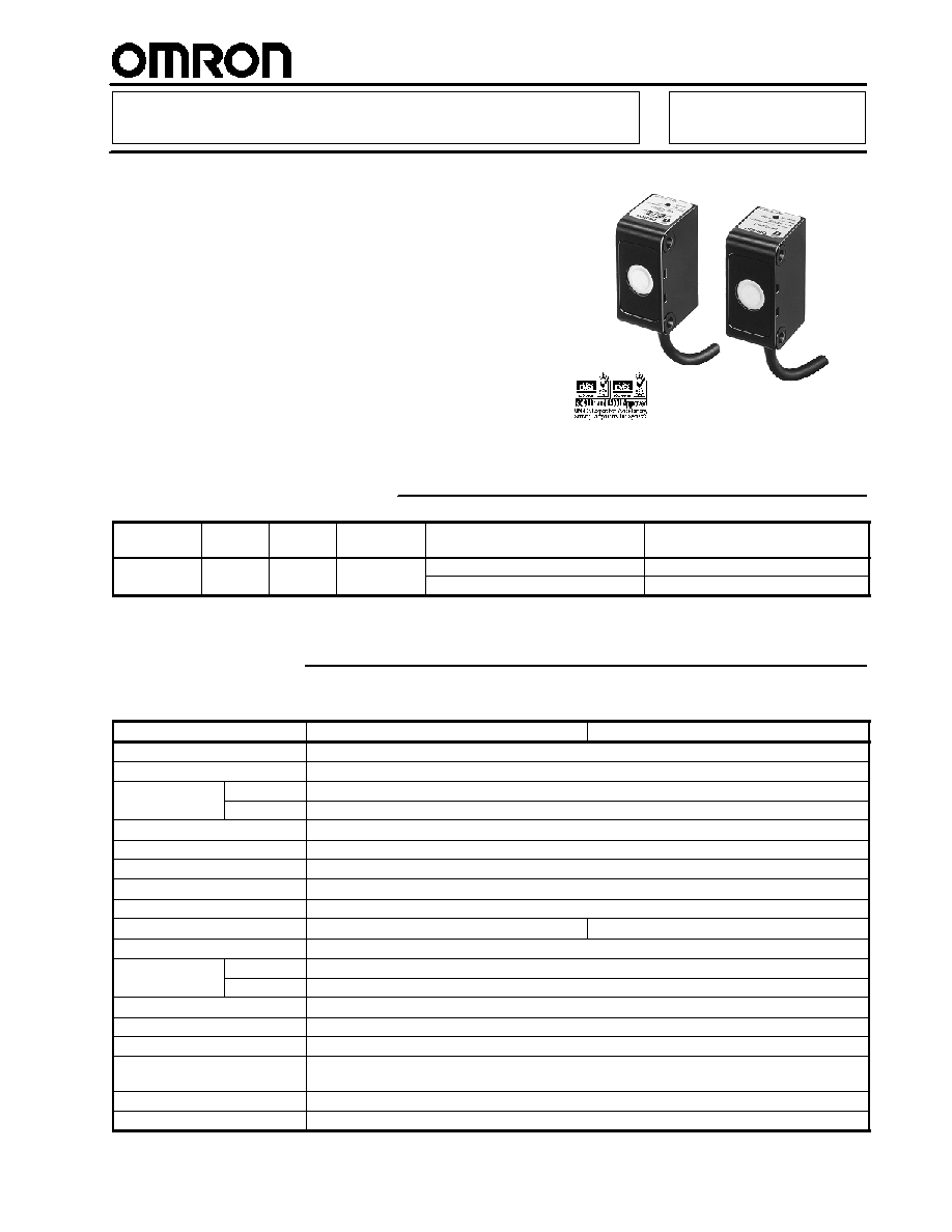
Compact Ultrasonic Sensor
E4E
Through-Beam Sensor with
Built-in Amplifier
H
Compact size
H
Fully-potted IP66, resists shock and
vibration
H
Easy-to-use sensitivity adjustment
H
No separate amplifier required
Ordering Information
Supply
voltage
Sensing
type
Sensing
distance
Cable length
Output configuration
Part number
12 to 24 VDC
Through-
30 cm
2 m
NPN-NO open collector
E4E-TS30C1
12 to 24 VDC
Through
beam
30 cm
2 m
NPN-NC open collector
E4E-TS30C2
Note: Model E4E-TS30C1-1 with no indicator is available for photo film detection applications.
Specifications
J
RATINGS/CHARACTERISTICS
Part number
E4E-TS30C1
E4E-TS30C2
Sensing method
Through beam
Sensing method
Through-beam
Supply voltage
12 to 24 VDC --10%/+15% (10.8 to 27.6 V) with a max. ripple of �10% (p-p)
Current
Emitter
20 mA max. at 24 VDC
Current
consumption
Receiver
30 mA max. at 24 VDC
Sensing distance
30 cm (11.81 in)
Standard sensing object
40 x 40 mm
Ultrasonic oscillation frequency
Approx. 270 kHz
Response frequency
20 Hz max.
Response time
25 ms on, 25 ms off
Control output
NPN-NO, 100 mA max. at 30 VDC
NPN-NC, 100 mA max. at 30 VDC
Residual voltage
1.0 V
Indicator
Emitter
POWER indicator (green LED)
Indicator
Receiver
OPERATION indicator (with control output ON) and Sensitivity indicator (red LED)
Ambient operating temperature
0�C to 50�C (32�F to 122�F) with no icing
Storage temperature
--10�C to 60�C with no icing
Relative humidity
35% to 95%
Temperature influence
�10% max. of sensing distance at 20�C (68�F) in the temperature range of 0�C to 50�C
(32�F to 122�F)
Insulation resistance
100 M min. at 500 VDC between current carrying parts and case
Dielectric strength
1500 VAC, 50/60 Hz for 1 min between current carrying parts and case
(This table continues on the next page.)
E4E
E4E
2
Specifications Table
-- continued from previous page
Part number
E4E-TS30C1
E4E-TS30C2
Vibration resistance
10 to 55 Hz, 1.5-mm double amplitude for 2 hours each in X, Y, and Z axes
Shock resistance
500 m/s
2
(approx. 50G) once each in X, Y, and Z axes
Enclosure rating
IEC60529 IP66
Approvals
UL, cUL
Recognized, File No. E41515 when used with a Class 2 power supply
Weight
Approx. 120 g (Emitter and Receiver)
Material
Heat-resistant ABS resin
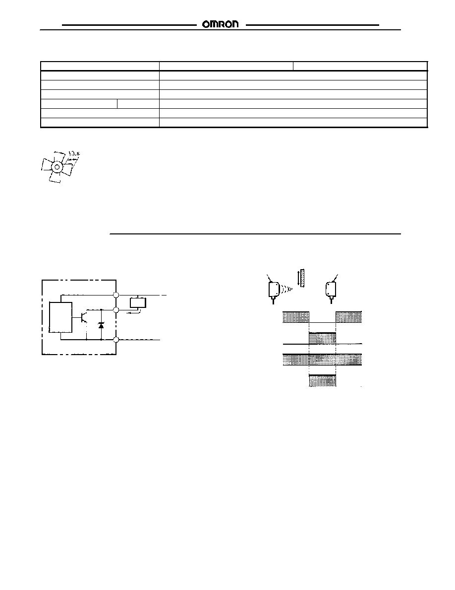
Note: The response frequencies are the values obtained with the E4E used for detecting the rotating propeller-shaped disc as shown to
here.
Space:Blade = 1:1
Operation
Main
circuit
Brown
Load
Black
(output)
Blue
100 mA max.
12 to 24 VDC
0 V
Green LED
Emitter
Sensing
object
Receiver
Signal received
Signal blocked
Control output
(NPN open collector)
POWER indicator
(green LED)
Sensitivity indicator
(red LED)
ON
OFF
ON
OFF
ON
OFF
Red LED
NPN Output
J
OUTPUT CIRCUITS (RECEIVER)
J
OPERATION CHART (N.O.)
PNP Output
(Not shown)
E4E
E4E
3
Engineering Data
J
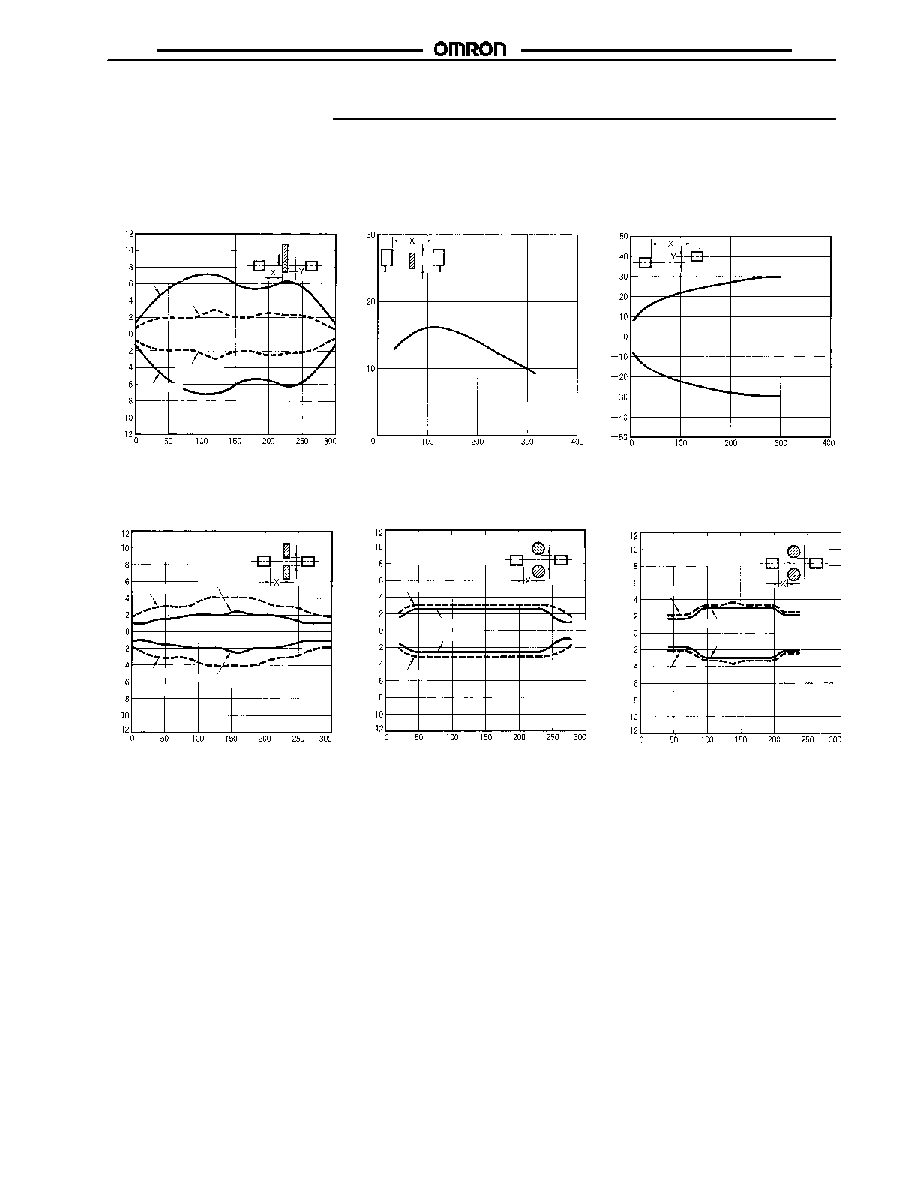
SENSING RANGE
DIAGRAM (TYPICAL)
J
OPERATING DISTANCE
VS. MINIMUM SENSING
OBJECT SIZE (TYPICAL)
J
PARALLEL MOVEMENT
(TYPICAL)
S
e
n
s
i
n
g
d
i
s
t
a
n
c
e
Y
(mm)
S
e
n
s
i
n
g
o
b
j
e
c
t
s
i
z
e
d
(mm)
Sensing distance X (mm)
Sensing distance X (mm)
Sensing distance X (mm)
O
p
e
r
a
t
i
n
g
d
i
s
t
a
n
c
e
Y
(mm)
Sensing object
Emitter
Receiver
ON point
ON point
OFF point
OFF point
Sensing object
j
d
Standard sensing object
40 x 40 x 2 mm SPCC plate
J
SLIT SENSING RANGE (TYPICAL)
Standard sensing object:
Two, 100 dia. x 200 mm
SPCC round rods
S
l
i
t
w
i
d
t
h
W
(mm)
*
Standard sensingobject:
Two, 100 x 100 x 2 mm
SPCC plates
Standard sensing
object
Emitter
Receiver
ON point
ON point
OFF point
OFF point
Sensing distance X (mm)
*Value W is the limit of jam detection.
*Value W is the limit of jam detection.
*Value W is the limit of jam detection.
S
l
i
t
w
i
d
t
h
W
(mm)
*
Standard sensing object:
Two, 50 dia. x 200 mm
SPCC round rods
Standard sensing
object
Emitter
Receiver
ON point
ON point
OFF point
OFF point
Sensing distance X (mm)
S
l
i
t
w
i
d
t
h
W
(mm)
*
Standard sensing
object
Emitter
Receiver
ON point
ON point
OFF point
OFF point
Sensing distance X (mm)
W*
W*
W*
E4E
E4E
4
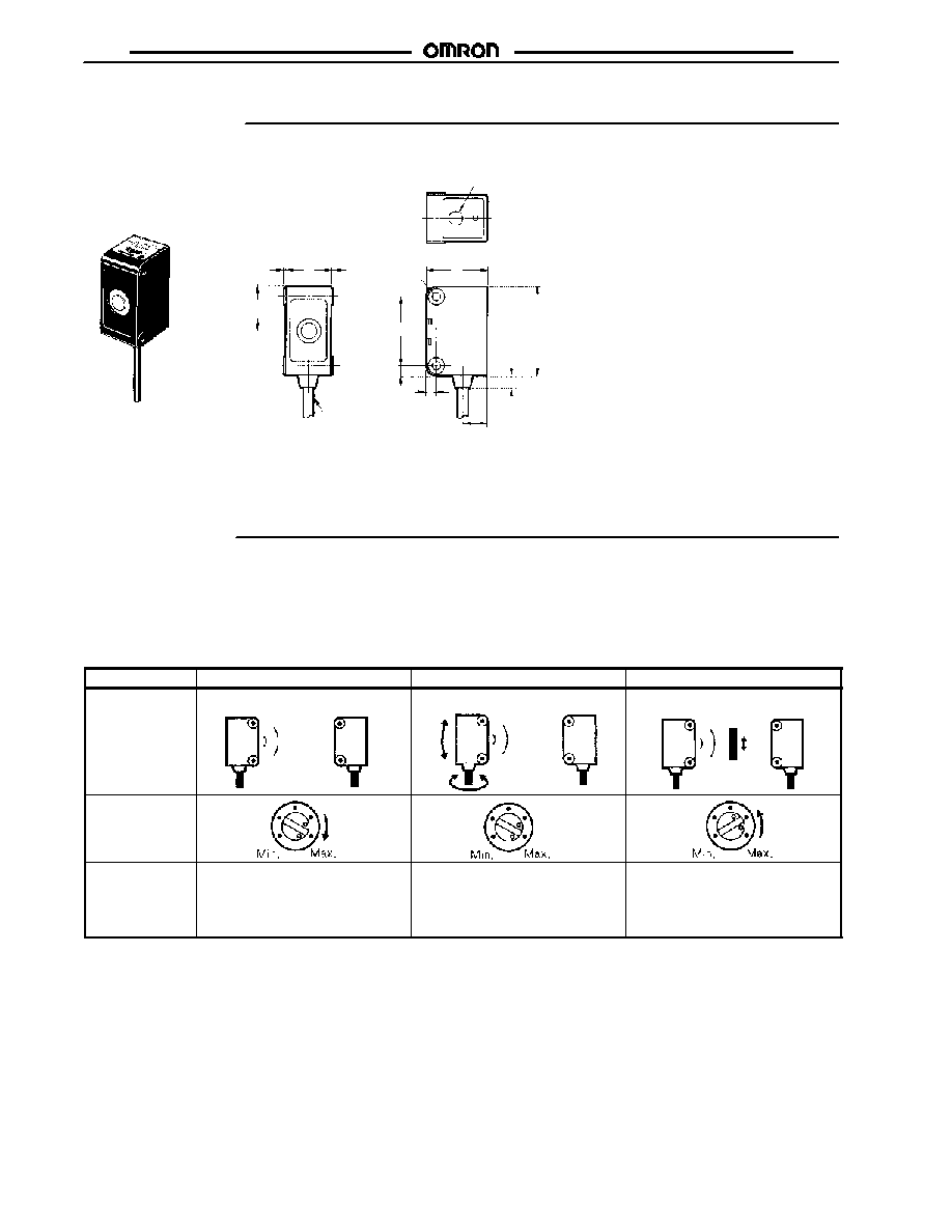
Dimensions
Unit: mm (inch)
Sensitivity adjuster (receiver only)
Note: Vinyl-insulated cable, 3.9 dia. Emitter has 2 conductors,
Receiver has 3 conductors
Two, 3.3-dia.
holes
(See Note.)
18
(0.71)
25
(0.98)
4
28
0.3
0.3
4
18
(0.71)
36
(1.42)
5
10
Installation
J
BEAM AXIS AND SENSITIVITY ADJUSTMENTS
�
Set the sensitivity adjuster of the Receiver to maximum.
�
Move the Emitter and Receiver vertically and horizontally and
secure the Emitter and Receiver in the center of the range
within which the OPERATION indicator is ON.
�
Let the sensing object pass through the sensing range and
adjust the sensitivity so that the OPERATION indicator is ON
and OFF.
Step
1
2
3
Sensing
Emitter
Receiver
Emitter
Receiver
Emitter
Receiver
Sensing object
Sensitivity
adjuster
Adjustment
procedure
Set the sensitivity adjuster of the
receiver to max.
Move the Emitter and Receiver
vertically and horizontally and
secure the Emitter and Receiver in
the center of the range within which
the OPERATION indicator is OFF.
Let the sensing object pass through
the sensing range and adjust the
sensitivity so that the OPERATION
indicator is ON and OFF.

E4E
E4E
Precautions
J
MUTUAL INTERFERENCE
If more than one Sensor is closely mounted together or used in a
narrow space, the mutual interference of the Sensors will result.
J
WIRING
Do not wire the lines of the E4E along with high-tension or power
lines in the same conduit or close together, otherwise the E4E
may malfunction due to inductive noise.
J
SENSITIVITY ADJUSTMENT
Be sure not to turn the sensitivity adjuster excessively. If the
sensitivity adjuster is turned exceeding the permissible range, no
sensitivity adjustment will be possible again.
J
POWER SUPPLY
If a standard switching regulator is used, ground the FG and G
terminals.
J
POWER ON
The E4E needs a maximum of 100 ms to be ready to operate
after the E4E is turned ON. If power is supplied to the E4E and
the load independently, be sure to turn ON the E4E first.
J
OUTPUT SHORT-CIRCUIT
The E4E has a built-in circuit protecting the output from
short-circuit damage. If the circuit is triggered, the output will not
operate. Turn OFF the E4E, check the condition of the load, and
then turn ON the E4E again.
Cat. No. CEDSAX4 11/01 Specifications subject to change without notice. Printed in U.S.A.
OMRON ELECTRONICS LLC
One East Commerce Drive
Schaumburg, IL 60173
NOTE: DIMENSIONS SHOWN ARE IN MILLIMETERS. To convert millimeters to inches divide by 25.4.
1-800-55-OMRON
OMRON CANADA, INC.
885 Milner Avenue
Scarborough, Ontario M1B 5V8
416-286-6465
R
OMRON ON--LINE
Global -- http://www.omron.com
USA -- http://www.omron.com/oei
Canada -- http://www.omron.com/oci