 | –≠–ª–µ–∫—Ç—Ä–æ–Ω–Ω—ã–π –∫–æ–º–ø–æ–Ω–µ–Ω—Ç: E8CB | –°–∫–∞—á–∞—Ç—å:  PDF PDF  ZIP ZIP |
Document Outline
- First Page
- Ordering Information
- Specifications
- Engineering Data
- Operation
- Dimensions
- Precautions
- Contacting Omron
R
2
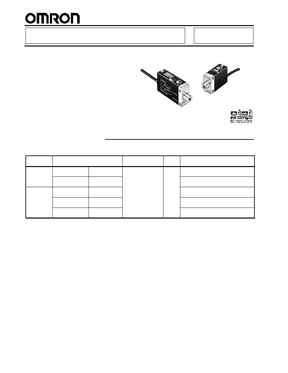
Pressure Sensor
E8CB/E8CC
Flat-pack, Slim, DIN-rail Mount
Pressure Sensor
H
Withstands a pressure of 490 kPa
(71 psi)
H
Easy pressure setting with a two-turn
pressure adjuster
H
Linear analog output
H
E8CC has digital display
Ordering Information
J
SENSOR
Digital display Pressure range
ON/OFF output
Linear
output
Part number
No
Positive pressure
0 to 98 kPa
(0 to 14.2 psi)
NPN open collector
1 to 5 V E8CB-01C
Negative pressure
0 to --101 kPa
(0 to --14.6 psi)
E8CB-CN0C2B
Yes
Positive pressure
0 to 98 kPa
(0 to 14.2 psi)
E8CC-A01C
Negative pressure
0 to --101 kPa
(0 to --14.6 psi)
E8CC-AN0C
Positive pressure
0 to 980 kPa
(0 to 142.1 psi)
E8CC-B10C
E8CB/E8CC
E8CB/E8CC
3
Specifications
J
RATINGS/CHARACTERISTICS
Item/Model
E8CB-01C
E8CB-
CN0C2B
(See Note 2.)
E8CC-A01C
E8CC-AN0C
(See Note 2.)
E8CC-B10C
Supply voltage
12 to 24 VDC ±10% with a ripple (p-p) of 5% max.
Current consumption
20 mA max.
30 mA max.
Pressure type
Gauge pressure
Permissible
Display value
0 to 1 kgf/cm
2
0 to --76 cmHg
0 to 98 kPa
0 to --101 kPa
0 to 980 kPa
Permissible
pressure range
(See Note 2.)
Reference
value
0 to 98 kPa
(0 to 14.2 psi)
0 to --101 kPa
(0 to --14.6 psi)
---
(0 to
14.2 psi)
---
(0 to --14.6 psi)
---
(0 to
142.1 psi)
Pressure setting range
(See Note 2.)
Display value
0 to 1 kgf/cm
2
0 to --76 cmHg
0 to
98 kPa
0 to --101 kPa
0 to
980 kPa
(
)
Reference
value
0 to 98 kPa
(0 to 14.2 psi)
0 to --101 kPa
(0 to --14.6 psi)
---
---
---
Pressure indication unit
---
kPa
Withstand pressure
490 kPa (71 psi)
490 kPa (71 psi)
1.5 MPa
(217.5 psi)
Applicable material
Noncorrosive and nonflammable gases
Repeat accuracy
(ON/OFF output)
±1% FS max.
Accuracy (linear output)
±3% FS max.
Differential travel
(ON/OFF output)
2% FS max.
Linearity (linear output)
±1% FS max.
Response time
5 ms max.
Linear output
1 to 5 V with an output impedance of 20 and a permissible resistive load of 10 k min.
ON/OFF output
NPN open collector
Load current
80 mA max.
Output applied
voltage
30 VDC max.
Residual
voltage
1 V max. (with a load current of 80 mA) and 0.4 V max. (with a load current of 20 mA)
Circuit protection
Reversed power supply connection and load short-circuiting
Display (See Note 1.)
Red LED ON with output
transistor turned ON
2
1
/
2
-digit display
Red LED ON with output transistor turned ON
Display accuracy
---
±3% FS ± 1 digit max. within a temperature range
from 0∞C to 50∞C
(32∞F to 122∞F)
±4% FS ± 1 digit max. within a temperature range
from 50∞C to 55∞C (122∞F to 131∞F)
±5% FS ± 1 digit max. within a temperature range
from 0∞C to --10∞C
(32∞F to 14∞F)
E8CB/E8CC
E8CB/E8CC
4
Item/Model
E8CB-01C
E8CB-
CN0C2B
(See
Note 2.)
E8CC-A01C
E8CC-AN0C
(See Note 2.)
E8CC-B10C
Ambient temperature
Operating: --10∞C to 55∞C (14∞F to 131∞F) with no icing
Ambient temperature
Storage: --25∞C to 70∞C (--13∞F to 158∞F) with no icing
Ambient humidity
Operating/Storage: 35% to 95% (with no icing)
Temperature influence
±0.12% FS/∞C between 0∞C and 50∞C (32∞F to 122∞F) and ±0.2% FS/∞C max. between --10∞C and
0∞C or 50∞C and 55∞C (122∞F to 131∞F)
Voltage influence
±1.5% FS max.
Insulation resistance
50 M min. (at 500 VDC) between current carrying parts and case
Dielectric strength
1,000 VAC for 1 min
Vibration resistance
10 to 500 Hz, 1.5-mm double amplitude or 100 m/s
2
(328 ft/s
2
) for 2 hours each in X, Y, and Z
directions
Shock resistance
1,000 m/s
2
(3280 ft/s
2
) 3 times each in X, Y, and Z directions
Degree of protection
(See Note 3.)
IEC60529 IP50
Pressure port
Aluminum
Connection method
Prewired (standard cable length: 2 m)
Weight
Approx. 70 g (2.47 oz)
Approx. 80 g (2.82 oz)
Pressure port
NPT 1/8 and M5 female screws
Note: 1. The 2
1
/
2
-digit display refers to a display in which the third digit displays only 0 or 1.
3rd digit
2nd digit 1st digit
0 or 1
0 to 9
0 to 9
2. These models are negative-pressure models.
3. E8CB and E8CC are not oil resistant or water resistant.
Engineering Data
J
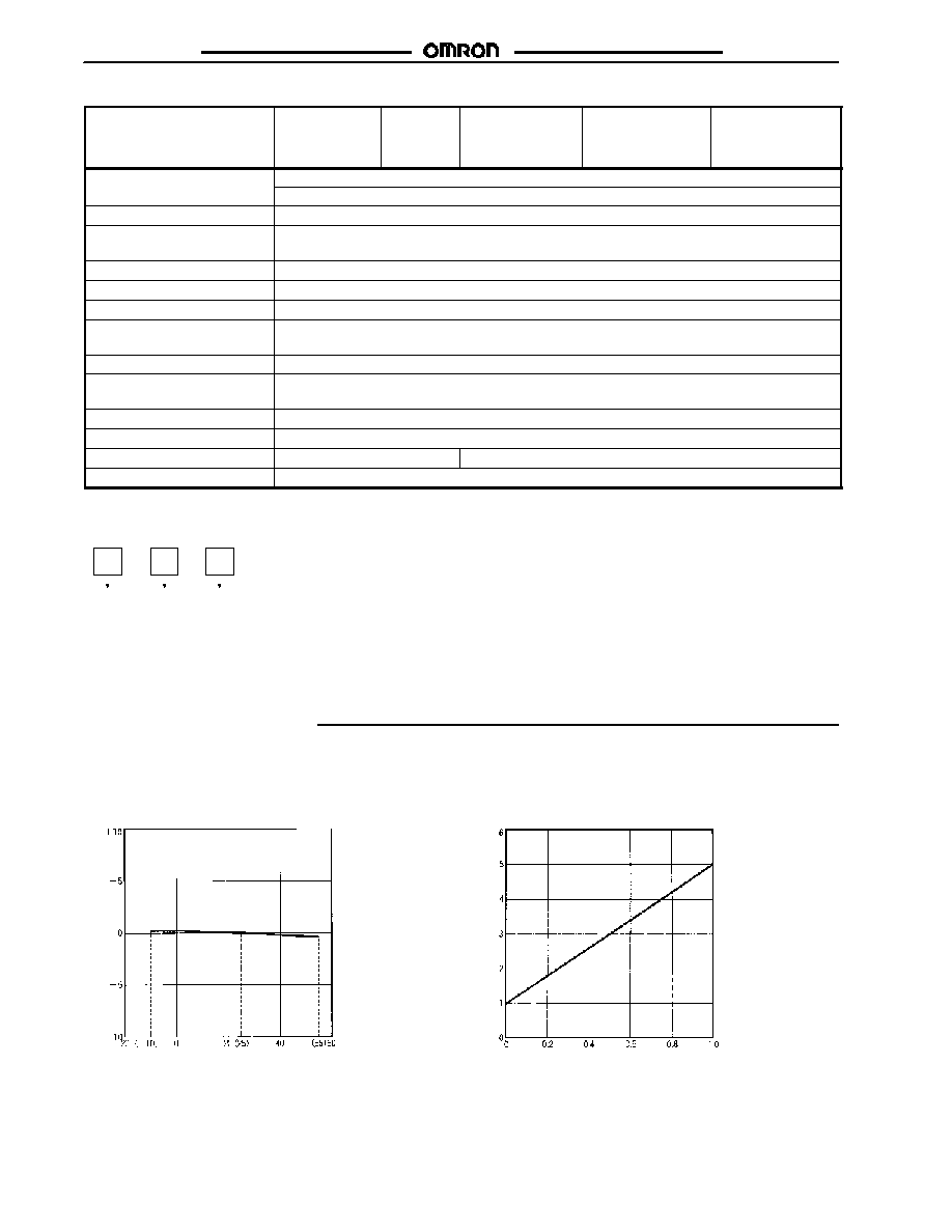
TEMPERATURE VS LINEAR OUTPUT
FLUCTUATION (TYPICAL)
J
PRESSURE VS LINEAR OUTPUT
VOLTAGE (TYPICAL)
E8CB-01C
E8CB-01C
Li
near
out
put
f
l
uc
t
uat
i
o
n
(
%
F
S
)
Li
near
out
put
v
o
l
t
age
(
V
)
Temperature (∞C)
Pressure (kgf/cm
2
)
O
per
at
i
n
g
p
r
e
s
s
u
r
e
f
l
uc
t
uat
i
o
n
(
%
F
S
)
E8CB/E8CC
E8CB/E8CC
5
J
TEMPERATURE VS OPERATING
PRESSURE (TYPICAL)
J
LINEARITY (TYPICAL)
E8CB-01C
O
per
at
i
n
g
p
r
e
s
s
u
r
e
f
l
uc
t
uat
i
o
n
(
%
F
S
)
Temperature (∞C)
E8CB-01C
Li
near
i
t
y
dev
i
a
t
i
on
(
%
F
S
)
Pressure (kgf/cm
2
)
J
VOLTAGE VS. OPERATING
PRESSURE FLUCTUATION (TYPICAL)
E8CB-01C
O
per
at
i
n
g
p
r
e
s
s
u
r
e
f
l
uc
t
uat
i
o
n
(
%
F
S
)
Voltage (V)
J
VOLTAGE VS. LINEAR OUTPUT
FLUCTUATION (TYPICAL)
E8CB-01C
Li
near
out
put
f
l
uc
t
uat
i
o
n
(
%
F
S
)
Voltage (V)
J
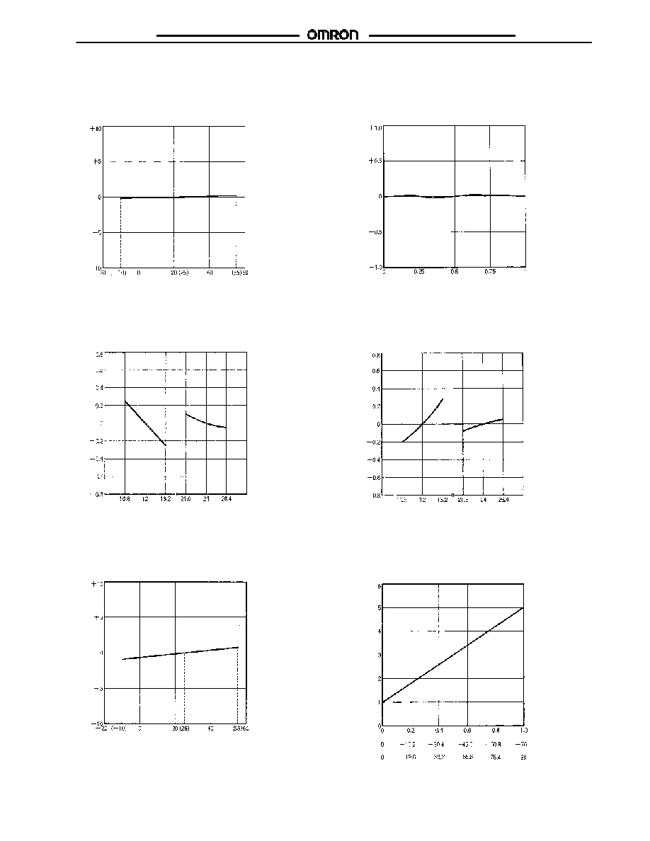
TEMPERATURE VS. LINEAR OUTPUT
FLUCTUATION (TYPICAL)
J
PRESSURE VS. LINEAR OUTPUT
VOLTAGE (TYPICAL)
E8CC-A01C
E8CC-A01C
Li
near
out
put
f
l
uc
t
uat
i
o
n
(
%
F
S
)
Temperature (∞C)
Li
near
out
put
v
o
l
t
age
(
V
)
Pressure (kgf/cm
2
)
Pressure (cmHg)
Pressure (kPa)

E8CB/E8CC
E8CB/E8CC
6
J
TEMPERATURE VS. OPERATING
PRESSURE (TYPICAL)
J
LINEARITY (TYPICAL)
Temperature (∞C)
E8CC-A01C
O
per
at
i
n
g
p
r
e
s
s
u
r
e
f
l
uc
t
uat
i
o
n
(
%
F
S
)
Li
near
i
t
y
dev
i
a
t
i
on
(
%
F
S
)
Pressure (kPa)
E8CC-A01C
Pressure (kgf/cm
2
)
J
VOLTAGE VS. OPERATING
PRESSURE FLUCTUATION
(TYPICAL)
O
per
at
i
n
g
p
r
e
s
s
u
r
e
f
l
uc
t
uat
i
o
n
(
%
F
S
)
Voltage (V)
J
VOLTAGE VS. LINEAR OUTPUT
FLUCTUATION (TYPICAL)
Li
near
out
put
f
l
uc
t
uat
i
o
n
(
%
F
S
)
Voltage (V)
E8CC-AN0C
E8CC-AN0C
E8CB/E8CC
E8CB/E8CC
7
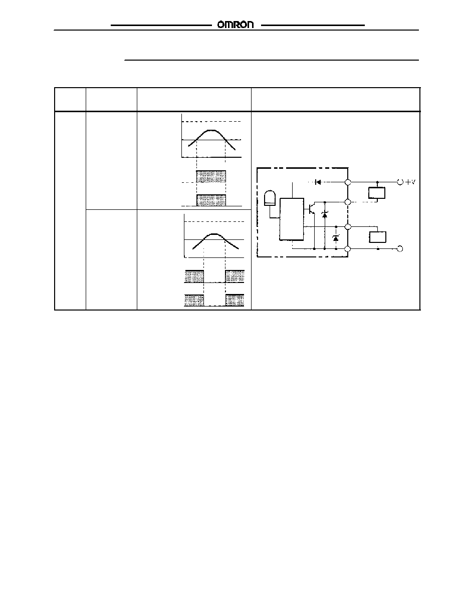
Operation
J
E8CB/E8CC PRESSURE SENSOR
Output
configu-
ration
Model
Timing Charts
Output Circuits
NPN
output
E8CB-01C,
E8CC-A01C,
E8CC-B10C
Pressure
(kgf/cm
2
)
Setting
ON
OFF
ON
OFF
Output
Indicator
0
1
Operation
indicator
M i
Brown
Load
White (ON/OFF)
E8CB-CN0C2B,
E8CC-AN0C
Pressure
(cmHg)
Setting
ON
OFF
ON
OFF
Output
Indicator
-- 76
0
Main
circuit
Load
Blue
Black (linear output)
White (ON/OFF)
0 V
E8CB/E8CC
E8CB/E8CC
8
J
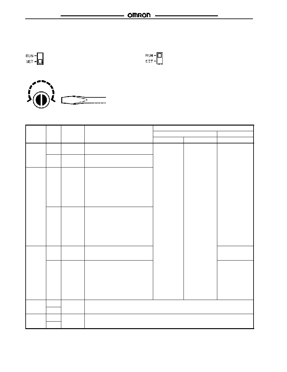
CORRECT USE
Adjustment (E8CC)
1. Set the mode selector to SET.
2. Turn the pressure adjuster to the desired pressure.
Screwdriver
0
--76
3. Set the mode selector to RUN.
The E8CC has normal output in the SET mode. Changing the
pressure setting is possible in RUN mode by turning the pressure
adjuster. Do not turn the pressure adjuster after it has been set to
the desired pressure.
Indication
Display
Mode
Operating
Description
Permissible range
Display
Mode
Operating
status
Description
Positive pressure
Negative pressure
E8CC-A01C
E8CC-B10C
E8CC-AN0C
30
RUN
Normal
Displays pressure within the
permissible range.
0 to 98 kPa
(0 to 14.2 psi)
0 to 980 kPa
(0 to 142.1 psi)
0 to --101 kPa
(0 to --14.6 psi)
30
(for
30 kPa)
SET
Normal
Displays the ON-point pressure within
the permissible range
--
RUN
Abnormal
pressure
imposition
Positive Pressure: Indicates that the
imposed pressure is lower than the
permissible range.
Negative Pressure: Indicates that the
imposed pressure is higher than the
permissible range.
The E8CC is in normal output
operation in both cases.
SET
Abnormal
pressure
setting
Positive Pressure: Indicates that
ON-point pressure value is lower than
the permissible range.
Negative Pressure: Indicates that
ON-point pressure is higher than the
permissible range.
The E8CC is in normal output
operation in both cases.
ff
RUN
Abnormal
pressure
imposition
Indicates that the imposed pressure is
higher than the permissible range.
---
SET
Abnormal
pressure
setting
Positive Pressure: Indicates that
ON-point pressure value is higher than
the permissible range.
Negative Pressure: Indicates that
ON-point pressure is lower than the
permissible range.
The E8CC is in normal output
operation in both cases.
0 to --101 kPa
(0 to --14.6 psi)
le
RUN
Load
overcurrent
Indicates that the output transistor has excessive load current. The result is that the output of the
E8CC is turned OFF This display flashes until the condition returns to normal Check the output
le
SET
overcurrent
E8CC is turned OFF. This display flashes until the condition returns to normal. Check the output
wiring if this display flashes.
5h
RUN
Element
destruction
Indicates that the Pressure Sensor element is damaged due to the imposition of excessive pressure
or for other reasons in which case the output of the E8CC turns OFF If this display appears the
5h
SET
destruction
or for other reasons, in which case the output of the E8CC turns OFF. If this display appears, the
E8CC can no longer be used.

E8CB/E8CC
E8CB/E8CC
9
Dimensions
Unit: mm (inch)
J
E8CB
Operation indicator
Pressure adjuster
36.6
(1.44)
27.4
(1.08)
Two, M4 mounting
holes
4-dia. vinyl-insulated round cable
with 4 cores; standard length: 2 m
52.5
(2.07)
40.5
(1.59)
8.5
(0.34)
19
(0.75)
25
(0.98)
26.8
(1.06)
4
(0.16)
3.75
(0.15)
3
(0.12)
12.5
(0.49)
15
(0.59)
M5 depth: 7.5
(0.30)
NPT 1/8
J
E8CC
Operation indicator
Pressure adjuster
Two, M4
mounting holes
4-dia. vinyl-insulated round cable
with 4 cores; standard length: 2 m
Display
Display mode selector
17
(0.67)
51.2
(2.01)
56.2
(2.21)
2.6
(0.10)
29.5
(1.16) 28
(1.10)
11.3
(0.44)
67
(2.64)
55
(2.17) 3.75
(0.15)
8.5
(0.34)
13.9
(0.55)
36.1
(1.42)
19
(0.75)
2
(0.08)
20.6
(0.81)
12.5
(0.49)
15
(0.59)
3
(0.12)
M5 depth: 7.5
(0.30)
NPT 1/8

E8CB/E8CC
E8CB/E8CC
10
J
MOUNTED TO A DIN-RAIL MOUNTING BRACKET
Two, M4 mounting
holes
M5 depth: 7.5
(0.30)
4-dia. vinyl-insulated round cable
with 4 cores; standard length: 2 m
DIN-rail mounting
8.5
(0.34)
6
(0.24)
28
(1.10)
29.5
(1.16)
11.3
(0.44)
2.6
(0.10)
5.5
(0.22)
15
(0.59)
56.3
(2.22)
67
(2.64)
19
(0.75)
2
55
(2.17)
18
(0.71)
3
(0.12)
1.5
(0.06)
3.75
(0.15)
NPT 1/8
Precautions
J
MOUNTING
Diaphragm
If the diaphragm is damaged, the Pressure Sensor will not
operate correctly. Do not insert a screwdriver or steel wire into
the pressure port.
The pressure port has an NPT 1/8 taper screw and M5 female
screw. Apply sealing tape around the female taper screw so that
no pressure leakage will occur.
Make sure that the tightening torque of the M5 female screw is
3.9 N S m (2.87 ft ∑ lbs) or less.
If the Pressure Sensor is directly connected to a conduit, be sure
to apply a wrench to the pressure port, not to the plastic case.
Pressure port
J
DIN-RAIL MOUNTING BRACKET (E8CC)
Mounting
∑
Fit the front part onto the bracket.
∑
Press the rear part onto the bracket.
Removing
∑
Apply a flat-blade screwdriver to the rear hook. Then the
Pressure Sensor can be removed easily.
DIN-rail mounting bracket (provided with each model)
J
WIRING
If no linear output is used, cut off the black lead wire and apply
insulation tape to the lead wire so that it will not come in contact
with any other terminal.

E8CB/E8CC
E8CB/E8CC
Cat. No. CEDSAX4 11/01 Specifications subject to change without notice. Printed in U.S.A
.
OMRON ELECTRONICS LLC
One East Commerce Drive
Schaumburg, IL 60173
NOTE: DIMENSIONS SHOWN ARE IN MILLIMETERS. To convert millimeters to inches divide by 25.4.
1-800-55-OMRON
OMRON CANADA, INC.
885 Milner Avenue
Scarborough, Ontario M1B 5V8
416-286-6465
R
OMRON ON--LINE
Global -- http://www.omron.com
USA -- http://www.omron.com/oei
Canada -- http://www.omron.com/oci