 | –≠–ª–µ–∫—Ç—Ä–æ–Ω–Ω—ã–π –∫–æ–º–ø–æ–Ω–µ–Ω—Ç: E8F2-AN0C | –°–∫–∞—á–∞—Ç—å:  PDF PDF  ZIP ZIP |
Document Outline
- First Page
- Ordering Information
- Application Examples
- Specifications
- Engineering Data
- Nomenclature
- Operation
- Dimensions
- Precautions
- Contacting Omron
2
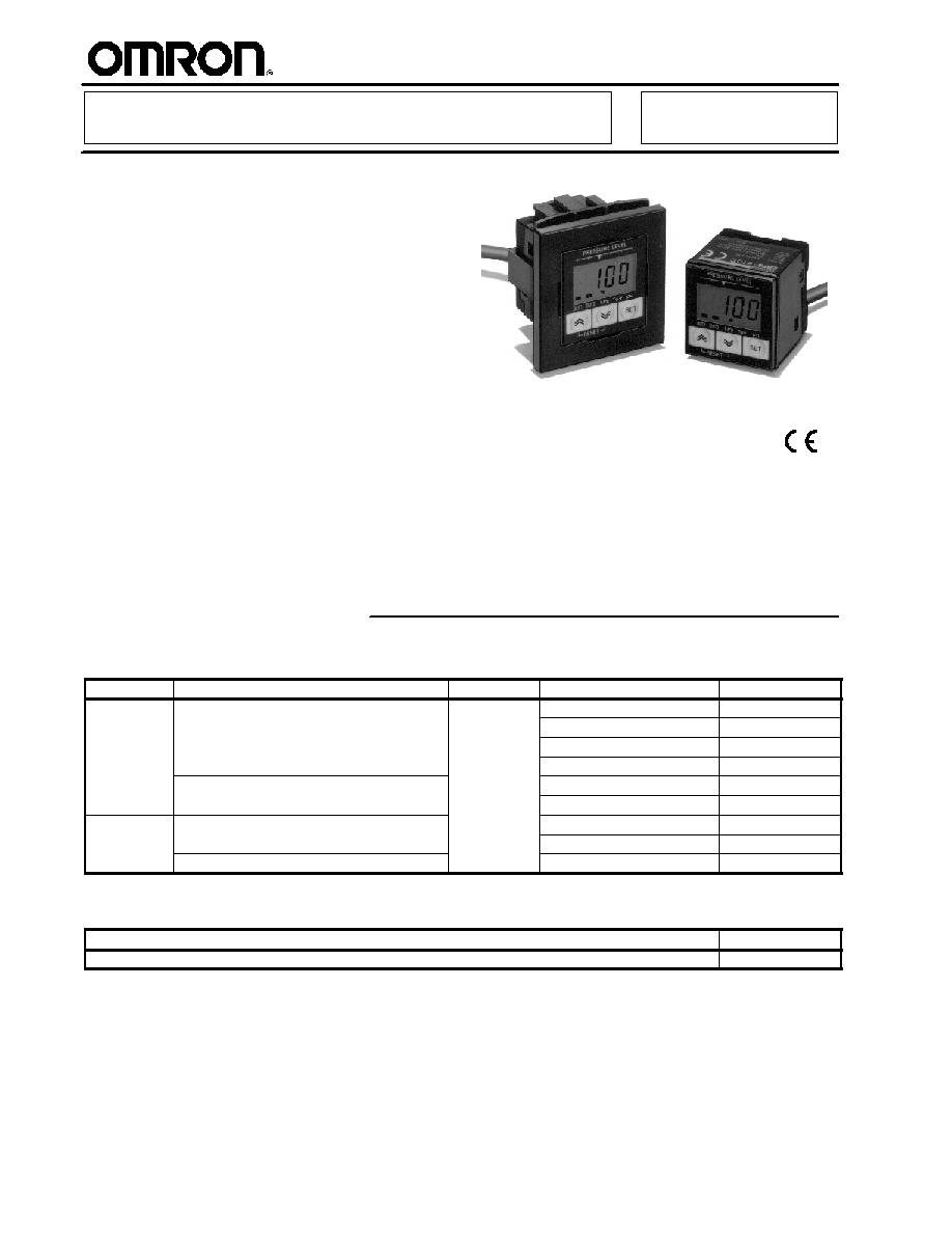
Pressure Sensor
E8F2
"Cube-Type" Pressure Sensor, with
LED Display, Offers High-Precision
Sensing
H
New psi version available
H
Compact style: 28 x 28 x 29 mm
(1.10 x 1.10 x 1.14 in) saves mounting
space
H
Easy-to-read LEDs
H
Displays both analog bar and digital
pressure values
H
Two independent discrete outputs
available--plus one analog output
H
Select either NPN and PNP output type
Ordering Information
J
SENSORS
Type
Digital output
Analog output Pressure range
Part number
Positive
NPN open collector (independent, two outputs)
1 to 5 V
0 to 100 kPa
E8F2-A01C
Positive
pressure
NPN open collector (independent, two outputs)
1 to 5 V
0 to 1 MPa
E8F2-B10C
0 to 14.5 psi
E8F2-D01C
0 to 145 psi
E8F2-D10C
PNP open collector (independent, two outputs)
0 to 100 kPa
E8F2-A01B
PNP open collector (independent, two outputs)
0 to 1 MPa
E8F2-B10B
Negative
NPN open collector (independent, two outputs)
0 to --101 kPa
E8F2-AN0C
Negative
pressure
NPN open collector (independent, two outputs)
0 to -14.6 psi
E8F2-DN0C
PNP open collector (independent, two outputs)
0 to-101 kPa
E8F2-AN0B
J
ACCESSORIES (ORDER SEPARATELY)
Description
Part number
Panel-mounting bracket
E89-F4
E8F2
E8F2
3
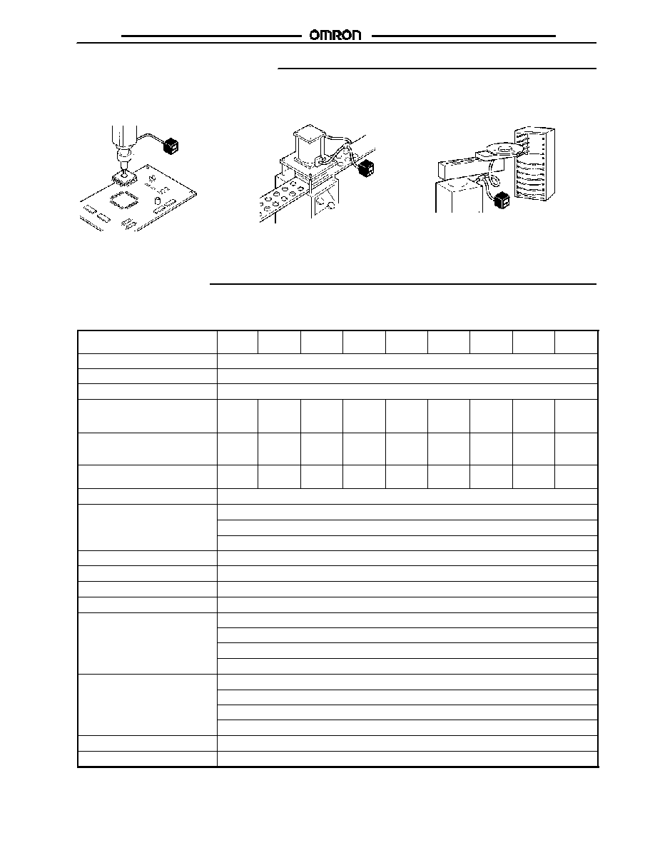
Application Examples
J
PCB AND WAFER
ATTACHMENT CHECKS
E8F2
E8F2
E8F2
J
AIR PRESSURE
CHECKS
J
CHIP ATTACHMENT
CHECKS
Specifications
J
RATINGS/CHARACTERISTICS
Item
E8F2-
A01C
E8F2-
B10C
E8F2-
AN0C
E8F2-
D01C
E8F2-
D10C
E8F2-
DN0C
E8F2-
A01B
E8F2-
B10B
E8F2-
AN0B
Power supply voltage
12 to 24 VDC ± 10% with a ripple (p-p) of 10% max.
Current consumption
70 mA max. (See Note 1.)
Pressure type
Gauge pressure
Rated pressure range
0 to 100
kPa
0 to 1
MPa
0 to
--101
kPa
0 to 14.5
psi
0 to 145
psi
0 to
--14.6
psi
0 to 100
kPa
0 to 1
MPa
0 to
--101
kPa
Pressure setting range
0 to 100
kPa
0 to 1
MPa
0 to
--101
kPa
0 to 14.5
psi
0 to 145
psi
0 to
--14.6
psi
0 to 100
kPa
0 to 1
MPa
0 to
--101
kPa
Withstand pressure
400 kPa 1.5 MPa
400 kP
58 psi
217.6
psi
58 psi
400 kPa
1.5 MPa
400 kPa
Applicable fluid
Non-corrosive gas and non-flammable gas
Operating mode(s)
Hysteresis mode
Window mode
Auto-teaching mode
Repeat accuracy (ON/OFF output)
±1% FS max.
Linearity
±1% FS max.
Response time (ON/OFF output)
5 ms max.
Linear output
1 to 5 V± 5% FS with an output impedance of 1 k and a permissible resistive load of 500 k min.
ON/OFF output
NPN open collector (NO/NC)
Load current: 30 mA max.
Output applied voltage: 30 VDC max.
Residual voltage: 1 V max. with a load current of 30 mA
Display (See Note 2.)
3.5-digit red LED
Green LED bar indicator
The orange LED is lit for two independent outputs with output transistor turned ON
Green unit indicator
Display accuracy
±3% FS ± 1 digit max.
Circuit protection
Reverse polarity connection, load short-circuiting
E8F2
E8F2
4
Item
E8F2-
A01C
E8F2-
B10C
E8F2-
AN0C
E8F2-
D01C
E8F2-
D10C
E8F2-
DN0C
E8F2-
A01B
E8F2-
B10B
E8F2-
AN0B
Temperature influence
±3% FS max.
Ambient temperature
Operating:
0∞C to 55∞C (32∞F to 131∞F)
Storage:
--10∞C to 60∞C (14∞F to 140∞F)
with no icing
Ambient humidity
Operating/Storage: 35% to 85% (with no condensation)
Voltage influence
±1.5% FS max.
Insulation resistance
100 M min. (at 500 VDC) between current-carry parts and case
Dielectric strength
1,000 VAC at 1 min
Vibration resistance
Destruction: 10 to 500 Hz, 1.0-mm double amplitude or 150 m/s
2
, 3 times each for 11 min in X,
Y,and Z directions
Shock resistance
300 m/s
2
(30G) 3 times each in X, Y, and Z directions
Degree of protection
IEC60529, IP50
Pressure port
1/8 NPT male screw and M5 female screw
Connection method
Pre-wired (standard length: 2 m)
Cable
Approved by UL
Weight (incl. packing material)
Approx. 110 g (3.88 oz)
Material
Pressure port: aluminum die cast
Case: heat-resistant ABS
Accessories
Mounting bracket
Instruction sheet
Note: 1. The current consumption is approximately 43 mA in energy-saving mode.
2. Display Example of Digital Indicator
Model
Setting unit
Model
kPa
psi
Applied
pressure
Digital display
Applied
pressure
Digital display
E8F2-A01C/E8F2-A01B
100
1
0
0
0
E8F2-B10C/E8F2-B10B
1,000
1
0
0
0
E8F2-AN0C/E8F2-AN0B
--101
--1 0
1
0
E8F2-D01C
14.5
1
4
5
0
E8F2-D10C
145
1
4
5
0
E8F2-DN0C
-14.5
-1
4
6
0
Note: The "
.
" in the display indicates the decimal point. Its position will not change unless the setting unit is changed.
E8F2
E8F2
5
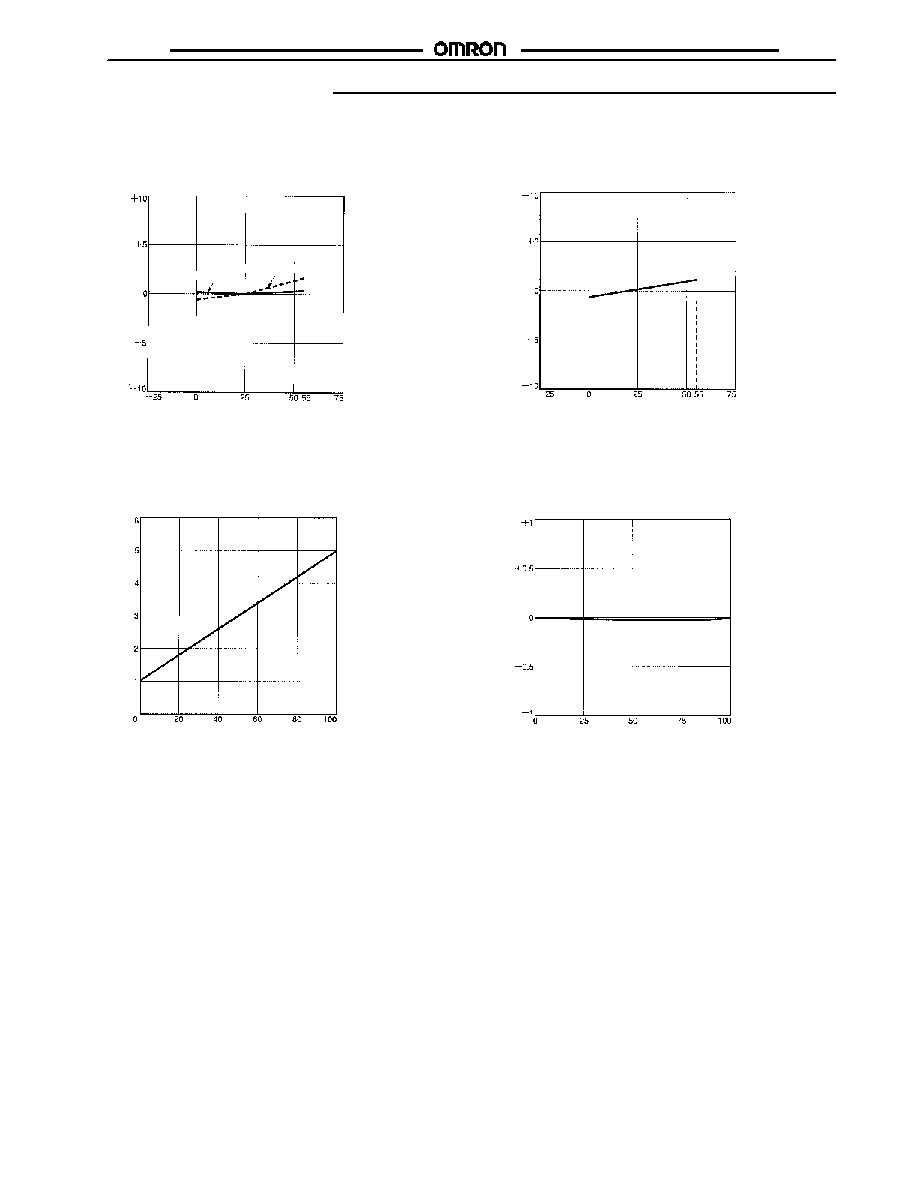
Engineering Data
J
TEMPERATURE VS. LINEAR OUTPUT
CURRENT FLUCTUATION (TYPICAL)
J
TEMPERATURE VS. OPERATING
PRESSURE FLUCTUATION (TYPICAL)
Li
near
out
put
f
l
uc
t
uat
i
o
n
(
%
F
S
)
Pressure 0
Rated pressure
Temperature (∞C)
O
per
at
i
n
g
p
r
e
s
s
u
r
e
f
l
uc
t
uat
i
o
n
(
%
F
S
)
Temperature (∞C)
E8F2-A01C
E8F2-A01C
J
PRESSURE VS. LINEAR OUTPUT
(TYPICAL)
J
LINEARITY (TYPICAL)
E8F2-A01C
E8F2-A01C
Li
near
out
put
v
o
l
t
age
(
V
)
Pressure (kPa)
Li
near
i
t
y
dev
i
a
t
i
on
(
%
F
S
)
Pressure (kPa)
E8F2
E8F2
6
Nomenclature
J
E8F2 PRESSURE SENSOR (PSI TYPE)
(1)
(4)
(5)
(2)
(3)
(8)
(7)
(6)
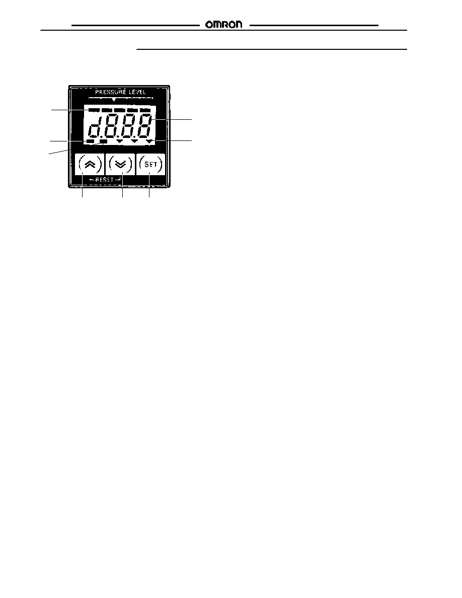
Display Panel
1. Bar indicator (green)
Indicates the degree of the measured pressure according to the the set pressure.
2. Numeric and menu display (red)
Indicates measurement values and menu setting items.
3. Unit indicator (green)
Indicates the unit used for detection; the indicator shows which unit is the one currently set.
4. OUT1 indicator (orange)
OUT1 indicator turns ON when OUT1 is turned ON.
5. OUT2 indicator (orange)
OUT2 indicator turns ON when OUT2 is turned ON.
Operation
6. Up key
7. Down key
∑
Both the Up and the Down key are used to select or change the set items, set contents, and set values in setting
mode.
∑
Press either key (Up or Down key) to check the ON and OFF points in measurement mode. The values are reset by
pressing both keys simultaneously.
∑
Use either the Up or the Down key (as necessary) together with the SET key for setting the Sensor to a special setting
mode or energy-saving mode.
8. SET key
∑
Used for entering the set contents and set values in setting mode.
∑
Used for setting the Sensor to basic setting mode or pressure setting mode.
kPa Torr Psi
OUT1 OUT2

E8F2
E8F2
7
Operation
J
OUTPUT STAGE CIRCUIT
Output type
NPN output (normally open)
NPN output (normally closed)
Model
E8F2-A01C
E8F2-B10C
E8F2-AN0C
Timing
chart
Hysteresis
mode
Pressure
ON point
OFF point
Output
OUT
indicator
(orange) OFF
ON
OFF
ON
Pressure
ON point
OFF point
Output
OUT
indicator
(orange) OFF
ON
Window
mode
Pressure
OFF point
ON point
Output
OUT
indicator
(orange)
OFF
ON
OFF point -- 10% FS
max.
ON point -- 10% FS
max.
OFF
ON
Pressure
OFF point
ON point
Output
OUT
indicator
(orange) OFF
ON
OFF point -- 10% FS
max.
ON point -- 10% FS
max.
Output circuit
Pressure
Sensor
main
circuit
Brown
Black
(ON/OFF1)
30 mA
max.
Load
30 mA
max.
White (ON/OFF2)
Gray
(linear)
1 to 5 V
Load
Blue
0 V
12 to 24 V
Load
E8F2
E8F2
8
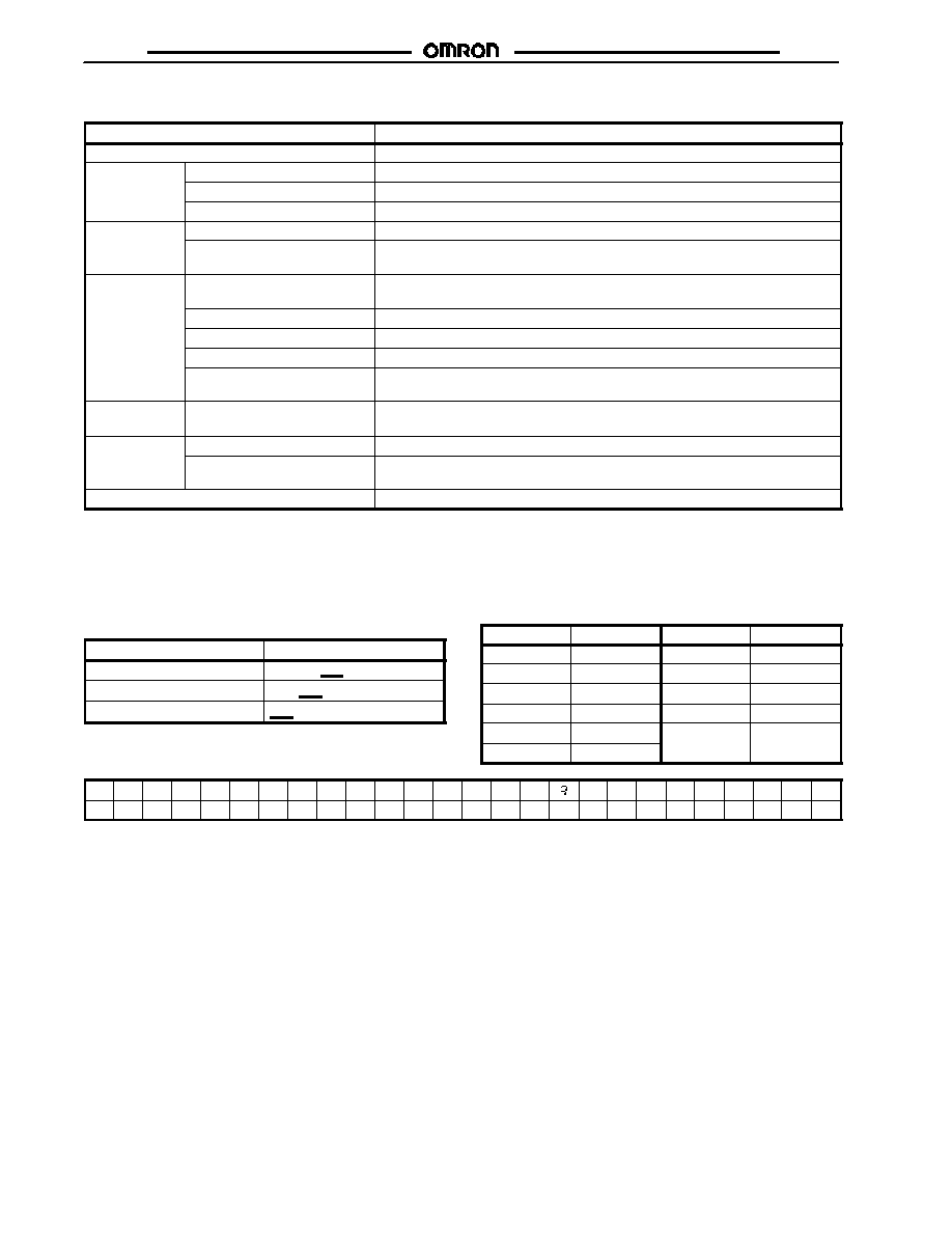
J
FUNCTIONS AND SETTINGS
Function/Setting
Description
Zero-reset function
Sets the measurement value to 0 when the Sensor is exposed to the air.
Basic setting
Unit setting
Changes the unit for detection.
Basic setting
mode
Pressure setting method
---
Output-type setting
Selects normally-open or normally-closed output.
Pressure
Manual setting
Sets the ON and OFF points manually.
Pressure
setting mode
Auto-teaching setting
Automatically sets the ON and OFF points depending upon the actual sensing of
objects.
Special setting
mode
Key-protect setting
Protects the set value against the incorrect operation of the keys.
Prevents the set value against the careless operation of the keys.
Hysteresis width setting
Changes the hysteresis range.
Window range setting
Changes the window mode setting.
Display refresh interval setting
Changes the display refresh interval to make the displayed value easier to see.
Measurement value averaging
time setting
Prevents incorrect output due to sudden, instantaneous changes that may occur
with pressure.
Special setting
mode
LED bar indicator range setting
Changes the display range of the LED bar indicator in hysteresis mode.
Energy-saving
Energy-saving function 1
Displays the LED bar indicator but turns the red LED display OFF.
Energy saving
mode
Energy-saving function 2
The LED bar indicator and red LED display flash in window mode if the measured
value exceeds the set range.
ON/OFF set value check function
Checks the set ON and OFF points.
J
SETTINGS
Digital Display
The E8F2 displays alphanumeric characters, such as the
measurement values and menu items, with 7-segment LEDs.
Refer to the examples shown below.
Display
Meaning
ope
In output operation
kpa
Unit (kPa)
wid
Width
The following abbreviations are used for the digital display of the
Controller.
Abbreviation
Meaning
Abbreviation
Meaning
Unt
Unit
DSP
Display
M-A
Manual/Auto
AVE
Average
OPE
Operation
BAR
Bar
PRT
Protect
AUT
Auto
HYS
Hysteresis
ECO
Economy
WID
Width
a
b
c
d
e
f
g
h
i
j
k
l
m
n
o
p
r
s
t
u
U
w
x
y
=
A
B
C
D
E
F
G
H
I
J
K
L
M
N
O
P
Q
R
S
T
U
V
W
X
Y
Z
E8F2
E8F2
9
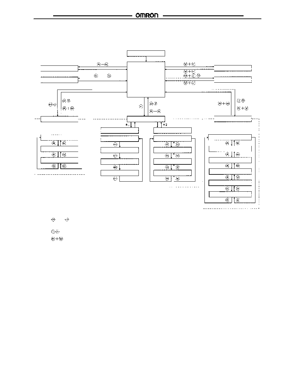
J
MODES
In addition to displaying measurement values, the E8F2 has a variety of functions. These functions are available in four main modes as
described below: Measurement Mode, Basic Setting Mode, Pressure Setting Mode, Special Setting Mode. Three functions are available
in measurement mode. For the relationships among each mode and for switching methods, refer to the following figure.
Power ON
Zero-reset function
ON- and OFF-point
check function
No key operation
No key operation
Measurement
Mode
Energy-saving function 1
Energy-saving function 2
or
or
Basic Setting Mode
unt
: Measurement unit selection
m-a
: Pressure setting method
selection
ope
: Output-type selection
Pressure Setting Mode
on
: OUT1 ON-point setting
off
: OUT1 OFF-point setting
Manual setting
on
: OUT2 ON-point setting
off
: OUT2 OFF-point setting
t
.h1: OUT1 two-point teaching
t
.w: OUT1 one-point teaching
Auto-teaching setting
t
.h1: OUT2 two-point teaching
t
.w: OUT2 one-point teaching
prt
: Key-protect setting
Special Setting Mode
hys
: Hysteresis width setting
wid
: Window width setting
dsp
: Measurement value display
refresh interval setting
aUe
: Number of measurement times
setting for measurement value averaging
bar
: LED bar indicator range setting
or
or
Note: 1.
and
indicate that the key must be pressed for approximately 2 or 3 s respectively.
2. The following will result when the E8F2 in basic, pressure setting, or special setting mode is reset to measurement mode.
:
The set values are entered.
: The set values are not entered (left as they are).
*1.Manual setting is available by selecting m (manual) in the pressure setting method selection in basic setting mode.
*2.Auto-teaching setting is available by selecting a (auto-teaching) in the pressure setting method selection in basic setting mode.
E8F2
E8F2
10
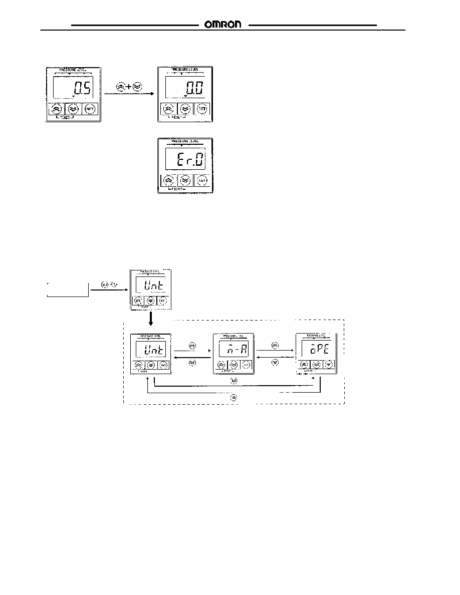
Measurement mode
Normal
Error
OUT1 OUT2 kPa Torr Psi
OUT1 OUT2 kPa Torr Psi
OUT1 OUT2 kPa Torr Psi
The displayed measurement value is reset to 0 by pressing the Up and Down keys simultaneously. The reset range is within ±5% (FS)
of the rated pressure. If the value is not within the range, an error will be displayed and the reset will not be enabled.
Use the zero-reset function with the Sensor exposed to the air.
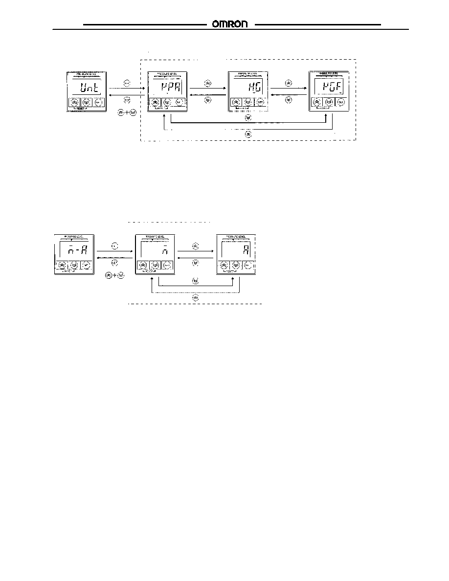
Basic Setting Mode
The unit of measurement, pressure setting method, and output type are set in basic setting mode.
1. Press the SET key for approximately 2 s so that the E8F2 will be set to basic setting mode and unt will be displayed.
2. Set the items unt, m--a, and ope with Up or Down key.
Measurement
mode
Setting item
Setting item
Unit setting
Pressure setting method selection
Output-type setting
OUT1
OUT2
kPa Torr Psi
OUT
1
OUT
2
kPa Torr Psi
kPa Torr Psi
OUT1 OUT2
kPa Torr Psi
Zero-reset Function
OUT1 OUT2
kPa Torr Psi
E8F2
E8F2
11
1. Press the SET key while unt is displayed to display the unit presently set.
2. Press the Up or Down key to select the unit.
3. Press the SET key to select the displayed unit and display unt again.
4. Press the Up and Down keys simultaneously, to display unt again without selecting the unit.
Unit Setting
Unit setting in E8F2-AN0C
OUT1 OUT2 kPa Torr Psi
OUT1 OUT2 kPa Torr Psi
OUT1 OUT2 kPa Torr Psi
OUT1 OUT2 kPa Torr Psi
kPa
Pressure Setting Method Selection
Setting item
Pressure setting
Manual setting
Auto-teaching
m
: Manual setting (The ON and
OFF points are manually set.)
a
: Auto-teaching (The ON and OFF
points are set automatically.)
or
OUT1 OUT2 kPa Torr Psi
OUT1 OUT2 kPa Torr Psi
OUT1 OUT2 kPa Torr Psi
1. Press the SET key while m--a is displayed to display the pressure setting method presently set.
2. Press the Up or Down key to select the pressure setting method.
3. Press the SET key to select the displayed pressure setting method and display m--a again.
4. Press the Up and Down keys simultaneously to display m--a without selecting the unit.
E8F2
E8F2
12
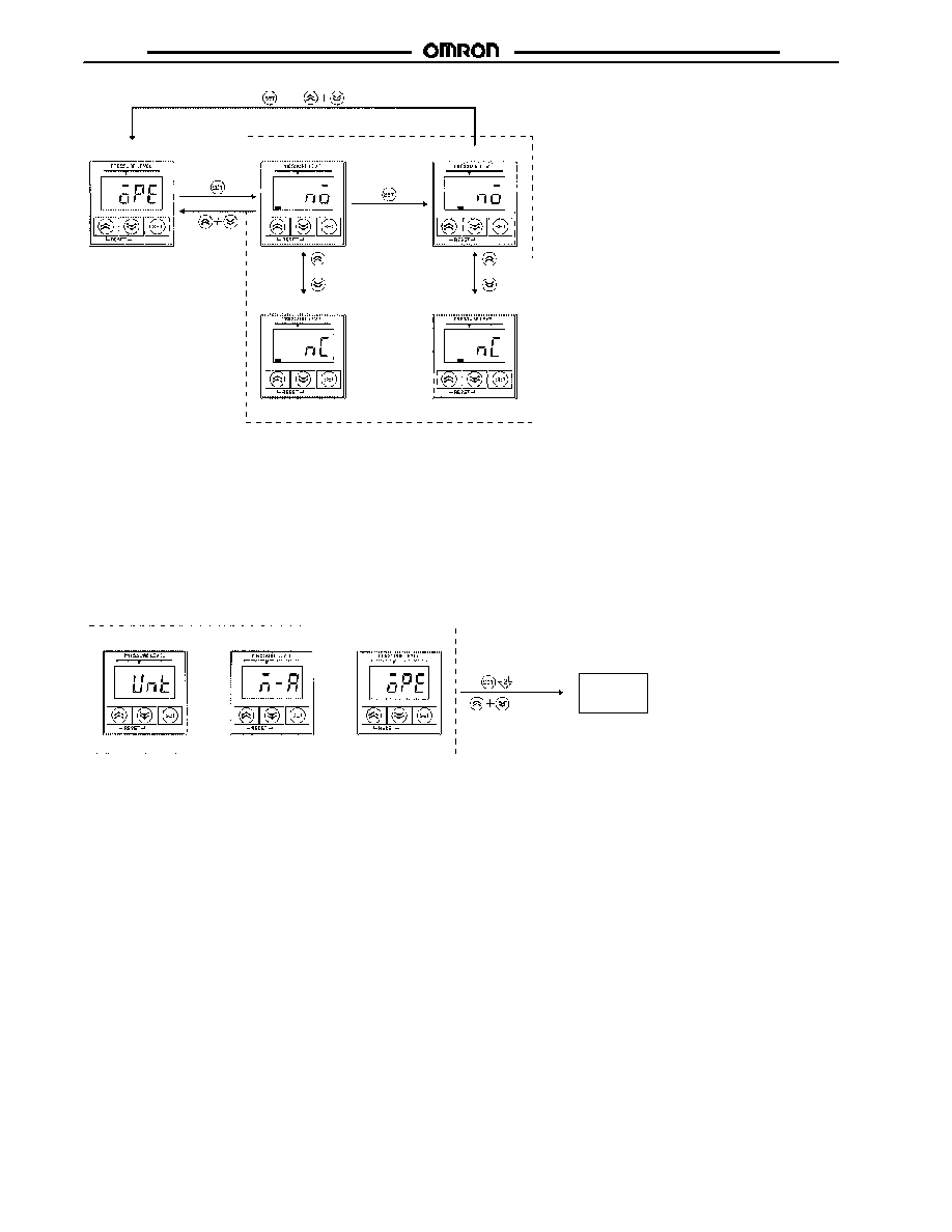
Setting item
Output-type setting
or
or
or
nc
: Normally closed
no
: Normally open
OUT1 OUT2 kPa Torr Psi
OUT1 OUT2 kPa Torr Psi
OUT1 OUT2 kPa Torr Psi
OUT1 OUT2 kPa Torr Psi
OUT1 OUT2 kPa Torr Psi
Output-Type Setting
1. Press the SET key while ope is displayed to display the output type of OUT1 presently set.
2. Press the Up or Down key to select the output type.
3. Press the SET key to select the displayed output type and display the output type of OUT2 presently set.
4. Press the Up or Down key to select the output type.
5. Press the SET key to select the displayed output type and display ope again.
6. Press the Up and Down keys simultaneously to display ope again without selecting the unit.
OUT1 N.O
OUT2 N.O
OUT1 N.C
OUT2 N.C
Setting item
Unit setting
Pressure setting
∑
Entering the Setting Item:
Press the SET key for approximately 2 s to enter the item that has been set.
or
Output configuration
or
Entered
Not entered
Measurement
mode
∑
Not Entering the Setting Item:
Press the Up and Down keys simultaneously so that the item set will not be entered.
OUT1 OUT2 kPa Torr Psi
OUT1 OUT2 kPa Torr Psi
OUT1 OUT2 kPa Torr Psi
Returning to Measurement Mode
E8F2
E8F2
13
Hysteresis mode
Window mode
OFF-point
set value
ON
OFF
ON-point
set value
Pressure
value
ON-point
set value
OFF-point
set value
Pressure
value
Normally Closed
Hysteresis mode
Window mode
OFF-point
set value
ON-point
set value
Pressure
value
ON-point
set value
OFF-point
set value
Pressure
value
Ou
tp
u
t
ON
OFF
Ou
tp
u
t
ON
OFF
Ou
tp
u
t
ON
OFF
Ou
tp
u
t
Normally Open
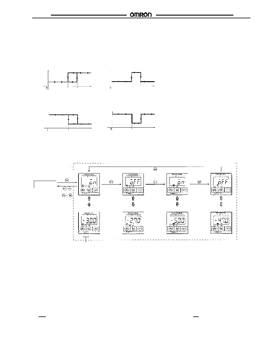
Pressure Setting Mode
The E8F2 provides output according to the measured values to control external devices, such as valves and pumps. In order to control
the external devices, a reference value can be set so that the output will be ON or OFF if the measured values are above or below the
reference value. The output ON- and OFF-point settings are described below, provided that the output is normally open.
Note: The ON and OFF points are set in pressure setting mode manually or through auto-teaching.
Manual Setting
Note: Manual setting will be possible if m is selected in pressure setting method selection in basic setting mode.
Measurement
mode
Manual setting
or
Displayed
alternately
Displayed
alternately
Displayed
alternately
Displayed
alternately
Press the Up or Down key
to change the set value.
Torr Psi
Torr Psi
Torr Psi
Torr Psi
Torr Psi
Torr Psi
Torr Psi
Torr Psi
OUT1 ON
OUT1 OFF
OUT12 ON
OUT12 OFF
1. Press the SET key, to set the E8F2 to pressure setting mode and display the OUT1 ON point and on alternately.
2. Press the Up or Down key to change the OUT1 ON point.
3. Press the SET key to select the ON point and display the OUT1 OFF point and off alternately.
4. Press the Up or Down key to change the OUT1 OFF point.
5. Press the SET key to select the displayed OFF point and display the OUT2 ON point and on alternately.
6. Press the Up or Down key to change the OUT2 ON point.
7. Press the SET key to select the ON point and display the OUT2 OFF point and off alternately.
8. Press the Up or Down key to change the OUT2 OFF point.
9. Press the SET key to select the OFF point and display the OUT1 ON point and on alternately.
Returning to Measurement Mode
∑
Entering the Setting Item: Press the SET key for approximately 2 s to enter any item that has been "set."
∑
Not Entering the Setting Item: Press the Up and Down keys simultaneously, so any item "set" will not be entered.
E8F2
E8F2
14
One-point teaching
Pressure
value
Two-point teaching
Pressure
value
ON
OFF
Ou
tp
u
t
ON
OFF
Ou
tp
u
t
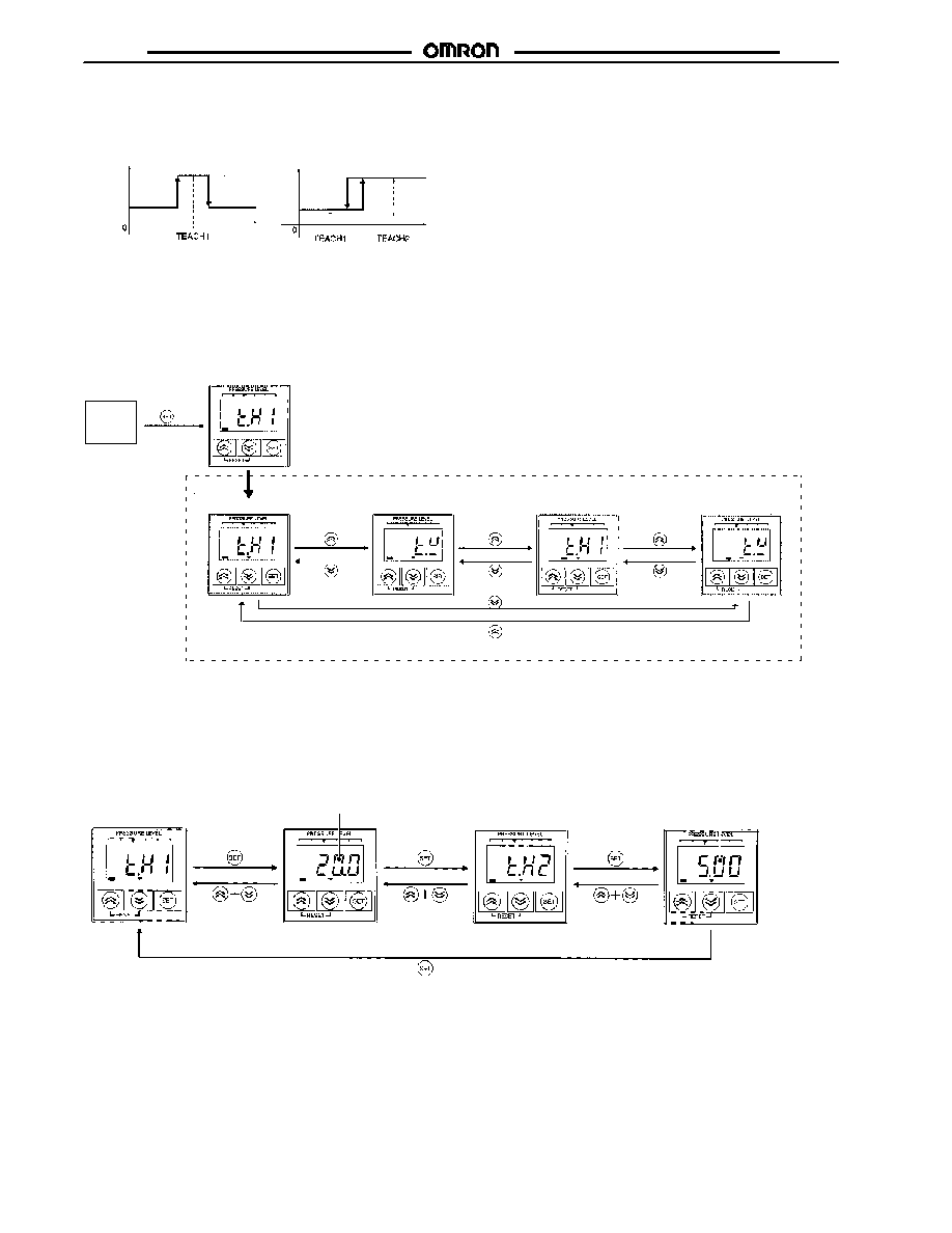
Note: Auto-teaching will be possible if a is selected in the pressure setting method selection in basic setting mode.
Auto-teaching
Auto-teaching allows input measured values to be input as ON- and OFF-point set values instead of key input. One- or two-point auto-
teaching can be selected.
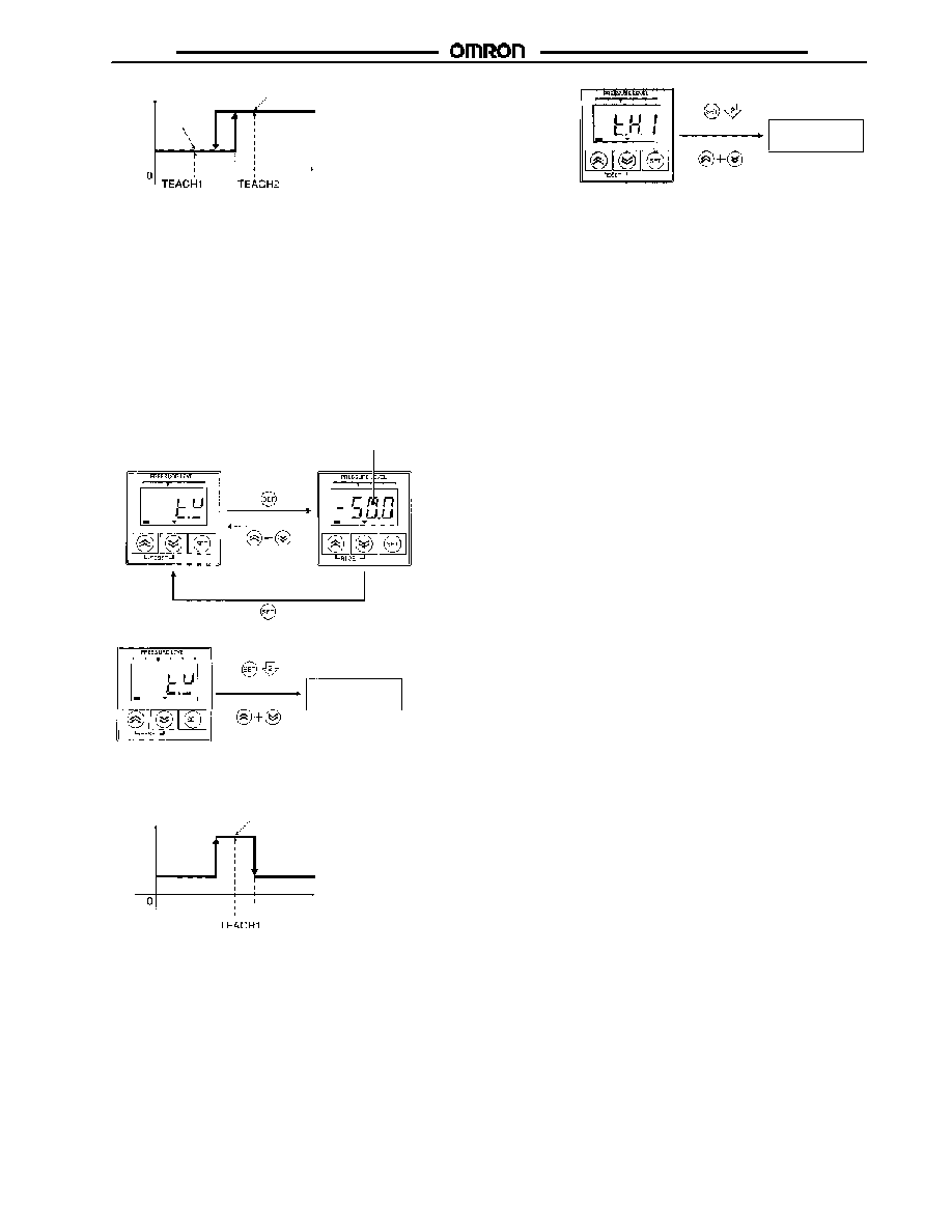
1. Press the SET key to set the E8F2 to pressure setting mode and to display OUT1 and t.h1.
2. Press the Up or Down key to select the one-point teaching or two-point teaching method of OUT1 and OUT2.
Setting item
Auto-teaching
OUT1 two-point teaching
OUT1 one-point teaching
OUT2 two-point teaching
OUT2 one-point teaching
t
.h1: Teach hysteresis mode at first point
t
.w: Teach window mode
OUT1 OUT2kPa Torr Psi
OUT1 OUT2kPa Torr Psi
OUT1 OUT2kPa Torr Psi
Measurement
mode
OUT1 OUT2 kPa Torr Psi
OUT1 OUT2 kPa Torr Psi
Two-point Teaching (Hysteresis-mode Teaching)
Present measurement
value is displayed.
Present measurement
value is displayed.
OUT1 OUT2 kPa Torr Psi
OUT1
OUT1 OUT2 kPa Torr Psi
OUT1 OUT2 kPa Torr Psi
OUT1 OUT2 kPa Torr Psi
1. Press the SET key under condition 1 below while t.h1 is displayed to display the present measurement value.
2. Check the measurement value and press the Set key to perform and complete teaching the first point.
3. Press the Set key under condition 2 below to display the present measurement value.
(This list of steps continues on the next page.)
E8F2
E8F2
15
Condition 1
Two-point Teaching
Condition 2
OFF point
ON point
Pressure value
TEACH1 and TEACH2 can
be performed in reverse
order. TEACH1 value can
be larger than TEACH2
value or vice versa.
ON
OFF
Ou
tp
u
t
Not entered
Measurement mode
Entered
or
4. Check the measurement value and press the Set key to perform and complete teaching the second point.
5. Press the SET key for approximately 2 s while t.h1 is displayed to enter the values and return the E8F2 to measurement mode.
6. Press the Up and Down keys simultaneously to set the E8F2 to measurement mode without selecting the values.
Note: The E8F2 will be automatically set to hysteresis mode by performing two-point teaching.
ON point:
(TEACH1 + TEACH2)/2
OFF point: ON point -- 3% FS
(default value) the default
value is changeable.
Two-point teaching is ideal for applications that check for vacuum attachment.
OUT1 OUT2 kPa Torr Psi
Auto-teaching
∑
One-point Teaching (Window-mode Teaching) OUT1
Present value
Measurement mode
Not entered
Entered
or
OUT1 OUT2 kPa Torr Psi
OUT1 OUT2
kPa Torr Psi
OUT1 OUT2 kPa Torr Psi
1. Press the SET key under condition 3 below while t.w is displayed to display the present measurement value.
One-Point Teaching
Condition 3
ON point
OFF point
Pressure
value
ON point: TEACH1 -- 30% FS
OFF point: TEACH1 + 30% FS
The default value is 10% FS
(changeable).
ON
OFF
Ou
tp
u
t
2. Check the measurement value and press the Set key to perform and complete teaching.
3. The values are entered Press the SET key for approximately 2 s while t.w is displayed to enter the values and return the E8F2 to
measurement mode.
4. Press the Up and Down keys simultaneously to return the E8F2 to measurement mode without selecting the values.
Note: The E8F2 will be automatically set to window mode by performing one-point teaching. One-point teaching is ideal for applications
that check original pressure.
E8F2
E8F2
16
∑
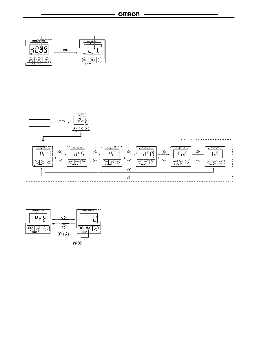
Teaching Error
Present value not
within set range
Meaning of display: er.t (Error teach)
Error display for 1 s
OUT1 OUT2 kPa Torr Psi
OUT1 OUT2 kPa Torr Psi
If the present value or the result of calculation after teaching is not within the range, the SET key input will not be accepted. In this case
an error will be displayed for 1 s if teaching is performed.
Measurement
mode
Setting item
Setting item
key-protect
Hysteresis width
Window width
Display refresh interval
Number of measurement
times for averaging
Bar indicator range
Special Setting Mode
Key-protect, hysteresis width, window width, display refresh interval, number of measurement times for averaging, and bar indicator
range settings are set in special setting mode.
1. Press the SET key and Up key simultaneously to set the E8F2 to special setting mode and display prt.
2. Set the Up or Down key to select the items prt, hys, wid, dsp, aUe, and bar.
OUT1 OUT2
kPa Torr Psi
OUT1 OUT2
kPa Torr Psi
OUT1 OUT2
kPa Torr Psi
OUT1 OUT2 kPa Torr Psi
OUT1 OUT2 kPa Torr Psi
OUT1 OUT2
kPa Torr Psi
OUT1 OUT2
kPa Torr Psi
No key-protect
or
Press the Up or Down key to
change the set value.
Key-protect Status
0: No Key-Protect.
1: No basic or pressure settings are accepted.
2: No input is accepted other than for checking the pressure value or special settings or setting to energy-saving mode.
1. Press the SET key while prt is displayed to display the key-protect value presently set.
2. Press the Up or Down key to change the value.
3. Press the SET key to select the displayed value and display prt again.
4. Press the Up and Down keys simultaneously display prt again without selecting the value.
Key-protect Setting
OUT1 OUT2
kPa Torr Psi
OUT1 OUT2
kPa Torr Psi
E8F2
E8F2
17
or
Press the Up or
Down Key to
change the set
value.
Hysteresis mode
OFF
point
ON
point
Pressure
value
Window mode
Change in
hysteresis width
desired
OFF
point
ON
point
Pressure
value
ON
OFF
Ou
tp
u
t
ON
OFF
Ou
tp
u
t
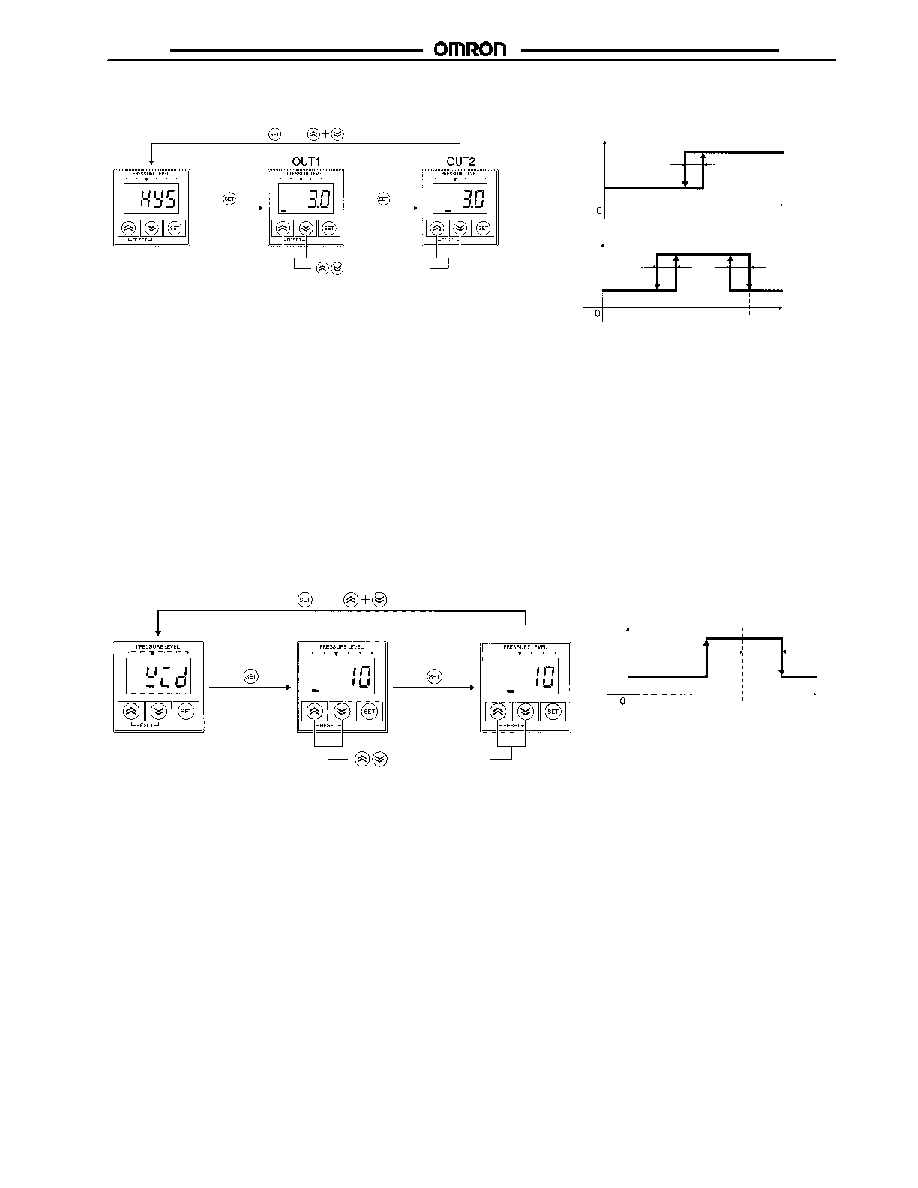
Hysteresis Width Setting
The hysteresis width can be changed by taking the following steps.
1. Press the SET key while hys is displayed to display the hysteresis width of OUT1 presently set.
2. Press the Up or Down key to change the set value within a range between 0 and 10.0% FS.
3. Press the SET key to select the displayed set value and display the hysteresis width of OUT2 presently set.
4. Press the Up or Down key to change the set value.
5. Press the SET key to select the displayed set value and display hys again.
6. Press the Up and Down keys simultaneously to display hys again without selecting the value.
Note: 1. Hysteresis Mode: No manual hysteresis width settings are enabled in hysteresis mode except for those set by auto-teaching.
Window Mode
Hysteresis width settings are enabled when the E8F2 in window mode is set to measurement mode.
2. ON- and OFF-point widths in hysteresis mode are used as hysteresis widths, which cannot be changed in window mode.
OUT1 OUT2 kPa Torr Psi
OUT1 OUT2 kPa Torr Psi
OUT1 OUT2 kPa Torr Psi
Change in
hysteresis width
desired
or
Press Up or Down key
to change set value.
(0 to 30%)
Reference value
(TEACH1)
Pressure
value
ON
OFF
Ou
tp
u
t
OUT1 OUT2 kPa Torr Psi
OUT1 OUT2 kPa Torr Psi
Window Range Setting
1. Press the SET key while wid is displayed to display the window width of OUT1 presently set.
2. Press the Up or Down key to change the set value within a range between 0 and 30% FS of the reference value.
3. Press the SET key to select the displayed set value and display the window width of OUT2 presently set.
4. Press the Up or Down key to change the set value.
5. Press the SET key to select the displayed set value and display wid again.
6. Press the Up and Down keys simultaneously to display wid again without selecting the set value.
Note: No window width settings will be enabled in hysteresis mode.
OUT1 OUT2
kPa Torr Psi
OUT1
OUT2
E8F2
E8F2
18
or
Press Up or Down key to
change set value.
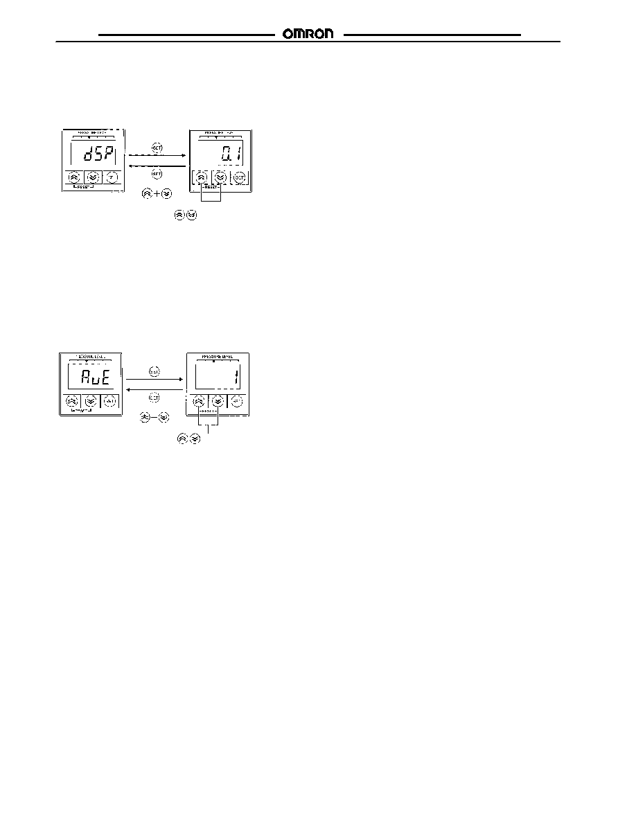
Display Refresh Interval Setting
∑
The following refresh intervals are selectable.
0.1: The average value is displayed at 0.1-s intervals.
0.5: The average value is displayed at 0.5-s intervals.
1.0: The average value is displayed at 1.0-s intervals.
1. Press the SET key while dsp is displayed to display the display refresh interval presently set.
2. Press the Up or Down key to change the set value.
3. Press the SET key to select the displayed set value and display dsp again.
4. Press the Up and Down keys simultaneously to display dsp again without selecting the set value.
Note: Set the AVE to the number of measurements for obtaining an average value.
OUT1 OUT2
kPa Torr Psi
OUT1 OUT2
kPa Torr Psi
or
Press Up or Down Key to
change set value.
OUT1 OUT2 kPa Torr Psi
OUT1 OUT2 kPa Torr Psi
Measurement Value Averaging Time Setting
The number of measurements can be set to 1, 8, 32, or 256.
1. Press the SET key while aUe is displayed to display the set value as the number of measurements for averaging measured values.
2. Press the Up or Down key to change the set value.
3. Press the SET key to select the displayed set value and display aUe again.
4. Press the Up and Down keys simultaneously to display aUe again without selecting the set value.
Note: If the DSP item is set to 0.5 and AVE item is set to 32, the E8F2 will measure 32 times, the average value of which will be treated
as one block. The average block value for 0.5 s will be displayed at 0.5-s intervals.
E8F2
E8F2
19
or
Press Up or Down key to
change set value.
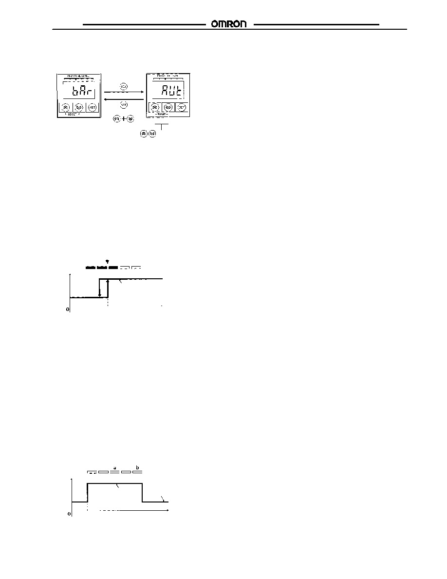
Bar Indicator Range Setting
The set value is an indication range per LED between 1 and 20% FS. If the E8F2 is set to AUT, the ideal display range will be automatica
set according to the the ON point presently set.
1. Press the SET key while bar is displayed to display the bar display range presently set.
2. Press the Up or Down key to change the set value.
3. Press the SET key to select the displayed set value and display bar again.
4. Press the Up and Down keys simultaneously to display bar again without selecting the set value.
Note: The bar indicator range will be available to OUT1 output and will be enabled in hysteresis mode only.
OUT1 OUT2 kPa Torr Psi
OUT1 OUT2 kPa Torr Psi
1-MPa Model (with 300 kPa as ON Point)
Condition 1 (350 kPa)
300
(ON point)
Pressure
value: kPa
The indication range per LED is obtained from the following.
∑
300 kPa 1 MPa x 1/2
∑
300 kPa x 1/3 = 100 kPa
ON
OFF
Ou
tp
u
t
Bar Indicator
The user can visually sense the measured pressure according to the ON and OFF points from the bar indicator. This indicator is avail-
able to OUT1 output only. There is a difference in indication mode between hysteresis mode and window mode.
∑
Hysteresis Mode
The five LEDs indicate the present pressure provided that the ON point is between the second and third LEDs from the left.
1-MPa Model
(with 300 kPa as ON point and 600 kPa as OFF point)
Condition 2
(450 kPa)
300 kPa
(ON point)
Pressure
value: kPa
Condition 3
(700 kPa)
600 kPa
(OFF point)
ON
OFF
Ou
tp
u
t
Only LED (a) will be lit under condition 2.
Only LED (b) will be lit under condition 3.
The display range per LED will be the following.
Difference between ON and OFF points x 1/5
Note: No bar indicator settings in special setting mode will be enabled
The first through third LEDs from the left are all ON under condition 1. The indication range per LED is the set value of the indication
range in special setting mode. If the set value is aut, the following ranges are obtainable.
When ON point Rated pressure x 1/2
Indication range per LED = ON point x 1/3
When ON point > Rated pressure x 1/2
Indication range per LED = (Rated value -- ON point) x 1/3
∑
Window Mode
The distance between ON and OFF points are divided into five equal portions. The present pressure will be indicated by a single
LED that will be ON. The left LED will flash if the present pressure is below the ON point and the right LED will flash if the present
pressure is above the OFF point.

E8F2
E8F2
20
Setting items
Key-protect
Hysteresis width
Window width
Display refresh
interval
Number of measurement
times for averaging
Bar indicator
range setting
Entered
Not entered
Entering Set Values:
Press the SET key for approximately 2 s
while the value is displayed.
Not Entering Set Values:
Press the Up and Down keys
simultaneously while the value
is displayed.
Measurement
mode
Returning to Measurement Mode
or
or
or
or
or
OUT1 OUT2 kPa Torr Psi
OUT1 OUT2 kPa Torr Psi
OUT1 OUT2 kPa Torr Psi
OUT1 OUT2 kPa Torr Psi
OUT1 OUT2 kPa Torr Psi
OUT1 OUT2 kPa Torr Psi
Normal Measurement Mode
OUT1 OUT2
kPa Torr Psi
OUT1 OUT2
kPa Torr Psi
Energy-saving Mode
The E8F2 has functions to save power by turning OFF the numeric and menu display and leaving the bar indicator turned ON.
Energy-saving Function 1
1. The numeric and menu display is turned OFF by pressing the SET and Down keys simultaneously in measurement mode.
2. The display is turned ON by pressing the SET and Down keys simultaneously again.
Displayed for 1 s
Pressure beyond
the set range is
imposed.
Pressure value flashes.
OUT1 OUT2
kPa Torr Psi
OUT1 OUT2 kPa Torr Psi
OUT1 OUT2
kPa Torr Psi
Energy-saving Function 2
If the present pressure is not within the set range, the numeric and menu display will flash as a warning.
1. If the SET and Down keys are pressed simultaneously for approximately 3 s in measurement mode, eco will be displayed for 1 s
and then the numeric and menu display will be turned OFF.
2. Provided that the E8F2 is set to window mode, the numeric and menu display will flash together with the bar indicator if the
present pressure is below ON point or above the OFF point.
3. The numeric and menu display and the bar indicator return to normal condition by pressing the SET and Down keys
simultaneously.
kPa Torr Psi
OUT1 OUT2

E8F2
E8F2
21
ON- and OFF Set Value Check Function
Measurement
mode
ON- and OFF-point Set value
or
or
Displayed
alternately
or
Displayed
alternately
or
Displayed
alternately
or
Displayed
alternately
OUT1 ON point
OUT1 OFF point
OUT2 ON point
OUT2 OFF point
The ON and OFF points presently set can be checked.
Press the Up or Down Key in measurement mode to display the OUT1 ON point and on alternately.
Press the Up or Down Key again to display the OUT1 OFF point and off alternately.
Press the Up or Down Key after the above to display the OUT2 items.
If no key is input for approximately 2 s during the above operation, the present measurement value will be displayed automatically.
Dimensions
Unit: mm (inch)
J
CONTROLLER
E8F2
1.5
(0.06)
Display panel
Pressure-introducing
section
Vinyl-insulated round cable with five
conductors, 4 dia. (0.08 dia. x 30);
standard length: 2 m
Two-M3 (Depth: 6)
With Mounting Bracket
Two-M3
Mounting Dimensions
20.5
(0.81)
28
(1.10)
27
(1.06)
28 (1.10)
29
(1.14)
20
(0.79)
42
(1.65)
5.4
(0.21)
15
(0.59)
25.5 (1.00)
8
(0.31)
2
(0.68)
6 (0.24)
20
(0.79)
20.5
(0.81)
28
(1.10)
29
(1.14)
20
(0.79)
20
(0.79)
15
(0.59)
27 (1.06)
1/8 NPT
17
(0.67)
27 (1.06)
9
(0.35)
E8F2
E8F2
22
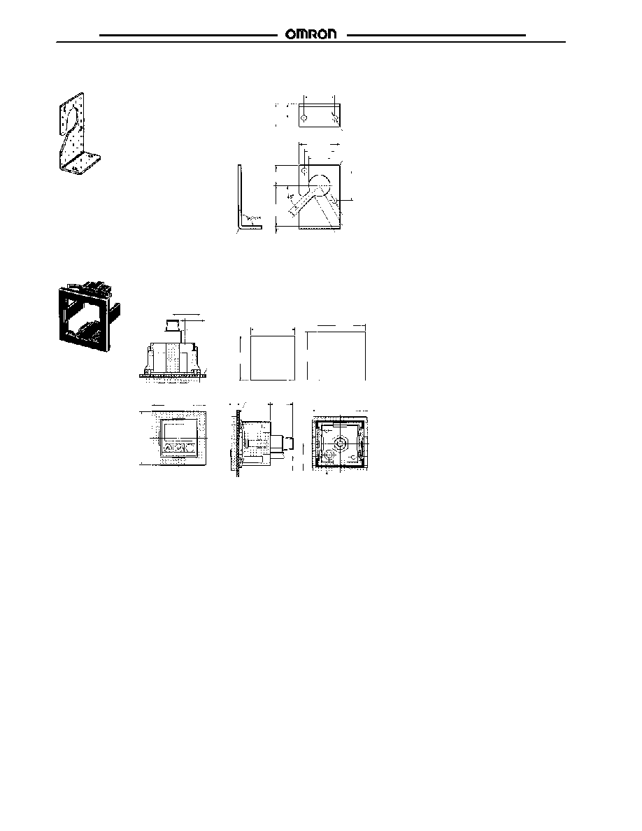
J
ACCESSORIES
E89-F3 Mounting Bracket
Two-3.5 (0.14) dia.
* Provided with E8F2
Four-R1 (R0.04)
13.5
(0.53)
9
(0.35)
20.5
(0.81)
20 (0.79)
20
(0.79)
26.9
(1.06)
1.6
(0.06)
4.5
(0.18)
27 (1.06)
14.5
(0.57)
15
±0.4
(0.59)
Two-3.5 (0.14) dia.
R7.25 (R0.29)
Four-R2.5 (R0.10)
R1.6 (R0.06)
J
E89-F4 PANEL-MOUNTING BRACKET (SOLD SEPARATELY)
0
Panel
Panel Cutout Dimensions
(E89-F4 is available in the following two sizes.)
Spacer not mounted
Spacer mounted
33
+0.5
40
(1.57)
Note: The spacer can be removed from the panel-
mounting bracket. The panel cutout dimen-
sions can be adjusted as shown above by
attaching or detaching the spacer.
(1.30
+0.02
)
36
+0.5
33
+0.5
(1.42
+0.02
)
(1.42
+0.02
)
0
0
0
0
0
0
0
36
+0.5
41.3 (1.63)
20
(0.79)
11.5
(0.45)
25 (0.98)
4
(0.16)
Panel
Spacer
40 (1.57)
20.65 (0.81)
12.15
(0.48)
(1.30
+0.02
)
17
(0.67)
E8F2
E8F2
Precautions
J
ENVIRONMENT
∑
Do not use the Sensor in locations subject to explosive or
flammable gases.
∑
Do not use the Sensor in an environment subject to corrosive
or combustible gases.
∑
Make sure that the Sensor is free of water.
J
AVOID DAMAGE TO THE E8F2
∑
Do not impose any voltage exceeding the rated voltage on
the E8F2.
∑
Do not short-circuit the load connected to the E8F2.
∑
When supplying power to the E8F2, make sure that the po-
larity of the power is correct.
J
WIRING
∑
Do not wire power lines or high-tension lines adjacent to the
lines of the E8F2.
∑
If no linear output is used, cut the gray lead wire short and
apply insulating tape to the lead wire so that it will not come
into contact with any other terminal.
J
MOUNTING
∑
Mount the Sensor so that ultrasonic vibrations will not be
applied directly to the Sensor.
∑
Do not insert any wire into the pressure port. Doing so may
damage the pressure elements and cause a malfunction.
∑
Do not apply a tensile strength in excess of 50 N (11.25 lbs)
to the cords or connectors.
∑
The pressure-introducing section (aluminum die-cast made)
is fixed with tapered 1/8 NPT male screws and M5 female
screws. When using tapered screws, use tapered 1/8 NPT
female screws.
∑
Wrap the tapered 1/8 NPT male screws with sealing tape to
prevent any leakage. Tighten the male screws to a torque of
10 NSm (7.38 ftSlbs) max.
∑
Tighten M5 female screws to a torque of 2 NSm
(1.48 ftSlbs) max.
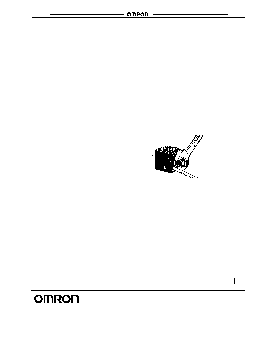
∑
Tightening each male screw by using a 12-mm wrench to
hold its hexagonal head, not the screw itself.
Hexagonal head
E8F2
∑
When attaching the Mounting Bracket to the Sensor, make
sure that each M3 screw is tightened to a torque of
0.5 NSm (0.37 ftSlbs) max.
Cat. No. CEDSAX4 11/01 Specifications subject to change without notice. Printed in U.S.A.
OMRON ELECTRONICS LLC
One East Commerce Drive
Schaumburg, IL 60173
NOTE: DIMENSIONS SHOWN ARE IN MILLIMETERS. To convert millimeters to inches divide by 25.4.
1-800-55-OMRON
OMRON CANADA, INC.
885 Milner Avenue
Scarborough, Ontario M1B 5V8
416-286-6465
R
OMRON ON--LINE
Global -- http://www.omron.com
USA -- http://www.omron.com/oei
Canada -- http://www.omron.com/oci