Document Outline
- First Page
- Ordering Information
- Specifications
- Engineering Data (Typical)
- Nomenclature
- Operation
- Dimensions
- Installation
- Precautions
- Contacting Omron
R
2
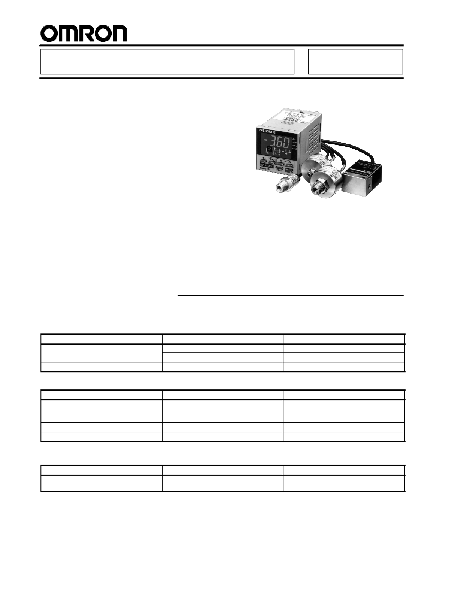
Pressure Sensor
E8M/E8MS
Four-channel Pressure Sensor Offers
Versatile Functions and High Precision
Without Errors
H
The industry's smallest pressure sensor,
compact, lightweight -- ideal for robot arms
or other moving components
H
A highly sensitive minute-pressure sensor
model detects very small differences in air
pressure
H
Requires no wiring conduit -- can be
located for sensing in small places
H
Simple display panel efficiently saves
space, but offers large LEDs
H
Easy sensitivity adjustment using the teach
function and channel-to-channel copy
function
Ordering Information
J
SENSORS
E8MS
Type
Pressure range description
Part number
Positive pressure sensor
0 to 100 kPa (0 to 14.5 psi)
E8MS-01
Positive pressure sensor
0 to 1 MPa (0 to 145 psi)
E8MS-10
Negative pressure sensor
0 to --101 kPa (0 to --14.6 psi)
E8MS-N0
E8M
Type
Pressure range description
Part number
Minute differential pressure sensor
Differential pressure from 0 to 1,000 Pa
(0 to 0.145 psi) between positive and
negative ports
E8M-A1
Positive pressure sensor
0 to 1 MPa (0 to 145 psi)
E8M-10
Negative pressure sensor
0 to --101 kPa (0 to --14.6 psi)
E8M-N0
J
CONTROLLER
Item
Description
Part number
Controller
Optional for pressure sensors:
K3C-MP8-T1Z
Controller
Optional for pressure sensors:
E8M series and E8MS series
K3C MP8 T1Z
E8M/E8MS
E8M/E8MS
3
J
ACCESSORIES (ORDER SEPARATELY)
Item
Description
Part number
Sensor connector cable
4-pin connector with 3-m cable required for E8M-10 and E8M-N0
(Note: E8M-A1 does not require this cable.)
E89-M3
3-pin connector with 3-m cable required for E8MS-01, E8MS-10 and
E8MS-N0
E89-M4
Cable connector
Replacement cable connector for the E89-M3 and E89-M4 Sensor
connector cables.
(Note: This connector is provided with the E89-M3 and E89-M4
cables. As a replacement connector, it can be purchased separately.)
XS8A-0442
Connector cable for K3C
controller
7-pin connector with 2-m cable required for K3C controller
K32-MP2W
Soft cover
Clear rubber cover for K3C controller
Y92A-48F1
Hard cover
Clear plastic cover for K3C controller
Y92A-48
Specifications
J
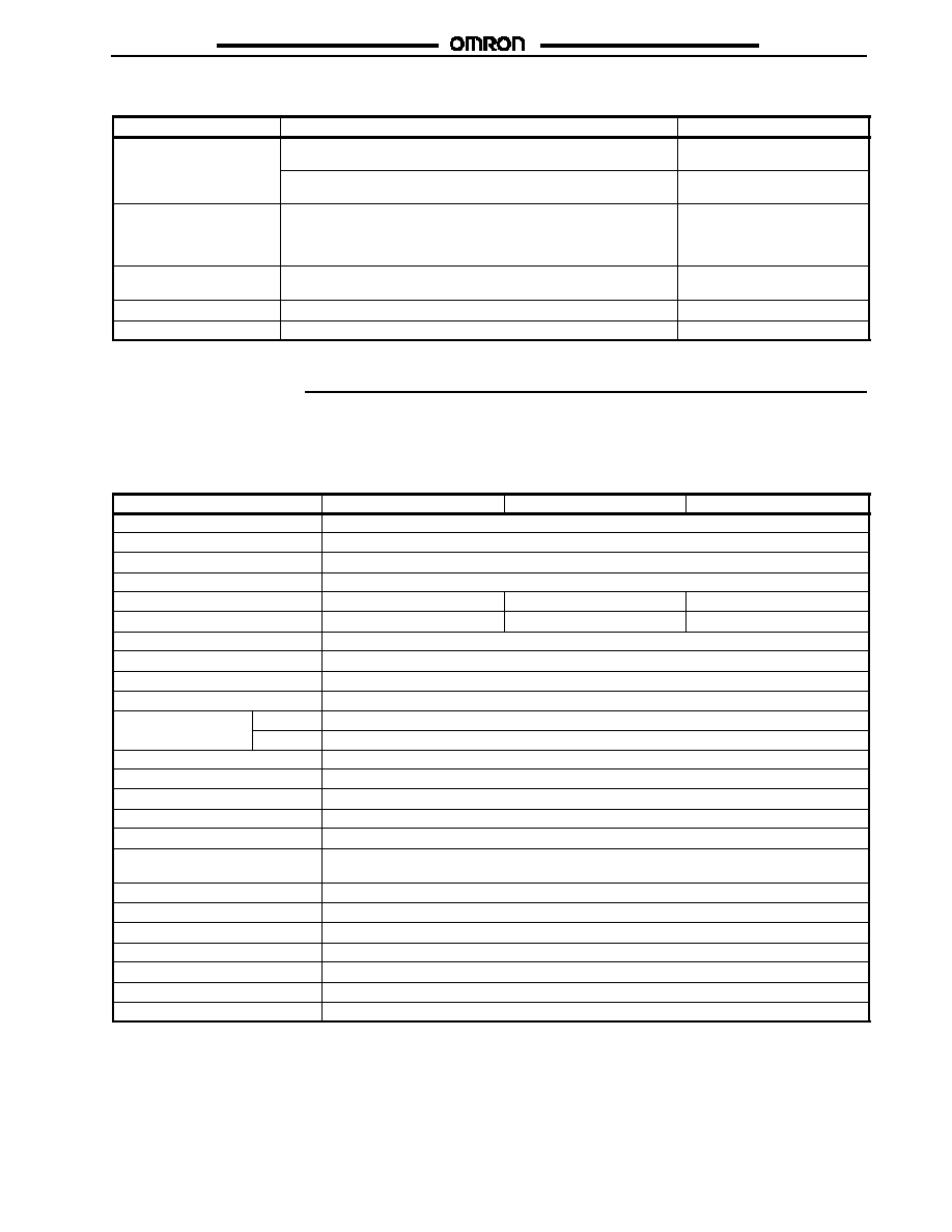
RATINGS/CHARACTERISTICS
Sensors
E8MS
Item
E8MS-01
E8MS-10
E8MS-N0
Power supply voltage
12 VDC�10%, ripple (p-p) of 5% max.
Current consumption
25 mA max.
Pressure type
Gauge pressure
Applicable fluid
Non-corrosive gas and non-flammable gas
Rated pressure range
0 to 100 kPa (0 to 14.5 psi)
0 to 1 MPa (0 to 145 psi)
0 to --101 kPa (0 to --14.6 psi)
Withstand pressure
400 kPa (58 psi)
1.5 MPa (217.5 psi)
400 kPa (58 psi)
Linearity
�1% FS max.
Hysteresis
�1% FS max.
Output (linear output)
Voltage output: 1 to 5 V with an output impedance of 1 k
Protection circuit
Reverse polarity connection, load short-circuiting
Ambient temperature
Operating
0�C to 50�C (32�F to 122�F)
Ambient temperature
Storage
--15� to 60�C with no icing (5�F to 140�F)
Ambient humidity
35 to 85% with no condensation
Temperature influence
�0.12% FS/�C max.
Voltage influence
�1% FS max.
Insulation resistance
100 M min. (500 VDC) between current-carry parts and case
Dielectric strength
1,000 VAC 1 min
Vibration resistance
10 to 150 Hz, 0.35-mm single amplitude or 50 m/s
2
(approx. 5G) for 8 min for 10 times each in X,
Y, and Z directions
Shock resistance
500 m/s
2
(approx. 50G) for 3 times each in X, Y, and Z directions.
Enclosure rating
IEC60529 IP50
Pressure joint
1/8 NPT and M5 female screw
Connection method
Connector (use the E89-M4, sold separately)
Weight (packaged weight)
Approx. 6 g (0.21 oz.)
Material
Pressure joint: Aluminum
Accessories
Instruction manual
E8M/E8MS
E8M/E8MS
4
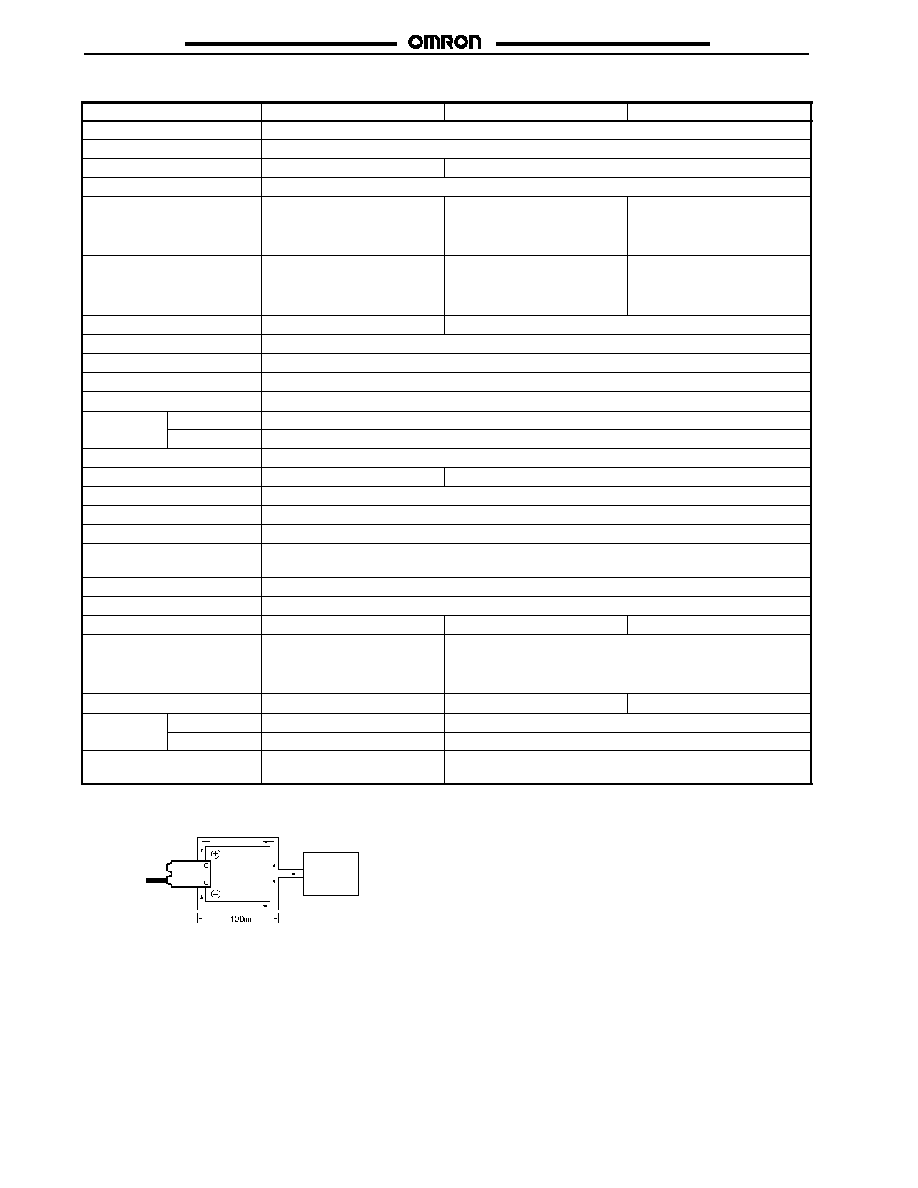
E8M
Item
E8M-A1
E8M-10
E8M-N0
Power Supply voltage
12 VDC�10%, ripple (p-p) of 5% max.
Current consumption
30 mA max.
Pressure type
Differential pressure
Gauge pressure
Applicable fluid
Non-corrosive gas and non-flammable gas
Rated pressure range
Differential pressure from 0 to
1,000 Pa ( 0 to 0.145 psi)
between positive and negative
ports
0 to 1 MPa (0 to 145 psi)
0 to --101 kPa (0 to --14.6 psi)
Withstand pressure
Differential pressure from 0 to
2,500 Pa (0 to 0.36 psi) between
positive and negative ports
(see note)
1.5 MPa ( 217.5 psi)
400 kPa (58 psi)
Accuracy
�3% FS max.
�5% FS max.
Linearity
�1% FS max.
Hysteresis
�1% FS max.
Output (linear output)
Voltage output: 1 to 5 V with an output impedance of 1 k
Protection circuit
Reverse polarity connection, load short-circuiting
Ambient
Operating
0�C to 40�C (32�F to 104�F)
Ambient
temperature
Storage
--15� to 50�C with no icing (5�F to 122�F)
Ambient humidity
35 to 85% with no condensation
Temperature influence
�0.25% FS/�C max.
�0.12% FS/�C max.
Voltage influence
�3% FS max.
Insulation resistance
100 M min. at 500 VDC between current-carry parts and case
Dielectric strength
1,000 VAC 1 min
Vibration resistance
10 to 150 Hz, 0.75-mm single amplitude or 100 m/s
2
(approx.10G) for 8 min for 4 times each in X, Y,
and Z directions
Shock resistance
300 m/s
2
(approx. 30G) for 3 times each in X, Y, and Z directions.
Enclosure rating
IEC60529 IP50
Pressure joint
M5 female screw
1/8 NPT and M5 female screw
M5 male screw
Connection method
4 mm (0.16 in.) dia.
4 conductor, vinyl-insulated
cord; standard length:
3m (9.84 ft.)
Connector (use the E89-M3, sold separately)
Weight (packaged weight)
Approx. 130 g (4.59 oz.)
Approx. 30 g (1.06 oz.)
Approx. 20 g (0.71 oz.)
Material
Pressure joint
SUS303
SUS304
Material
Case
ABS
Aluminum, polyether sulfonic resin
Accessories
Pin Controller Connector,
instruction manual
Instruction manual
Note: The absolute pressure value of each port is 100 kPa. (14.5 psi)
E8M-A1
Pressure
generator
Measurement method
E8M/E8MS
E8M/E8MS
5
Controllers
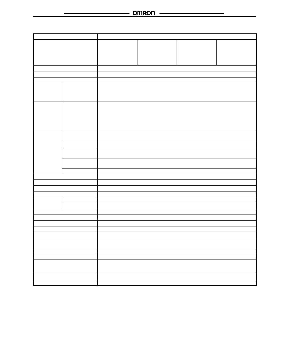
Item
K3C-MP8-T1Z
Connectable Pressure Sensor
E8M-A1
Differential pressure
from 0 to 1,000 Pa
(0 to 0.145 psi)
between positive and
negative ports
E8MS-01
0 to 100 kPa
(0 to 14.5 psi)
E8MS-10 E8M-10
0 to 1 MPa
(0 to 145 psi)
E8MS-N0, E8M-N0
0 to --101 kPa
(0 to --14.6 psi)
Power Supply voltage
24 VDC �10%, ripple (p-p) 10% max.
Current consumption
200 mA max.
Sensor power supply
Supplied from the Controller, 12 VDC�10% (120 mA max. for the total channels used)
Input
Sensor input
(through 4-pin
one-touch
connector)
Input voltage range: 1 to 5 VDC with an impedance of 1 M per channel
Output
Comparative
output
NPN open collector
Flow current:
30 mA max.
Applied voltage:
30 VDC max.
Residual voltage:
0.8 V max. with a flow current of 30 mA
0.4 V max. with a flow current of 16 mA
NO or NC (selectable) independent output in hysteresis or wind comparator mode (selectable)
on each channel
Indicators
Measurement
value
LED indicator (red) with a character height of 10.8 mm for 3
1
/
2
digits for a single channel
selected.
Message
LED indicator (red) with a character height of 10.8 mm for 3
1
/
2
digits.
Measurement and
setting channel
LED indicator (green) with a character height of 7.2 mm for 1 digit.
Comparative
output
LED indicator (orange) that is lit when the output transistor is turned ON
Others
LED indicator (green) for connecting channel and unit display (green)
Response speed
5 ms max.
Set resolution
�0.1% FS max.
Display precision
�1% FS max.
Protection circuit
Reverse polarity connection, load short-circuiting
Ambient
Operating
0� to 50�C (32�F to 122�F)
Ambient
temperature
Storage
--10� to 60�C with no icing (14�F to 140�F)
Ambient humidity
35 to 85% RH with no icing
Supply voltage influence
�1% FS max.
Temperature influence
�1% FS max.
Insulation resistance
100 M min. (500 VDC) between current-carry parts and case
Dielectric strength
1,000 VAC 1 min
Vibration resistance
10 to 150 Hz, 0.75-mm single amplitude or 100 m/s
2
(approx. 10G) for 8 min for 4 times each in
X, Y, and Z directions
Shock resistance
300 m/s
2
(approx. 30G) for 3 times each in X, Y, and Z directions.
Enclosure rating
IEC60529 IP40
Connecting method
Panel mounting
Power supply and output: 7-pin terminal
Sensor I/O: 4-pin connector
Weight (packaged weight)
Approx. 90 g (3.17 oz.)
Accessories
Instruction manual, Adapter
E8M/E8MS
E8M/E8MS
6
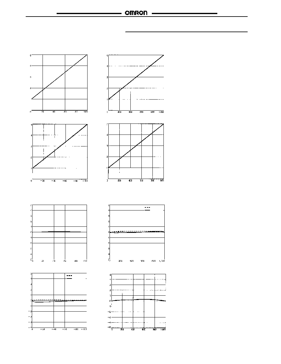
Engineering Data (Typical)
J
LINEAR OUTPUT VOLTAGE VS. PRESSURE
E8MS-01
E8MS-10/E8M-10
E8MS-N0/E8M-N0
Linear
out
put
v
o
lt
age
(
V
)
Linear
out
put
v
o
lt
age
(
V
)
Linear
out
put
v
o
lt
age
(
V
)
Pressure (kPa)
Pressure (kPa)
E8M-A1
Linear
out
put
v
o
lt
age
(
V
)
Differential pressure (Pa) between positive and negative ports
Pressure (kPa)
J
OUTPUT LINEARITY
E8MS-01
E8MS-10/E8M-10
E8MS-N0/E8M-N0
Linear
it
y
dev
iat
i
on
(
%
F
S
)
Linear
it
y
dev
iat
i
on
(
%
F
S
)
Linear
it
y
dev
iat
i
on
(
%
F
S
)
Pressure (kPa)
Pressure (kPa)
E8M-A1
Linear
it
y
dev
iat
i
on
(
%
F
S
)
Differential pressure (Pa) between positive and negative ports
Pressure (kPa)
E8MS-10
E8M-10
E8MS-N0
E8M-N0
E8M/E8MS
E8M/E8MS
7
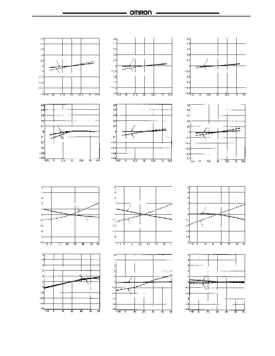
J
LINEAR OUTPUT FLUCTUATION VS. POWER
E8MS-01
E8MS-10
E8MS-N0
Linear
out
put
f
l
uc
t
uat
ion
(
%
F
S
)
Voltage (V)
Voltage (V)
Voltage (V)
Linear
out
put
f
l
uc
t
uat
ion
(
%
F
S
)
Linear
out
put
f
l
uc
t
uat
ion
(
%
F
S
)
Pressure 0
Rated pressure
Pressure 0
Rated pressure
Pressure 0
Rated pressure
E8M-A1
E8M-10
E8M-N0
Linear
out
put
f
l
uc
t
uat
ion
(
%
F
S
)
Voltage (V)
Voltage (V)
Voltage (V)
Linear
out
put
f
l
uc
t
uat
ion
(
%
F
S
)
Linear
out
put
f
l
uc
t
uat
ion
(
%
F
S
)
Pressure 0
Rated pressure
Pressure 0
Rated pressure
Pressure 0
Rated pressure
J
LINEAR OUTPUT FLUCTUATION VS. TEMPERATURE
E8MS-01
E8MS-10
E8MS-N0
Linear
out
put
f
l
uc
t
uat
ion
(
%
F
S
)
Temperature(�C)
Temperature(�C)
Temperature (�C)
Linear
out
put
f
l
uc
t
uat
ion
(
%
F
S
)
Linear
out
put
f
l
uc
t
uat
ion
(
%
F
S
)
Pressure 0
Rated pressure
Pressure 0
Rated pressure
Pressure 0
Rated pressure
E8M-A1
E8M-10
E8M-N0
Linear
out
put
f
l
uc
t
uat
ion
(
%
F
S
)
Temperature(�C)
Temperature(�C)
Temperature (�C)
Linear
out
put
f
l
uc
t
uat
ion
(
%
F
S
)
Linear
out
put
f
l
uc
t
uat
ion
(
%
F
S
)
Pressure 0
Rated pressure
Pressure 0
Rated pressure
Pressure 0
Rated pressure
E8M/E8MS
E8M/E8MS
8
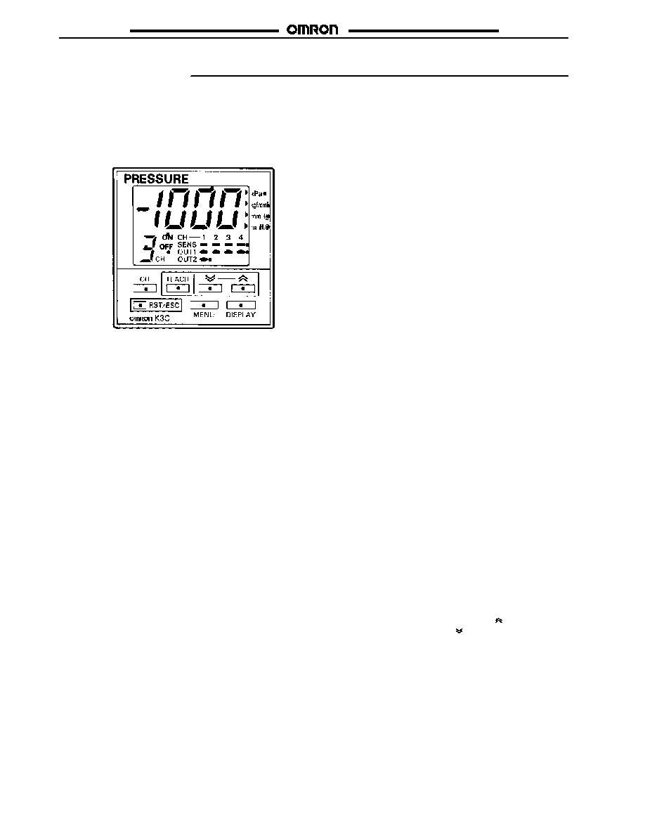
Nomenclature
J
PRESSURE SENSOR CONTROLLER
K3C Controller
1
2
3
4
5
14
13
12
11
10
6
7
8
9
Display Panel
1. Numeric and Menu Display (Main Display)
Indicates measurement values and setting menu items.
(Red)
2. Unit Indicator
Indicates the unit used for sensing. The unit indicated on the
indicator is the one currently set. (Green)
3. Sensor Indicator
Indicates the operating conditions of Sensors connected to
the K3C. When the Sensors are in operation, corresponding
indicators are lit. (Green)
Sensors can be connected to channels 1 to 4. Channel 1 has
two outputs.
4. OUT1 Indicator
Lit when OUT1 is turned ON. (Orange)
5. OUT2 Indicator
Lit when OUT2 is turned ON. (Orange)
6. ON-point Indicator (See Output Control in the Operation
Section.)
The ON-point value presently set is displayed in the main
display when the ON-point indicator is lit.
7. Channel Display
Displays the channel of a Sensor to be in operation or where
data is being set. Channels 1 through 4 are available.
(Green)
8. OFF-point Indicator
The OFF-point value presently set is displayed in the main
display when the OFF-point indicator is lit. (Orange)
Operation Keys
9. CH
Used to select the channel of a Sensor to be in operation or
where menu items are set. A channel is selected in sequence
1 to 4 by repeatedly pressing the CH Key.
10. RST/ESC
Used to return to the previous menu. If the RST/ESC Key is
pressed right after a set value change, the new set value will
be canceled and the display will return to the previous menu.
The Controller will be zero-reset if the RST/ESC Key is
pressed for 1 s minimum.
11. TEACH
Used for teaching settings.
12. MENU
Used to select the measurement mode or set mode, to
change menu items in set mode, and to enter set values.
13. DISPLAY
Used to select the measurement value, ON-point, or OFF-
point display in measurement mode.
Set menu or set value display is selected in set mode.
14. UP/Down
Used to change the set values in set mode.
The values increase by pressing the Up ( ) Key and de-
crease by pressing the Down ( ) Key.
E8M/E8MS
E8M/E8MS
9
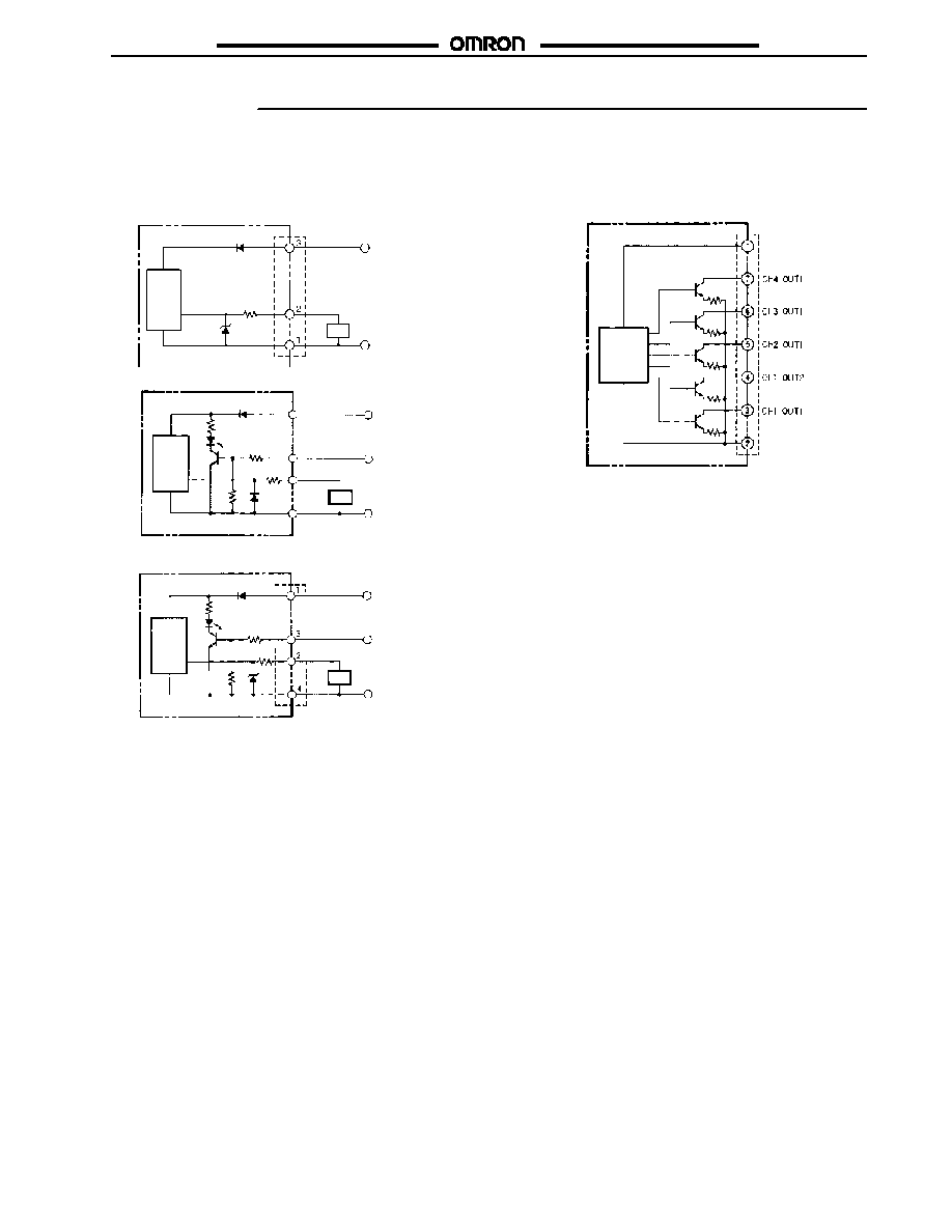
Operation
J
OUTPUT CIRCUITS
Sensor
Output Configuration: 1 to 5 V Linear Output
E8M-A1
E8M-10, E8M-N0
Pressure
Sensor
main
circuit
Power
indicator
(green)
Brown
Pink
Black (linear output)
Load
Blue
Pressure
Sensor
main
circuit
Power
indicator
(green)
Brown
Pink
Black (linear output)
Load
Blue
Connector
+ V
0/5 V
0 V
Input
+ V
0/5 V
0 V
Input
E8MS-01, E8MS-10, E8MS-N0
Brown
Black (linear output)
Load
Blue
Connector
0 V
+ V
Pressure
Sensor
main
circuit
Controller
Output Configuration: NPN Output
Note: The above colors indicate the conductor colors of the
K32-MP2W (Power and output connector for K3C
Controller).
Pressure
Controller
main
circuit
Connector
+ V
0 V
(brown)
(pink)
(orange)
(gray)
(white)
(black)
(blue)
K3C-MP8-T1Z
E8M/E8MS
E8M/E8MS
10
J
DISPLAYS OF SETTINGS AND MEASUREMENTS
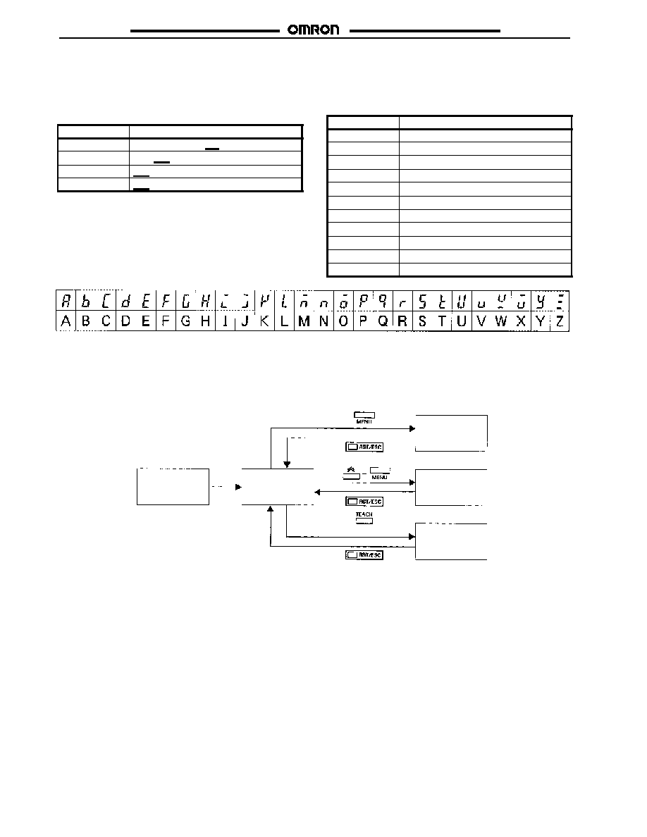
Digital Display
The E8M displays alphanumeric characters,such as measurement
values and menu items, with 7-segment LEDs as shown below for
example.
Display
Meaning
set
ON and OFF-point Settings
kpa
Unit (kPa)
wid
Width
aUe
Average
The following abbreviations are used for the digital display of the
Controller.
Abbreviation
Meaning
SET
Setting
UNT
Unit
OPE
Operation
SEN
Sensor
PRT
Protect
COP
Copy
HYS
Hysteresis
WID
Width
AUT
Auto
DSP
Display
AVE
Average
J
MODES
In addition to a measurement value display function, the K3C has a variety of functions including an external device control function.
These functions are available in four main modes as described below, where characters in parentheses indicate the digital display condi-
tions. For the relationship among each mode and for switching methods, refer to the following figure.
Power ON
Measurement
mode
Basic setting
mode
Special
setting mode
Teaching
mode
1 s min.
E8M/E8MS
E8M/E8MS
11
Measurement Mode
The K3C is in this mode when power is turned ON. Normally use the Controller in this mode.
Basic Setting Mode
ON- or OFF-point value
settings and change
Measurement unit selection
Output type selection:
Normally open or normally
closed
Sensor type selection
Teaching Mode
Values can be set automatically using measurement values instead of key input.
Special Setting Mode
Key-protect function for
set value protection
Data copy function to copy
the data of channels
Original pressure
fluctuation compensation
setting
Hysteresis width
Window width setting
Measurement value
display refresh interval
setting
Number of measurement
times setting for
measurement value
averaging
E8M/E8MS
E8M/E8MS
12
J
SETTINGS
The Controller in pressure sensing operation requires basic
settings, such as Pressure Sensor type and measurement
unit settings as described in the procedure below.
1. Turning ON the Power
Turn ON the K3C after making sure that the Sensors and
power supply to be used are properly connected to the
Controller.
Four Pressure Sensors can be connected to the K3C, one of
which can be selected with the K3C for measurement value
display.
CH1 to CH4 correspond to the four Pressure Sensors
respectively.
The K3C displays the measurement value of channel 1 right
after the K3C is turned ON.
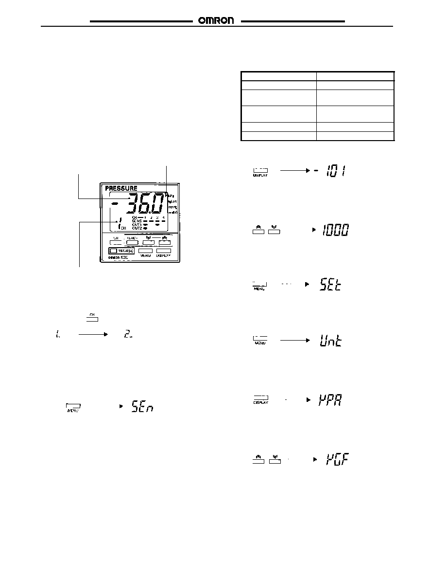
The measurement value
appears right after the
K3C is turned ON.
The default unit is kPa.
The Sensor on channel 1 is in operation.
2. Channel Selection
Press the CH Key to select the channel to be used. A
channel is selected in the sequence 1 2 3 4 by
repeatedly pressing the CH Key.
Press the CH Key.
The next channel is selected.
Channel 1 is selected right after the K3C is turned ON. Select
the channel where the Sensor to be used is connected. After
the channel is selected, set the Sensor type and
measurement unit.
3. Sensor Type Selection
Press the MENU Key four times so that "SEN" will appear.
Press the MENU
Key four times.
The display changes.
If the display does not change when the MENU Key is
pressed, the key-protect function may be enabled. Refer to
Key-protect Settings (found in the Advanced Operations
Sub-Section) and disable the key-protect function.
Select the Sensor type according to the target object.
The following Sensor types are available.
Model
Display
E8M-A1
--1
E8MS-N0
E8M-N0
--101
E8MS-10
E8M-10
1000
Not connected
---
E8MS-01
100
Press the DISPLAY Key once.
A Sensor type appears in the main display.
Press the DISPLAY
Key once.
A preset Sensor type appears.
The sensor indicator for the selected Sensor type flashes.
Press the Up or Down Key to select the Sensor type
according to the Sensor to be used.
Press the Up or Down Key.
The Sensor type changes.
After selecting the Sensor type, press the MENU Key once to
enter the Sensor type.
The main display will change to "SET."
Press the MENU
Key once.
The display changes to "SET."
4. Measurement Unit Selection
Press the MENU Key once. The main display will change to
"UNT" from "SET."
Press the MENU
Key once.
The display changes to "UNT."
Press the DISPLAY Key once.
A measurement unit will appear in the main display.
The LED display of the selected unit is lit.
Press the DISPLAY
Key once.
Measurement unit appears.
Press the Up or Down Key to select the measurement unit to
be used.
The LED display of the selected unit is lit.
Press the Up or Down Key.
Note: Selectable measurement units vary with the Sensor type.
Any measurement unit that cannot be selected will be
skipped.
E8M/E8MS
E8M/E8MS
13
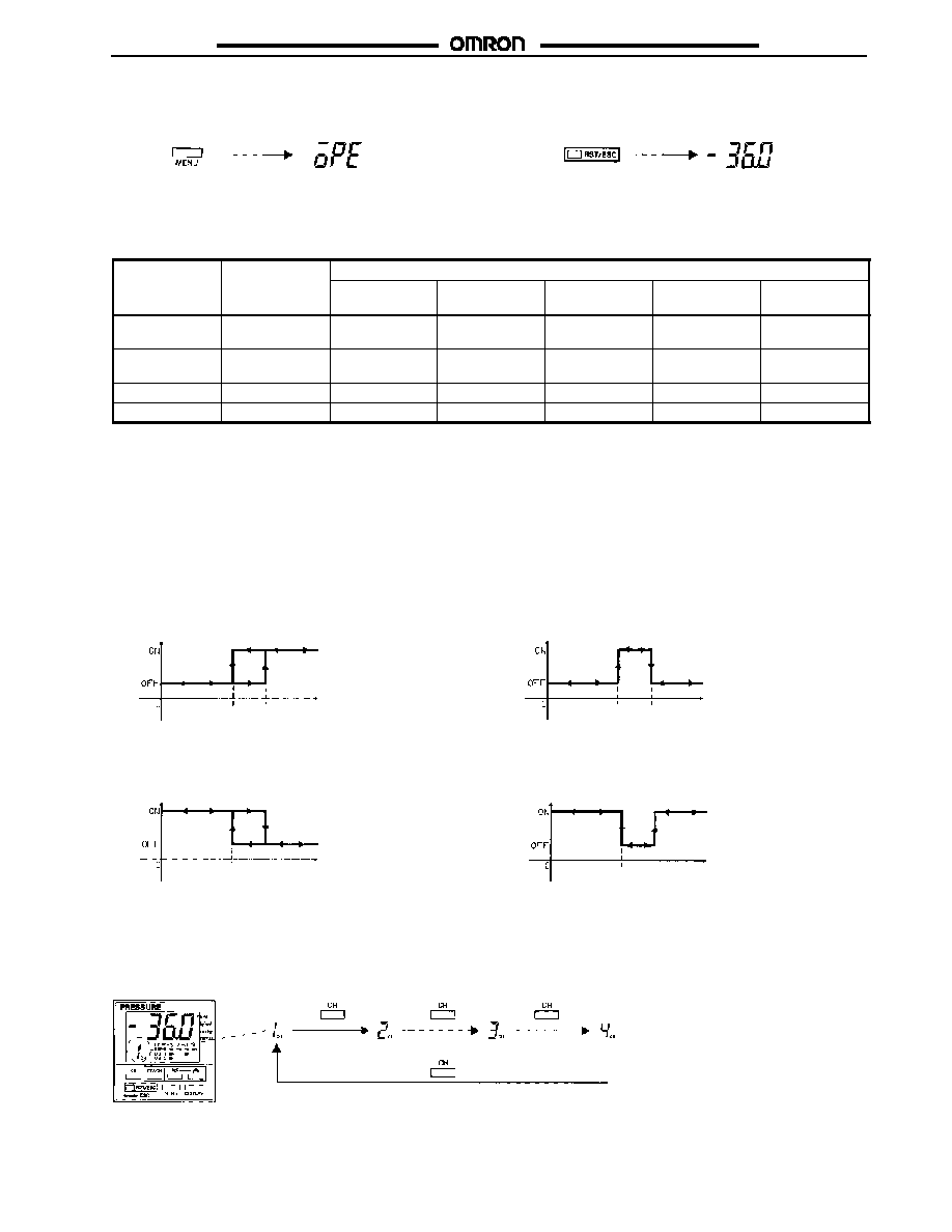
After the measurement unit is selected, press the MENU Key
to enter the measurement unit.
The display will change to "OPE."
Press the MENU
Key once.
The display changes to
"OPE."
Press the RST/ESC Key.
The measurement value will appear in a present setting. This
state is called the "measurement mode."
Press the RST/ESC
Key once.
The present measurement
value appears.
The basic settings are complete.
Refernce Table for Sensor Types and Availability of Measurement Units
Sensor type
Pressure range
Display unit
Sensor type
Pressure range
kpa
(kPa)
kgf
(kgf/cm
2
)
hg
(mmHg)
h2o
(mmH
2
O)
Uol
(vol)
(see note)
E8MS-N0
E8M-N0
0 to --101 kPa
Yes
Yes
Yes
No
Yes
E8MS-10
E8M-10
0 to 1 MPa
Yes
Yes
No
No
Yes
E8M-A1
0 to --1,000 Pa
Yes
No
No
Yes
Yes
E8MS-01
0 to 100 kPa
Yes
Yes
No
No
Yes
Note: Select Uol for voltage display.
J
OUTPUT CONTROL
The K3C has output according to the measurement value. The output can be used to control external devices, such as valves and absorption
systems.
To control an external device, a reference value must be set so that the output can be turned ON if the measurement value is above the refer-
ence value and turned OFF if the measurement value is below the reference value. (The ON/OFF setting can be reversed.)
The value turning the outputON is called the ON pointand the value turning the outputOFF is called the OFF point.The following is an example
of ON- and OFF-point settings on condition that the Controller has normally open output.
Normally Open Output
Hysteresis Mode
Window Mode
Ou
tp
u
t
OFF set
value
ON set
value
Pressure
Ou
tp
u
t
ON set
value
OFF set
value
Pressure
Normally Closed Output
Hysteresis Mode
Window Mode
Ou
tp
u
t
OFF set
value
ON set
value
Pressure
Ou
tp
u
t
ON set
value
OFF set
value
Pressure
Select the channel where the data is to be set.
�
A channel is selected in sequence by repeatedly pressing the CH Key.
�
Data can be set on each channel independently.
�
Be sure that the channel to be set is correct.
E8M/E8MS
E8M/E8MS
14
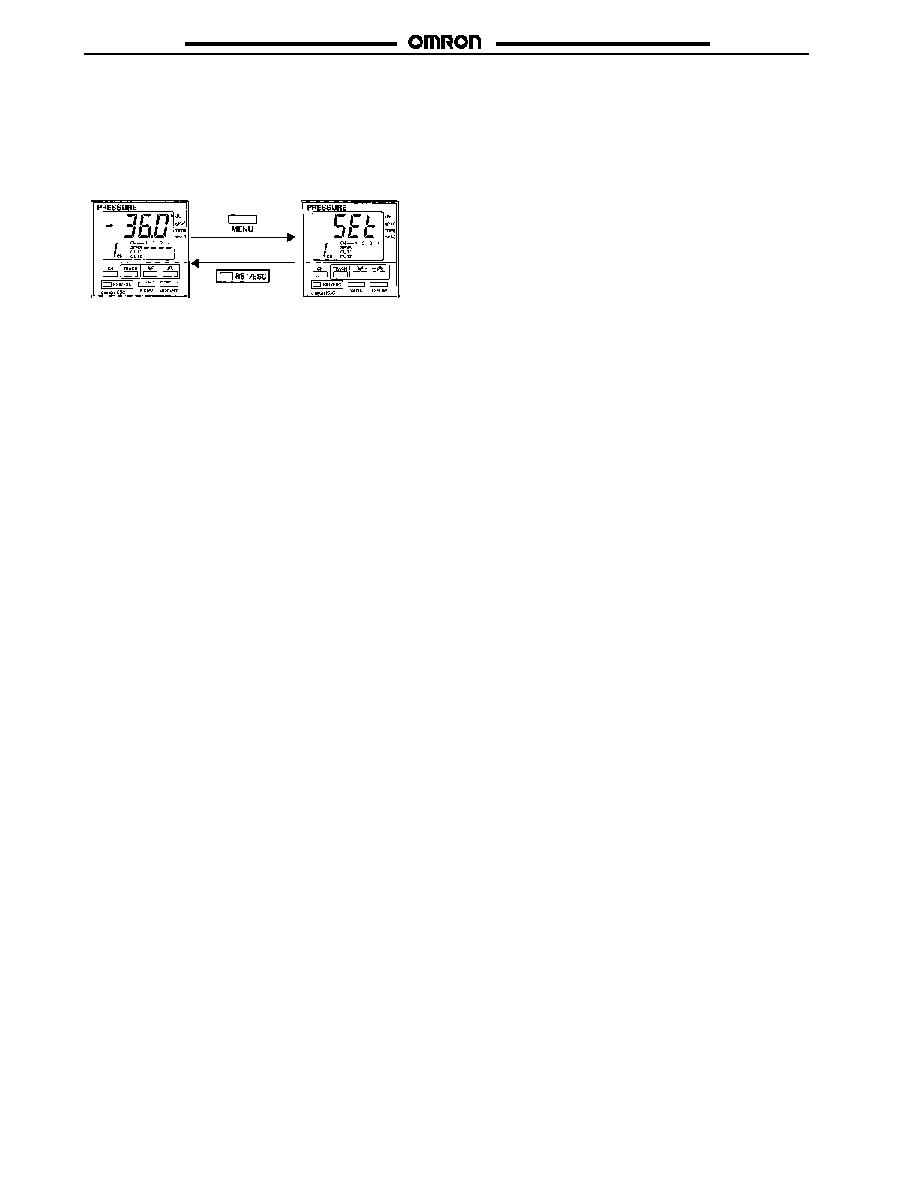
Basic Set Mode
The K3C is in measurement mode right after it is turned ON.
Press the MENU Key once to change the mode to the basic setting mode. "SET" will appear in the main display. If the mode does not
change, the key-protect function may be enabled.
Measurement Mode
Basic Set Mode
ON- and OFF-point Settings
Set ON- and OFF-points for each channel.
Note: 1. The output method varies with the ON and OFF-point settings.
2. When using the E8M-A1 Minute Differential Pressure Sensor, both the ON point and OFF point must be set to the negative
setting. (They cannot be set to the positive setting.)
�
The Controller will be in hysteresis mode if the ON-point set
value is larger than the OFF-point set value.
�
The Controller will be in window mode if the OFF-point set
value is larger than the ON-point set value.
�
The Controller will not be in ON/OFF operation if the ON-
point value is the same as the OFF-point set value.
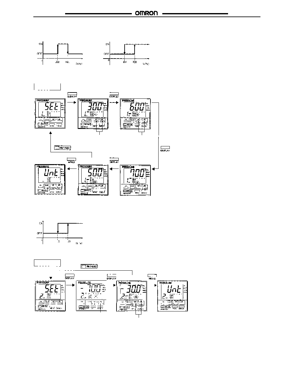
1. Press the DISPLAY Key in basic setting mode with "SET" displayed so that the OUT1 indicator will flash and the ON-point indicator
will be lit.
Press the Up or Down Key to change the ON-point set value of OUT1.
2. Press the DISPLAY Key so that the OUT1 indicator will flash and the OFF-point indicator will be lit.
Press the Up or Down Key to change the OFF-point set value of OUT1.
3. Press the DISPLAY Key so that the OUT2 indicator will flash and the ON-point indicator will be lit.
Press the UP or Down Key to change the ON-point set value of OUT2.
4. Press the DISPLAY Key so that the OUT2 indicator will flash and the OFF-point indicator will be lit.
Press the UP or Down Key to change the OFF-point set value of OUT2.
5. The set values will be entered when the MENU Key is pressed and "UNT" will appear.
Note: If the RST/ESC Key is pressed instead, the set values will not be entered, and "SET" will appear.
When the OUT1 settings are finished and the DISPLAY Key is pressed, OUT2 will be ready for setting only with the channel that has
OUT2 output.
E8M/E8MS
E8M/E8MS
15
Example 1: Channel 1
Ou
tp
u
t
Pressure
Ou
tp
u
t
Pressure
OUT 1
OUT 2
Take the following steps for the above settings with a Sensor with a pressure range of up to 1 MPa.
Channel 1
ON point of OUT1
Press the Up or Down Key
to change the set value.
Cancel
Enter
OFF point of OUT2
Press the Up or Down Key
to change the set value.
OFF point of OUT1
Press the Up or Down Key
to change the set value.
ON point of OUT2
Press the Up or Down Key
to change the set value.
Example 2: Channel 2
Ou
tp
u
t
Pressure
Take the following steps for the above settings with a Sensor with a pressure range of up to --101 kPa.
Channels 2 to 4
Cancel
Enter
ON point of OUT1
Press the Up or Down Key
to change the set value.
OFF point of OUT1
Press the Up or Down Key
to change the set value.
E8M/E8MS
E8M/E8MS
16
J
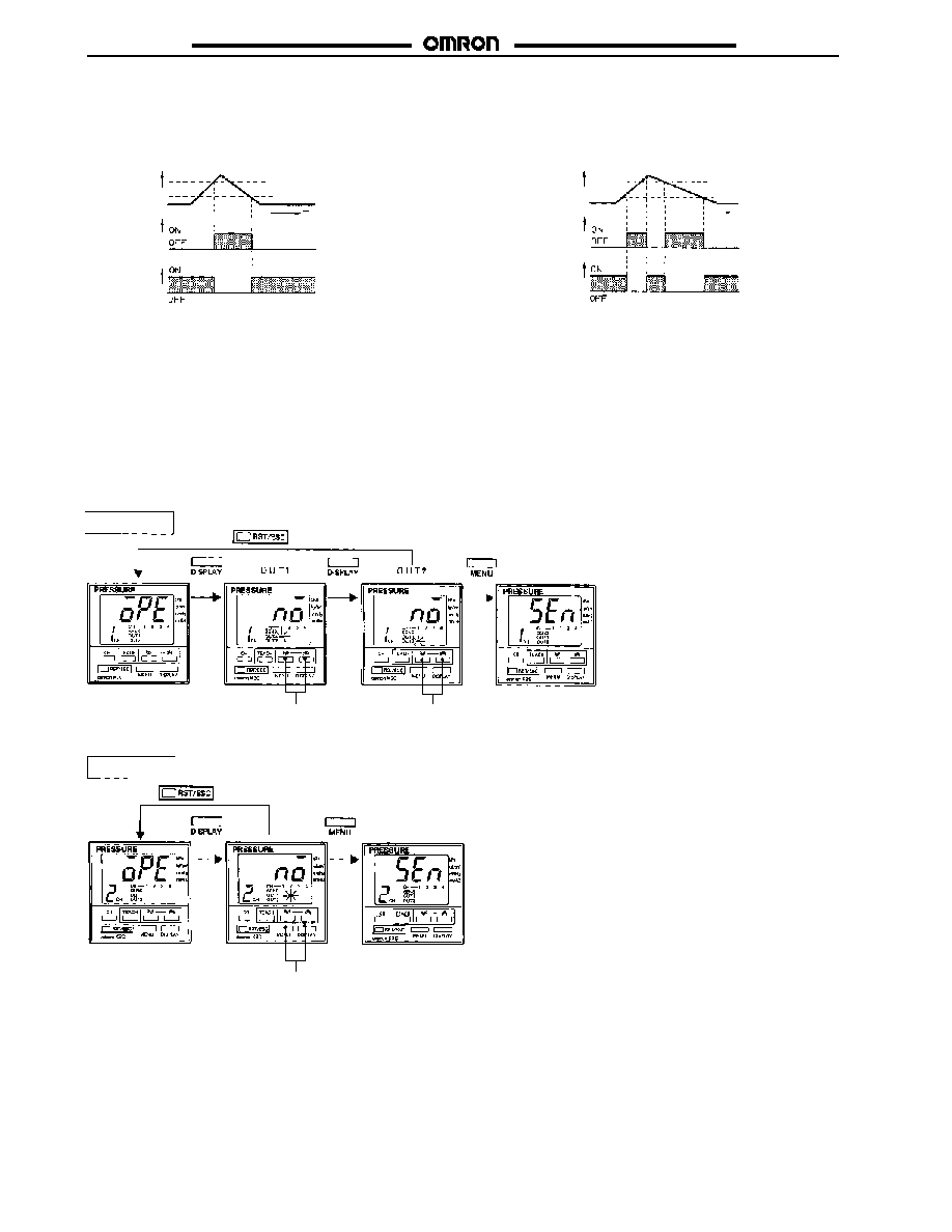
OUTPUT TYPE SELECTION (NORMALLY OPEN OR NORMALLY CLOSED)
Take the following steps to select the output type (normally open or normally closed output) of the K3C.
Hysteresis Mode
Window Mode
Pre
ssu
re
ON point
OFF point
NO output
NC output
Ou
tp
u
t
tr
a
n
s
i
s
to
r
Pre
ssu
re
OFF point
ON point
NO output
NC output
Ou
tp
u
t
tr
a
n
s
i
s
to
r
OFF point --- Hysteresis
ON point --- Hysteresis
Press the MENU Key three times in measurement mode.
"OPE" will appear for output type selection.
The output type presently set will appear by pressing the DISPLAY Key.
NO (normally open) or NC (normally closed) is selected by pressing the Up or Down Key.
By pressing the MENU Key, "SEN" will appear for Sensor type selection after the output type is entered.
If the RST/ESC Key is pressed instead, the set values will not be entered and "OPE" will appear again for output type selection.
When the OUT1 settings are finished and the DISPLAY Key is pressed, OUT2 will be ready for setting only with the channel that has
OUT2 output.
Cancel
Channel 1
Enter
Select NO or NC with
the Up or Down Key.
Select NO or NC with
the Up or Down Key.
Channels 2 to 4
Cancel
Enter
Select NO or NC with
the Up or Down Key.
E8M/E8MS
E8M/E8MS
17
J
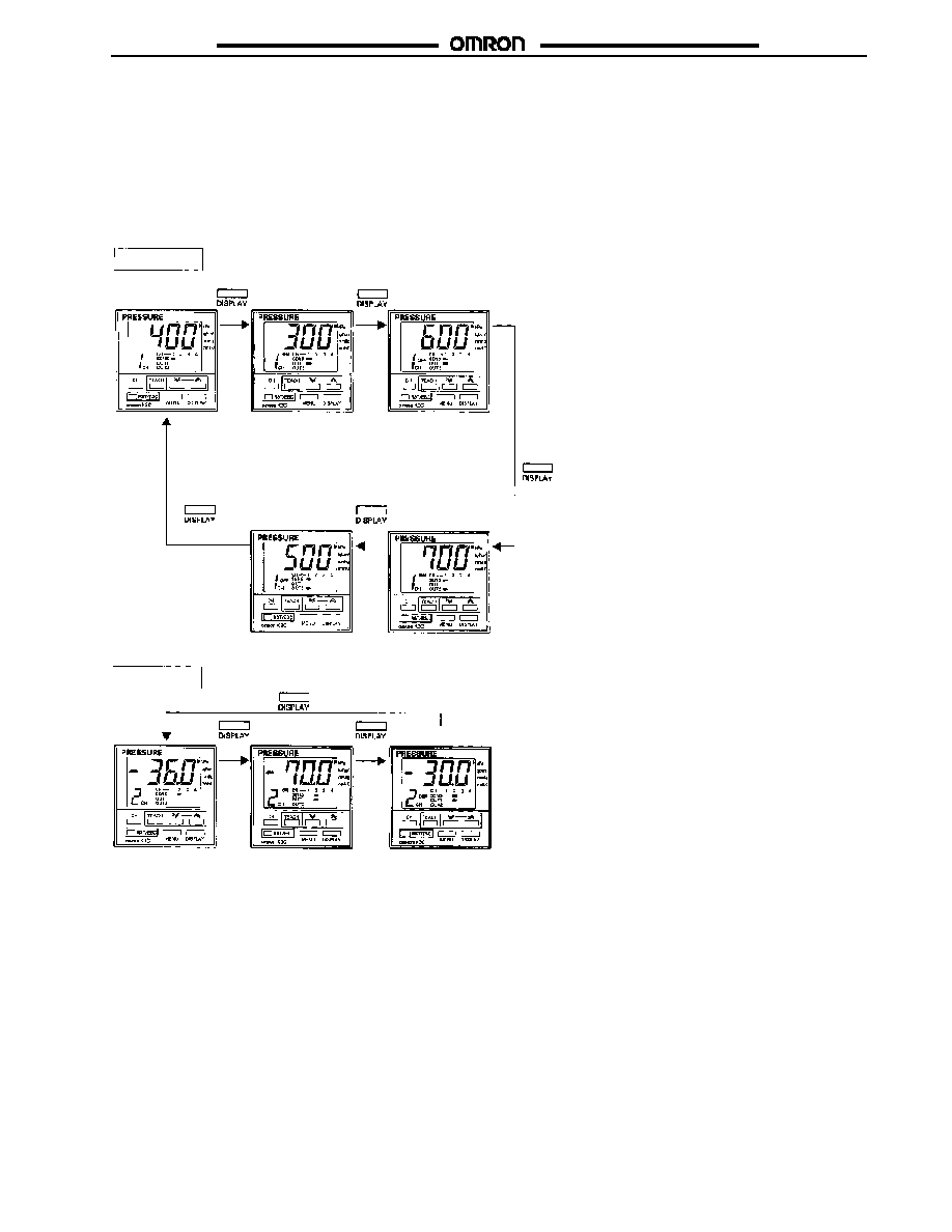
SET VALUE CHECK
The ON point and OFF point presently set can be checked with the following steps.
The ON point presently set will appear by pressing the DISPLAY Key. The OFF point presently set will appear by pressing the DISPLAY
Key again.
By pressing the DISPLAY Key after OUT1 is displayed, the display will change to OUT2 only with the channel that has OUT2 output.
If there is no key input for 2 s during set value display, the display panel will automatically return to the measurement value display.
Channel 1
ON point of OUT1
OFF point of OUT1
OFF point of OUT2
ON point of OUT2
(In the Case of Example 1 on Page 15)
Channels 2 to 4
ON point of OUT1
OFF point of OUT1
(In the Case of Example 2 on page 15)
E8M/E8MS
E8M/E8MS
18
J
ON- AND OFF-POINT SIMPLE SETTING (BY TEACHING)
ON- and OFF-point values can be set by using measurement values instead of key input in the teaching mode.
One-point teaching, which has only one setting point, and two-point teaching, which has two setting points, are both available in the
teaching mode.
One-point Teaching
Two-point Teaching
Ou
tp
u
t
Pressure
Ou
tp
u
t
Pressure
Changing to Teaching Mode
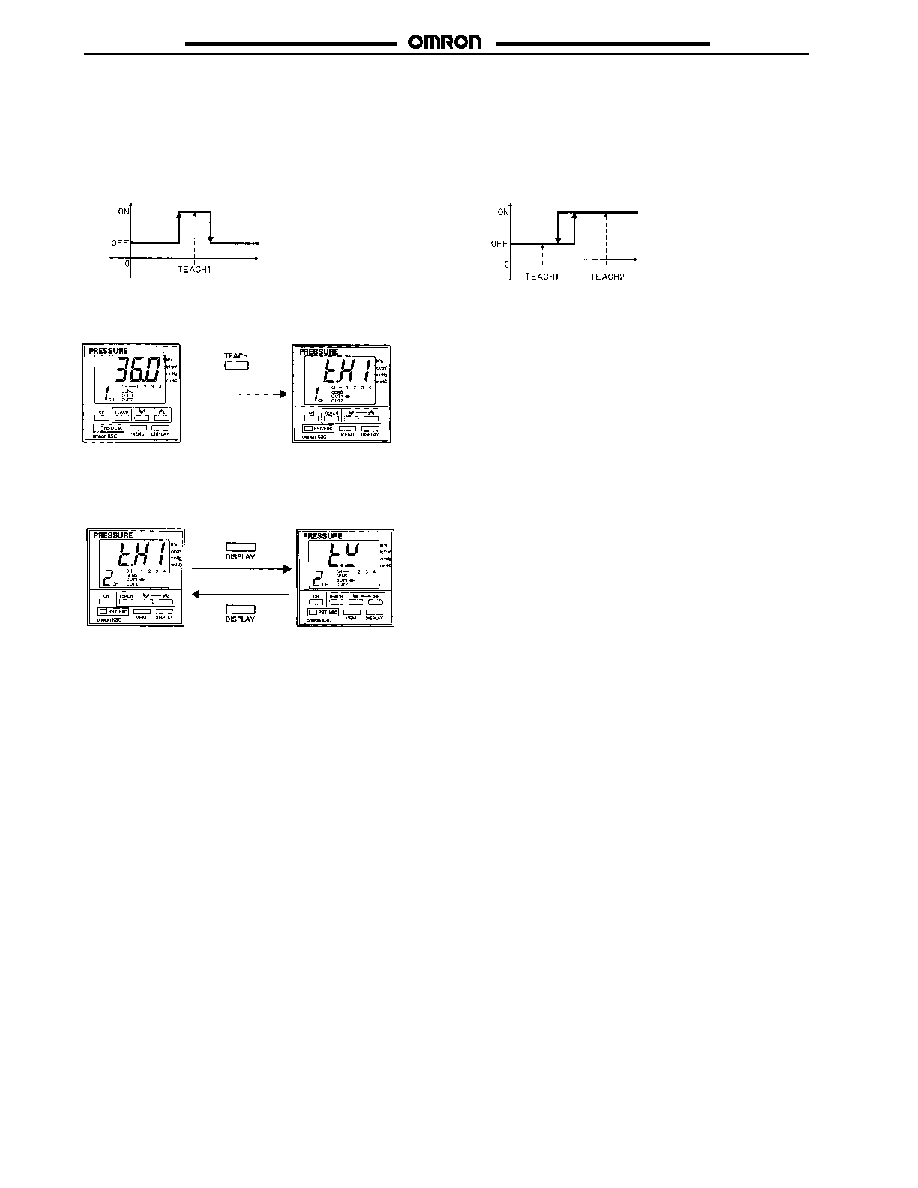
The Controller will go into teaching mode by pressing the TEACH Key for 1 s in measurement mode.
1 s
Menu Selection
Two-point teaching (i.e., hysteresis mode teaching) or one-point teaching (i.e., window mode teaching) can be selected by pressing the DIS-
PLAY Key.
By pressing the DISPLAY Key again, OUT2 will be ready for setting for channel 1 only.
Two-point teaching mode
(hysteresis mode teaching)
One-point teaching mode
(window mode teaching)
Displayed items:
TH1 (teach hysteresis mode, first point)
TW (teach window mode)

E8M/E8MS
E8M/E8MS
19
Two-point Teaching (Hysteresis Mode Teaching)
1. By pressing the TEACH Key at the point of status 1 as shown below, the present measurement value of the selected channel will
appear.
2. Check the measurement value and press the TEACH Key for teaching. Teaching will be completed on the first point.
3. By pressing the TEACH Key at the point of status 2 as shown below, the present measurement value will appear.
Two-point Teaching
ON point = (Teach 1 + Teach 2) � 2
OFF point = ON point -- 3% FS
Default is 3% FS (can be changed).
The value of teach 1
can be larger than that
of teach 2 and vice
versa. The teach 1 and
2 positions are
reversible.
Pressure
OFF point ON point
Status 1
Status 2
Ou
tp
u
t
4. Check the measurement value and press the TEACH Key for teaching. Teaching will be completed on the second point.
5. Press the RST/ESC Key so that the Controller will be in measurement mode.
Note: The Controller will be in hysteresis mode automatically after two-point teaching.
The above settings are useful for applications that check vacuum absorption.
Present
measurement value
appears.
Teaching completed
on the second point.
Teaching completed
on the first point.
Measurement mode
Present
measurement value
appears.
ON-point and
OFF-point indicators
flash.
E8M/E8MS
E8M/E8MS
20
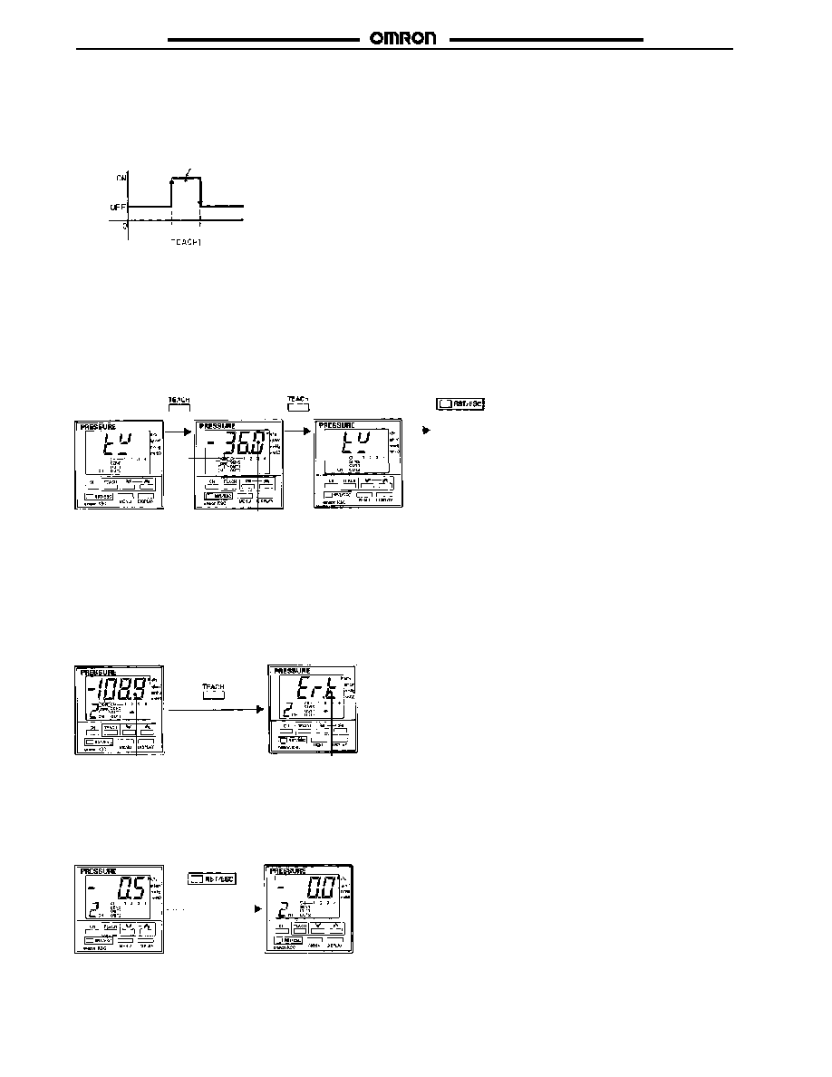
One-point Teaching (Window Mode Teaching)
1. By pressing the TEACH Key at the point of status 3 as shown below, the present measurement value will appear and ON- and OFF-
point indicators will start flashing.
One-point Teaching
ON point = Teach 1 -- 30% FS
OFF point = Teach 1 + 30% FS
Default is 10% FS (can be changed).
Status 3
Ou
tp
u
t
Pressure
ON point OFF point
2. Check the measurement value and press the TEACH Key for teaching. Teaching will be completed on the ON and OFF points.
3. Press the RST/ESC Key so that the Controller will be in measurement mode.
Note: The Controller will be in window mode automatically after one-point teaching.
The above settings are useful for applications that check original pressures.
ON-point and
OFF-point indicators
flash.
Present
measurement
value appears.
Measurement mode
Teaching completed.
ON- and OFF-point Set Values
Refer to Set Value Check on page 17 to check ON- and OFF-point set values.
Teaching Errors
Teaching will not be performed by pressing the TEACH Key if the present value or the result of teaching is not within the proper setting
range, in which case, "ER.T" (error teach) will appear for 1 s.
The present value is not within
the proper setting range.
"ER.T" (error teach)
appears for 1 s.
Measurement Value Zero-reset
Note: The Controller can be zero-reset provided that the Sensor is exposed to atmospheric pressure.
The present measurement value will be reset as zero by pressing the RST/ESC Key for 1 s. The possible zero-reset range is within �5%
FS of the rated output. Otherwise, "ER.T" will appear and the present measurement value will not be reset.
Press the RST/ESC
Key for 1 s.
E8M/E8MS
E8M/E8MS
21
J
ADVANCED OPERATIONS (SPECIAL SETTING MODE)
The Controller in this mode allows the use of versatile functions for data protection, data copying, and fine setting adjustments.
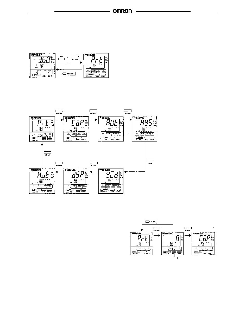
Changing to Special Setting Mode
The Controller in measurement mode will be in special setting mode if the MENU Key is pressed while the Up Key is pressed.
Measurement Mode
Special Set Mode
Menu Selection
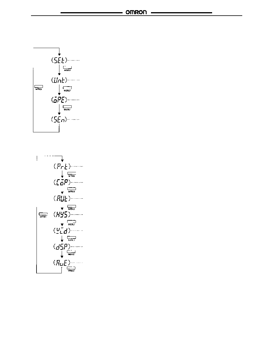
When PRT is displayed, press the MENU Key. "COP" will appear. Select the menu to be set. The display will change to "PRT," "COP," "AUT,"
"HYS," "WID," "DSP," and "AVE" in sequence by repeatedly pressing the MENU Key (refer to page 10).
The Controller will be in measurement mode by pressing the RST/ESC Key regardless of the menu selected.
Key-protect
Function
Copy Function
Original Fluctua-
tion Compensa-
tion Function
Hysteresis
Width Change
Function
Number of Times
Setting for Mea-
surement Value
Averaging
Measurement
Value Display
Refresh Interval
Setting
Window Width
Setting
Key-protect Settings
1. The protect set value will appear by pressing the DISPLAY
Key.
2. Press the Up or Down Key to change the set value.
3. The set value will be entered and "COP" will appear by
pressing the MENU Key.
If the RST/ESC Key is pressed, set value change will not be
entered and "PRT" will appear.
Key-protect Status
0: No key protect
1: No key protect in SET, UNT, zero-reset, or teaching operation,
zero-reset, and all set modes.
2: Key protect in teaching operation.
Cancel
Use the Up
or Down Key.
Edit
E8M/E8MS
E8M/E8MS
22
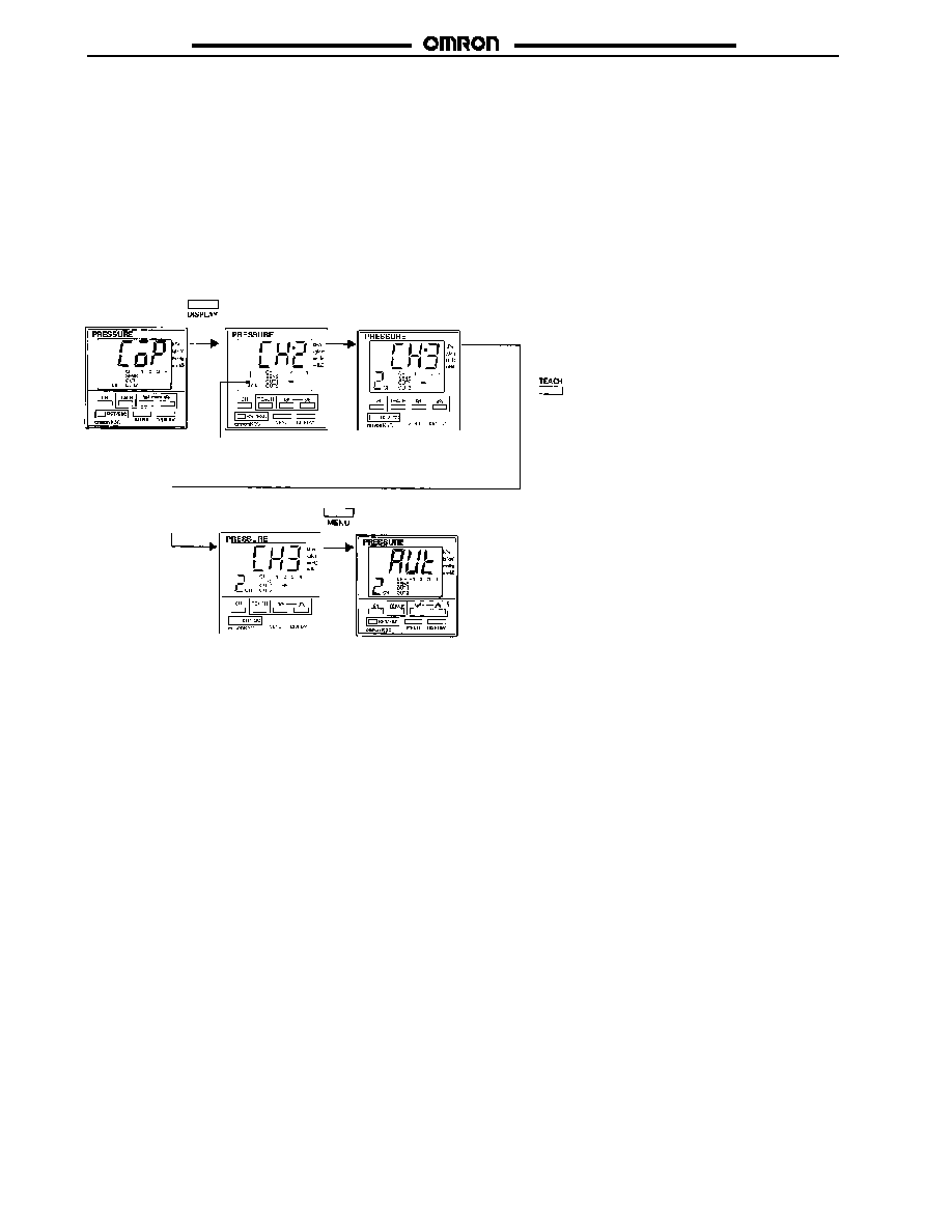
Set Value Channel-to-channel Copy
Data set in a channel can be copied and used for other channels.
1. Press the DISPLAY Key, and the source channel that has
data to be copied will appear on the main display with the
destination channel.
2. Press the Up or Down Key to select the source channel.
3. Select the destination channel with the CH Key.
4. Press the TEACH Key to copy the data.
Note: When using the K3C-MP8-T1Z 4-channel model, the OUT2 data on channel 1 will be ignored if the contents of channel 1 are co-
pied to channels 2 through 4. If the contents of channels 2, 3, or 4 are copied to channel 1, there will be no difference in data be-
tween OUT1 and OUT2 of channel 1.
Execute copy
Copying
Source channel
appears.
Source channel change
with the Up or Down Key.
Destination channel appears.
Destination channel
change with the CH Key.
E8M/E8MS
E8M/E8MS
23
Automatic Compensation of Set Value for Original Pressure Fluctuation
When using the K3C-MP8-T1Z 4-channel model, the set values on channels 2 through 4 can be compensated according to the original
pressure fluctuation that is input to channel 1. When using the K3C-DP8-TIZ 2-channel model, the CH2 setting can be compensated.
Compensation value = Original pressure fluctuation (%) x compensation coefficient
Compensation is performed every minute by comparing the one-minute mean value and reference value of the original pressure.
The reference value is the mid-value between the ON- and OFF-points of OUT 1 on channel 1.
1. The compensation coefficient will appear by pressing the DISPLAY Key.
2. Select the channel for value compensation.
3. On the basis of no compensation as 0 times, change the compensation coefficient with the Up or Down Key within a range between 0
to 10 times.
4. The compensation coefficient is entered and "HYS" will appear by pressing the MENU Key.
If the RST/ESC Key is pressed after a compensation coefficient change, the new compensation coefficient will be canceled and "AUT"
will appears.
Note: 1. Channel 1 will be skipped in the original pressure compensation menu.
2. When using the K3C-DP8-TIZ 2-channel model, the compensation coefficient setting is common to OUT1 and OUT2.
Cancel
Enter
Channel selection
with the CH Key.
Compensation coefficient change
with the Up or Down Key.
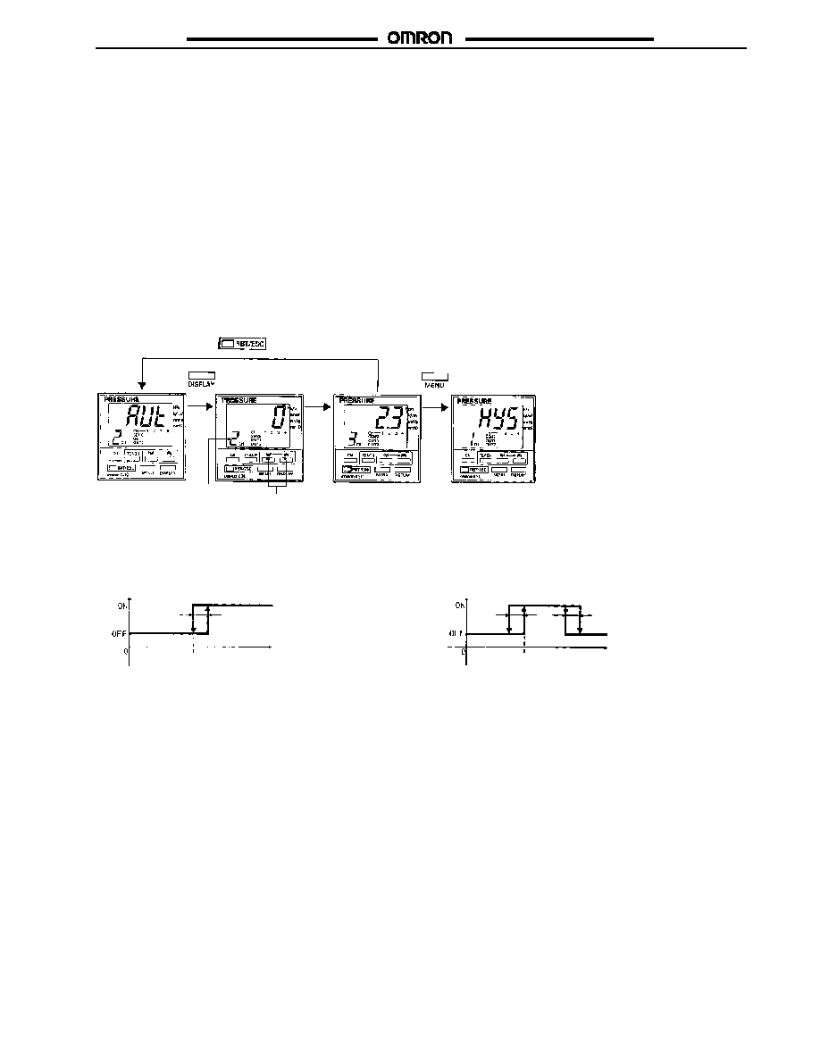
Hysteresis Width Change
Hysteresis width change is possible as shown below.
Hysteresis Mode
Window Mode
Ou
tp
u
t
OFF point ON point
Changinghysteresis
width
Pressure
Ou
tp
u
t
OFF point
ON point
Changinghysteresis
width
Pressure
1. The hysteresis width set value will appear by pressing the DISPLAY Key.
2. Select the channel where hysteresis width change is required with the CH Key.
3. Press the Up or Down Key to change the set value within a range between 0.1% and 10.0% FS.
4. The set value will be entered and "WID" will appear by pressing the MENU Key.
If the RST/ESC Key is pressed, set value change will be canceled and "HYS" will appear.
Note: 1. The above settings in hysteresis mode will be invalid if data is set in the menu while "SET" is displayed. The above settings in
hysteresis mode will be valid only if data is set by teaching. The above settings in window mode are valid in measurement
mode.
2. The width between the ON and OFF points are used as the hysteresis width in hysteresis mode. Therefore, the settings cannot
be changed in the above steps.
3. By pressing the DISPLAY Key after OUT1 is displayed, the display will change to OUT2 only with the channel that has OUT2
output.
E8M/E8MS
E8M/E8MS
24
Cancel
Enter
Channel selection
with the CH Key.
Value change with
the Up or Down Key.
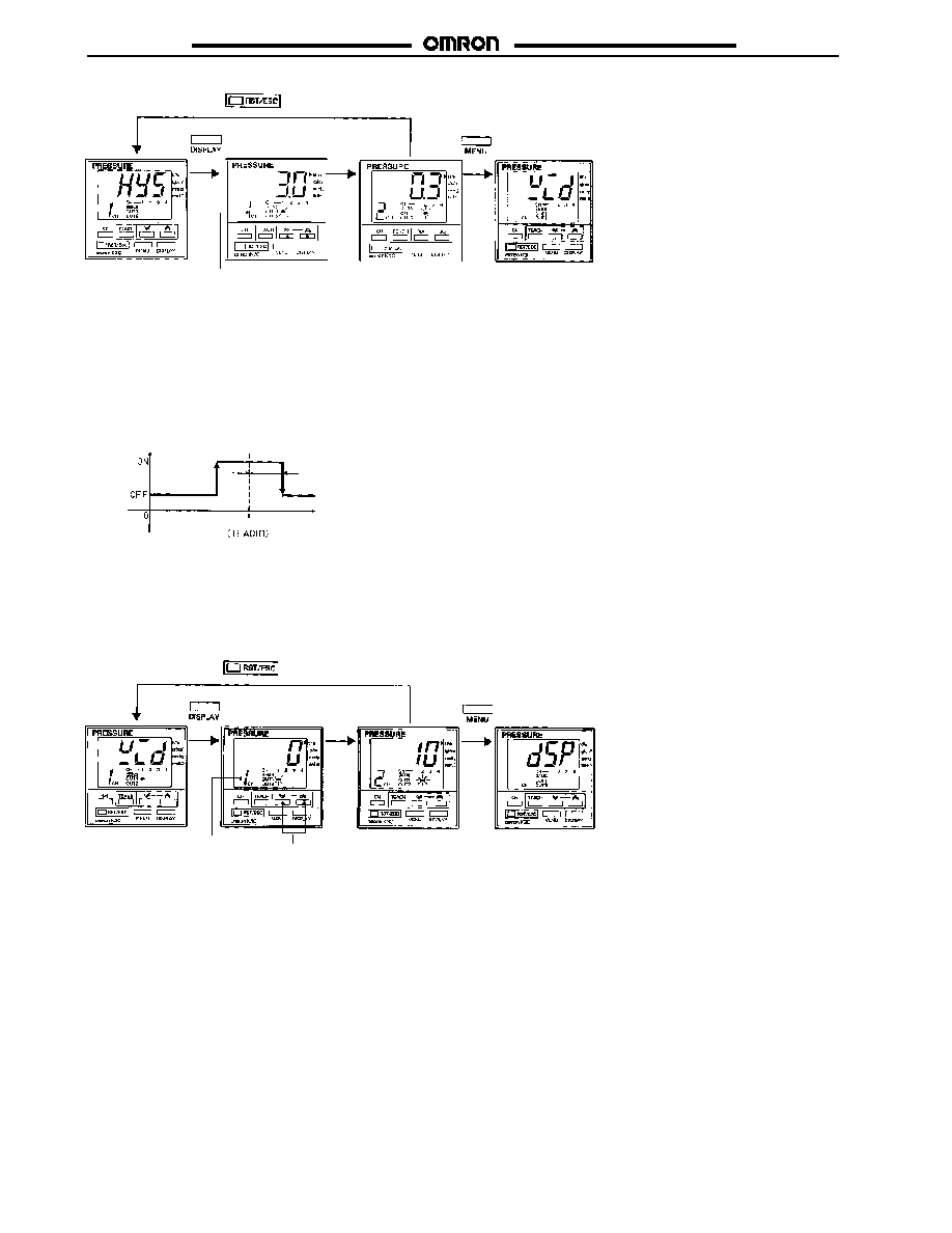
Window Width Change (Valid Only with One-point Teaching in Window Mode)
1. The window width set value will appear by pressing the DISPLAY Key.
2. Select the channel where hysteresis width change is required with the CH Key.
3. Press the Up or Down Key to change the set value within a range between 0% and 30% FS of the reference value as shown in the
following graph.
Note: Setting to 0% FS will disable ON/OFF operation.
Ou
tp
u
t
Pressure
Referencevalue
(0 to 30 %)
4. The set value is entered and "DSP" will appear by pressing the MENU Key.
If the RST/ESC Key is pressed, set value change will be canceled and "WID" will appear.
Note: 1. The above settings will be invalid if the Controller is used in hysteresis mode.
2. By pressing the DISPLAY Key after OUT1 is displayed, the display will change to OUT2 only with the channel that has OUT2
output.
Cancel
Enter
Channel selection
with the CH Key.
Value change with
the Up or Down Key.
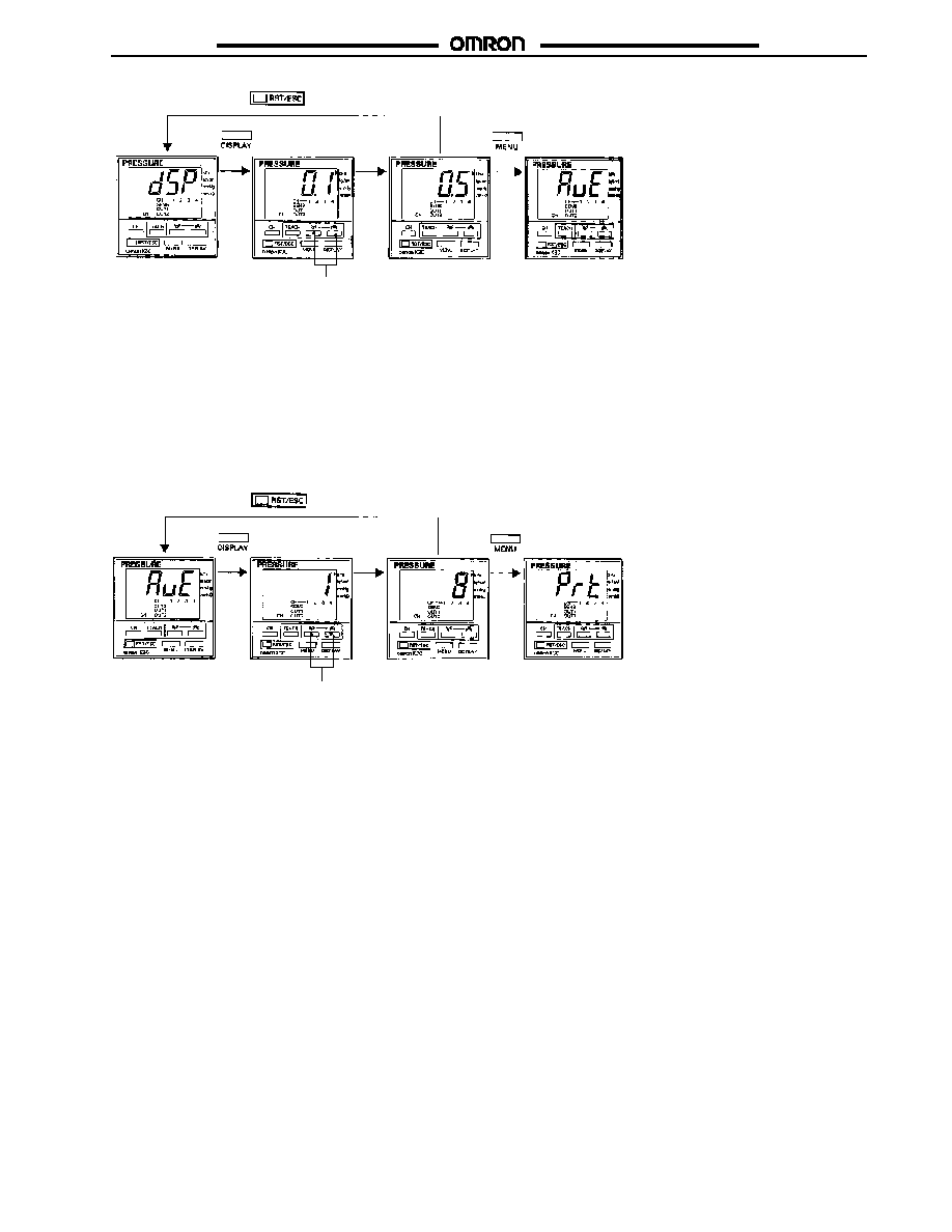
Measurement Value Display Refresh Interval Change
One of the following refresh intervals can be selected.
0.1:
Measurement values are averaged and refreshed every 0.1 s.
0.5:
Measurement values are averaged and refreshed every 0.5 s.
1.0:
Measurement values are averaged and refreshed every 1 s.
1. The display refresh interval set value will appear by pressing the DISPLAY Key.
2. Press the Up or Down Key to change the set value.
3. The set value will be entered and "AVE" will appear by pressing the MENU Key.
If the RST/ESC Key is pressed, set value change will be canceled and "DSP" will appear.
Note: The number of measurement times for measurement value averaging is set in the menu while "AVE" is displayed.
E8M/E8MS
E8M/E8MS
25
Cancel
Enter
Value change with
the Up or Down Key.
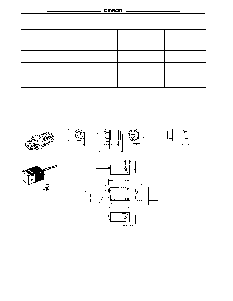
Number of Measurement Times Setting Change for Measurement Value Averaging
One of the following number of times can be selected: 1, 8, 32, and 256
1. The number of measurement times set value will appear by pressing the DISPLAY Key.
2. Press the Up or Down Key to change the set value.
3. The set value will be entered and "PRT" will appear by pressing the MENU Key.
If the RST/ESC Key is pressed, set value change will be canceled and "AVE" will appear.
Note: If 0.5 is set while "DSP" is displayed and 32 is set while "AVE" is displayed, pressure will be measured 32 times and averaged as a
block. The averaged blocks as a mean value will be displayed and refreshed every 0.5 s.
Cancel
Enter
Value change with
the Up or Down Key.
E8M/E8MS
E8M/E8MS
26
J
ERROR DISPLAY
Contents
Display
Error code
Reset method
Output (OUT1, OUT2)
Sensor error
Error code flashes.
err
Reset the power supply.
All OFF
Input lower limit
error
Flashes at the lower limit.
(Corresponding sensor indicator
flashes.)
None
Automatically reset when the
input returns to the specified
range.
Normal operation
Input upper limit
error
Flashes at the upper limit.
(Corresponding sensor indicator
flashes.)
None
Automatically reset when the
input returns to the specified
range.
Normal operation
Output load
short-circuiting
Output indicator flashes.
None
Automatically reset when the
short-circuit is removed.
Only the corresponding
channel flashes.
Teaching input
range error
Error code flashes.
er.t
Not registered. (Error is
displayed for one second.)
All OFF during teaching.
Zero reset range
error
Error code flashes.
er.0
Not registered. (Error is
displayed for one second.)
Normal operation
Dimensions
Unit: mm (inch)
J
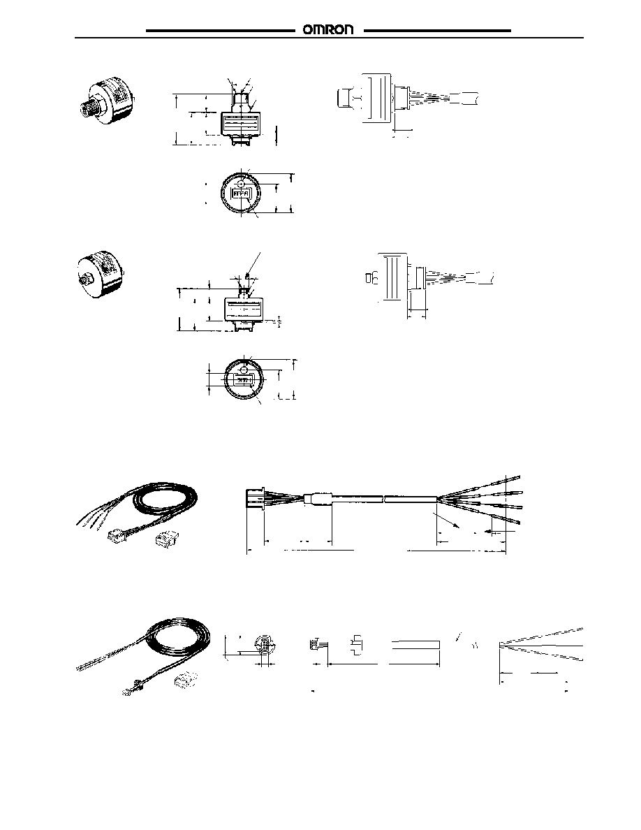
SENSORS
E8MS-01
E8MS-10
E8MS-N0
M5, 7.5-mmdepth
Pressure joint
Connector:DF13B-3P-1.25V(21)
by Hirose Electric
12 dia.
(0.47 dia.)
Connection with E89-M4
Sensor I/O Connector
15
(0.59)
13
(0.51)
29.7 (1.17)
8.5
(0.33)
32.5 (1.28)
1/8 NPT
8.8
(0.35)
5.3
(0.21)
10
(0.39)
13.4
(0.53)
5
(0.20)
3.4
(0.13)
5.4
(0.21)
5.3
(0.21)
E8M-A1
Power indicator
M5, 7-mm-deep pressure joint
(Negative)
4-mm-dia., 4-conductor
(40 strands x 0.08 dia.),
vinyl-insulated cord,
length: 3 m
Two, M4
mounting hole
M5, 7-mm-deep pressure joint (Positive)
26
(1.02)
8
(0.31)
8.4
(0.33)
42.9 (1.69)
39 (1.54)
19
(0.75)
20�0.1
(0.79�0.004)
20
(0.79) 9 (0.35)
42.5 (1.67)
3
(0.12)
8.4
(0.33)
8
(0.31)
E8M/E8MS
E8M/E8MS
27
E8M-10
Pressure
joint
Power indicator
4.9 (0.19) dia.
B04B-XASK Connector
M8 hexagonal nut
37.5
(1.48)
24
(0.94)
27.5
(1.08) dia.
13
(0.51)
Connection with E89-M3 Sensor I/O Connector
13.5
(0.53)
16.7
(0.66)
M5
9.2
(0.36)
20.6
(0.81)
1.4
(0.06)
8.2
(0.32)
10
(0.39)
1/8 NPT
E8M-N0
Pressure
joint
B04B-XASK Connector
M4 hexagonal nut
27.5
(1.08) dia.
31
(1.22)
24
(0.94)
7
(0.28)
Connection with E89-M3 Sensor I/O Connector
8.2
(0.32)
10
(0.39)
M5
1.4
(0.06)
16.7
(0.66)
9.2
(0.36)
20.6
(0.81)
7 (0.28)
Power indicator
4.9 (0.19) dia.
E89-M3 Sensor I/O Connector Cable for E8M
(Sold separately) Includes one XS8A-0442 cable Connector.
3000 (118.11)
30
(1.18)
30
(1.18)
20
(0.79)
(0.39)
10
50 (1.97)
E89-M4 Sensor I/O Connector Cable for E8MS
(Sold separately) Includes one XS8A-0442 cable Connector.
2.9-mm-dia. (0.15/0.9 dia.), 3-con-
ductor vinyl-insulated round cable;
length: 3 m
3000
(118.11)
30
(1.18)
3.2
(0.13)
8.9
(0.35)
5.4
(0.21)
4
(0.16)
50
(1.97)
50 (1.97)
10
(0.39)
E8M/E8MS
E8M/E8MS
28
XS8A-0442 Cable Connector (One Connector is Supplied with the E8M-A1)
16.1
(0.63)
20
(0.79)
7
(0.28)
One XS8A-0442 Cable Connector is provided with the E89-M3 and E89-M4 Sensor
Connector Cable. Refer to the Ordering Information section for replacement orders.
3.2
(0.13)
2.5
(0.10)
7
(0.28)
2.54
(0.10)
10.2
(0.40)
7.62
(0.30)
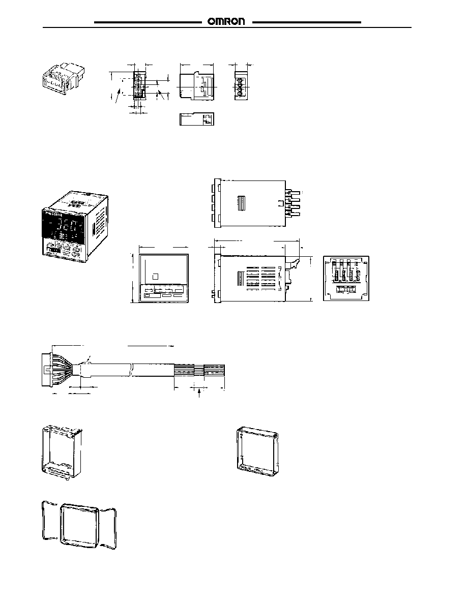
J
CONTROLLER
K3C-MP8T1Z
K32-MP2W (Power and Output Connector for K3C Controller)
(Sold Separately)
48
(1.89)
84 (3.31)
44.8
(1.76)
(78.74)
2,000
6
(0.24)
63.7 (2.51)
14.2
(0.56)
5 dia. (0.20)
5 (0.20)
10 (0.39)
(0.79)
20
(0.79)
20
10
(0.79)
20
(0.59)
15
48
(1.89)
(0.39)
Adapter (Provided with Controller)
Y92A-48F1 Soft Cover (Sold Separately)
Y92A-48 Hard Cover (Sold Separately)
Note: Protection from Water and Oil
The Controller is of a water-resistant construction which
protects the internal circuitry from water that may enter
through the space between the front panel and any key.
Use the Soft Cover, however, if the Controller is to be
operated with wet or oily hands. Although the Soft Cover
conforms to IEC IP54F, do not install the Controller with
the Soft Cover in places where oil may be directly sprayed
onto the Controller.
E8M/E8MS
E8M/E8MS
29
Installation
J
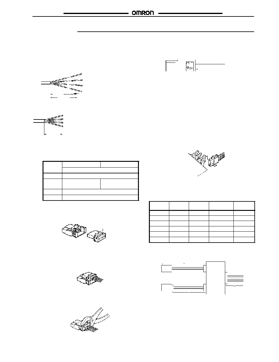
ASSEMBLY PROCEDURE
For the E89-M3/M4 Sensor I/O Connector Cable (Sold
Separately) and XS8A-0442 Cable Connector (Pro-
vided with Sensor)
1. Processing the Sensor I/O Connector Cable End
The cable end is semi-stripped.
Semi-stripped
30
(1.18)
50 (1.97)
10 (0.39)
Cut the ends as shown in the following illustration, and do not
peel the shield.
20 min
(0.79)
2. Fitting Controller Conductors to Cable Connector Cover
Terminal numbers are engraved on the cover. Refer to the
following and be sure that these terminal numbers correspond to
the wire colors correctly.
Terminal
N
E89-M4
E89-M3
Terminal
No.
I/O code
1
Black (Output)
2
---
Pink
(LED lighting input)
3
Brown (Vcc)
4
Blue (GND)
Note: Pin 2 will be empty when the E89-M4 is mounted.
Check again that the terminal numbers correspond to the wire
colors correctly. Then, insert the cover into the plug connector.
Plug connector
Terminal number
Cover
Be sure that the cover is fully inserted into the plug connector.
3. Connecting Wires to Plug Connector
Tentatively place the wired cover on the plug connector.
Press the cover and fit the wires. Pliers can be used, in which
case, apply the pliers to the middle part of the cover and press
the cover as straight as possible against the plug connector.
Be sure that there is no space between the cover and plug
connector.
No clearance allowed
Check through the window of the cover that the wires are fitted to
the plug connector properly.
Once attached to the plug connector, the cover and plug
connector cannot be reused. Before using the pliers to attach the
cover, be sure that the terminal numbers correspond to the wire
colors correctly. If the wires are connected to the plug connector
incorrectly, use a new cable connector.
4. Connecting/Disconnecting Controller Connector to/from the
K3C-MP8-T1Z Four-channel Pressure Controller
Be sure that terminal number 1 engraved on the cable connector
is facing upwards (i.e., on the lock-lever side) and press the
cable connector against the socket connector until the cable
connector snaps in place.
Lift up the lock lever before disconnecting the plug connector.
(1)
(2)
Sensor and Controller Combinations
Use the Pressure Controllers in the following combinations. The
E89-M3/M4 is required when using the Sensor as a single unit.
Model
E89-M3
E89-M4
K3C-MP8-T1Z
K3C-DP8-T1Z
K32-MP2W
E8MS-01
�
f
f
f
E8MS-10
�
f
f
f
E8MS-N0
�
f
f
f
E8M-A1
�
�
f
f
E8M-10
f
�
f
f
E8M-N0
f
�
f
f
Note:
f
: Required; �: Not required.
Sensor and Controller Connection
E8M-A1
E8MS-jj
E8M-10/N0
E89-M3/M4
K3C
S
ens
or
input
Cont
r
o
ller
out
put
K32-MP2W
E8M/E8MS
E8M/E8MS
30
Precautions
J
APPLICATIONS
You must allow sufficient leeway in ratings and performance and
provide proper fail-safe and other safety measures when using the
Link the E8M in any of the following applications. Be sure also to
consult with your OMRON representative before actually attempt-
ing any of these applications.
1. Applications under conditions or environments not specified
in the instructions sheets.
2. Applications for nuclear reactor control, train facilities, avi-
ation facilities, motorized vehicles, furnaces, medical equip-
ment, amusement equipment, and safety equipment.
3. Applications strongly related to human life or property, partic-
ularly those requiring safety.
J
WARNINGS
Environment
Do not use the Sensor in locations subject to explosive or
flammable gases.
Power Supply Voltage
Do not apply voltages in excess of the specified power supply
voltage range. Applying voltages beyond the specified range may
result in burning.
Short-circuit in Load
Do not short-circuit the load. Short-circuit the load may result in
breaking or burning.
Incorrect Wiring
Be sure to connect to the polarities of the power supply correctly
and avoid incorrect wiring. Incorrect connection or wiring may
result in breaking or burning.
J
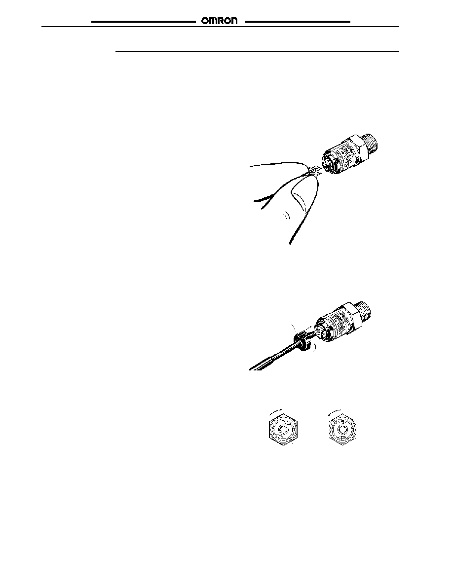
CORRECT USE
Connecting and Locking the E8MS Sensor I/O Con-
nector (E89-M4)
1. Hold both ends of the female connector connected to the
Sensor I/O Connector so that the protrusion on the female
connector faces upward, orientate the hole in the male con-
nector on the Sensor upwards, and insert the female connec-
tor into the hole until the protrusion clicks in.
2. A lock cover is slid through the Sensor I/O Connector to pre-
vent it from coming free due to vibration or shock.
Insert the lock cover facing in the correct direction (a) as
shown in the following figure, and rotate it clockwise (b) until
it clicks in.
Lock cover
(a)
(b)
3. To unlock the connector, rotate the lock cover counterclock-
wise until it clicks, then pull it towards you.
To disconnect the connector, hold both ends of the connector,
then pull it towards you.
Lock
Lock cover
Unlock
Note: Forcibly pulling the cable to disconnect the connector may
damage the pressure-welded portion. Be sure to hold both
ends of the connector when disconnecting it.

E8M/E8MS
E8M/E8MS
E8MS-jj/E8M-10
The pressure-introducing section (aluminum for E8MS, SUS304
for E8M) is fixed with tapered 1/8 NPT male screws and M5
female screws.
When using tapered screws, use tapered 1/8 NPT female
screws. Wrap the tapered 1/8 NPT male screws with sealing tape
to prevent any leakage. Tighten the male screws to a torque no
more than 3.9 N S m (2.88 ft S lbs).
Tighten M5 female screws to a torque no more than 1 to 1.5
N S m (0.74 to 1.11 ft S lbs).
When tightening a screw, hold by its hexagonal head, not by its
body.
E8M-N0
The pressure-introducing section (SUS304) is fixed with M5 male
screws.
Tighten male screws to a torque no more than 1 to 1.5 N S m
(0.74 to 1.11 ft S lbs).
When tightening a male screw, hold by its hexagonal head, not
by its body.
E8M-A1
The pressure-introducing section (SUS303) is fixed with M5
female screws (7 mm deep).
Tighten screws for the pressure-introducing section to a torque
no more than 1 to 1.5 N S m (0.74 to 1.11 ft S lbs).
M4 female screws are used for the product mounting sections.
When mounting the product, tighten the screws while holding a
metal part of the product, not a resin part.
Tighten the product mounting screws to a torque no more than
1.2 N S m (0.89 ft S lbs).
If the positive pressure section is released and positive pressure
is applied to the negative pressure section, a positive pressure
may be displayed.
All Models
Do not use the Sensor in an environment subject to corrosive or
combustible gases.
Be sure to use the Sensor in an environment where air-borne
water or oil is removed by air filters.
Do not use the Sensor alongside a high-tension voltage line or
power line.
Do not expose the Sensor to water.
Mount the Sensor so that ultrasonic vibrations will not be applied
directly to the Sensor.
Be sure to use the Sensor under the rated pressure.
Do not insert any wire into the pressure sections. Doing so may
damage the pressure elements and cause a malfunction.
Do not apply any tensile strength in excess of 20N (4.5 lbs) for
E8MS, 30N (6.75 lbs) for E8M to the cables or connectors.
Do not pull the cables. When removing the connectors for
external connection, be sure to use the lock lever.
K3C
Install the Sensor horizontally.
The recommended panel thickness is 1 to 5 mm (0.04 to 0.20 in).
Do not install the Sensor in an environment subject to strong
vibration or shock.
Do not install the Sensor under dusty conditions.
Do not install the Sensor in an environment subject to corrosive
gases, particularly sulfide and ammonia gases.
Do not install the Sensor near equipment that generates strong
high-frequency noise such as high-frequency welders or sewing
machines.
Cat. No. CEDSAX4 11/01 Specifications subject to change without notice. Printed in U.S.A.
OMRON ELECTRONICS LLC
One East Commerce Drive
Schaumburg, IL 60173
NOTE: DIMENSIONS SHOWN ARE IN MILLIMETERS. To convert millimeters to inches divide by 25.4.
1-800-55-OMRON
OMRON CANADA, INC.
885 Milner Avenue
Scarborough, Ontario M1B 5V8
416-286-6465
R
OMRON ON--LINE
Global -- http://www.omron.com
USA -- http://www.omron.com/oei
Canada -- http://www.omron.com/oci