 | –≠–ª–µ–∫—Ç—Ä–æ–Ω–Ω—ã–π –∫–æ–º–ø–æ–Ω–µ–Ω—Ç: E8Y-A5C-R | –°–∫–∞—á–∞—Ç—å:  PDF PDF  ZIP ZIP |
Document Outline
- Front Page
- Ordering Information
- Specifications
- Application Examples
- Nomenclature
- Operation
- Dimensions
- Precautions
- Contacting Omron
E8Y
E8Y
2
Type
Digital output
Analog output
Pressure range
Port/Mounting
Part number
0 to 2.0 kPa
4.5 mm dia. pipe
E8Y-A2C
1/8 NPT
E8Y-A2C-R
0 to 5.0 kPa
4.5 mm dia. pipe
E8Y-A5C
1/8 NPT
E8Y-A5C-R
0 to 0.290 psi
4.5 mm dia. pipe
E8Y-A2C-D
1/8 NPT
E8Y-A2C-RD
0 to 0.725 psi
4.5 mm dia. pipe
E8Y-A5C-D
1/8 NPT
E8Y-A5C-RD
4 to 20 mA
0 to 2.0 kPa
4.5 mm dia. pipe
E8Y-A2Y
1/8 NPT
E8Y-A2Y-R
0 to 5.0 kPa
4.5 mm dia. pipe
E8Y-A5Y
1/8 NPT
E8Y-A5Y-R
0 to 0.290 psi
4.5 mm dia. pipe
E8Y-A2Y-D
1/8 NPT
E8Y-A2Y-RD
0 to 0.725 psi
4.5 mm dia. pipe
E8Y-A5Y-D
1/8 NPT
E8Y-A5Y-RD
Flow sensor
--
1/8 NPT, vertical
E8Y-A5C-F03V
1/8 NPT, horizontal
E8Y-A5C-F03H
1/8 NPT, vertical
E8Y-A5C-F20V
1/8 NPT, horizontal
E8Y-A5C-F20H
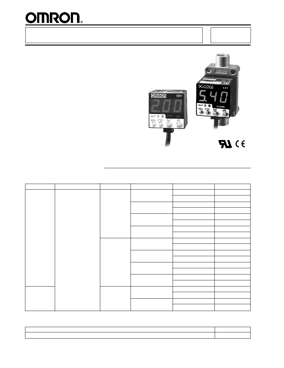
"Cube" Type Differential Pressure
Sensor with LED Display Offers High
Precision Sensing
s
New
psi version available
s
Compact, cube-style measuring 31 x 30
x 30 mm (1.22 x 1.18 x 1.18 in) saves
mounting space
s
Easy-to-read red LEDs
s
Digital and analog output available
s
Flow sensing type available
s
PNP output types available upon special
request
Ordering Information
Differential Pressure Sensor
E8Y
s
SENSOR
s
ACCESSORIES
Description
Part number
Panel-mounting bracket
E89-Y1
Miniature
differential
pressure
sensor
NPN open collector
(2 independent outputs)
--
0.3 to 3.0 liter/min.
(0.07 to 0.68 gal./min.)
2.0 to 20 liter/min.
(0.45 to 4.54 gal./min.)
E8Y
E8Y
3
Item
E8Y-A2C
E8Y-A5C
E8Y-A2Y
E8Y-A5Y
E8Y-A5C-F03V
E8Y-A5Y-F20V
E8Y-A2C-R
E8Y-A5C-R
E8Y-A2Y-R
E8Y-A5Y-R
E8Y-A5C-F03H
E8Y-A5Y-F20H
E8Y-A2C-D
E8Y-A5C-D
E8Y-A2Y-D
E8Y-A5Y-D
E8Y-A2C-RD
E8Y-A5C-RD
E8Y-A2Y-RD
E8Y-A5Y-RD
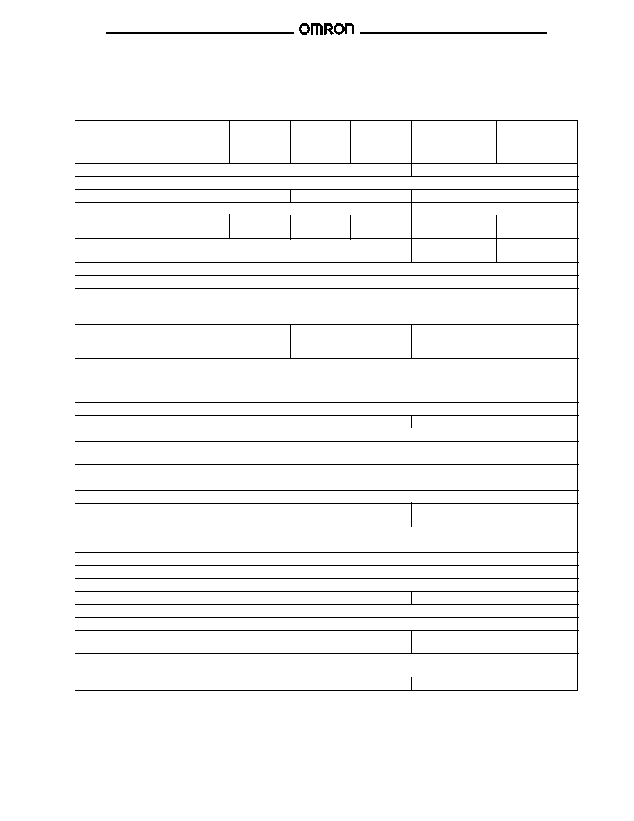
Sensor type
Differential pressure sensor
Flow sensor
Power supply voltage
12 to 24 VDC
±
10%, ripple (p-p) 10% max.
Current consumption
50 mA max.
75 mA max.
50 mA max.
Pressure type
Differential pressure
Differential pressure sensing
Rated pressure /
0 to 2.0 kPa
0 to 5.0 kPa
0 to 2.0 kPa
0 to 5.0 kPa
0.3 to 3.0 L/min.
2.0 to 20.0 L/min.
volume range
0 to 0.29 psi
0 to 0.73 psi
0 to 0.29 psi
0 to 0.73 psi
0.068 to 0.68 gal/min.
0.45 to 4.54 gal/min.
Withstand pressure /
50 kPa (7.25 psi)
5 L/min (1.14 gal)
40 L/min (9.08 gal)
volume
Applicable fluid
Non-corrosive gas and non-flammable gas
Accuracy
±
3% FS max.
Linearity
±
1% FS max.
Responce time
±
0.5 sec max.
(digital output)
Linear output
--
4 to 20 mA
±
1%FS with a
--
permissible resistive load
of 250
Digital output
NPN open collector (NO/NC)
Load current: 100 mA max.
Applied voltage: 30 VDC max.
Residual voltage: 1 V max. with a load current of 100 mA or 0.4 V max. with a load current of 16 mA
Display
3 digit red LED; the orange LED indicator is lit for two independent outputs.
Display accuracy
±
1% FS
±
3% FS
Circuit protection
Reverse polarity connection, load short-circuiting
Ambient temperature
Operating: -10
∞
C to 55
∞
C (14
∞
F to 131
∞
F) with no icing
Storage: -25
∞
C to 65
∞
C (-13
∞
F to 149
∞
F)
Ambient humidity
Operating: 25% to 85% (with no condensation)
Temperature influence
±
3% FS max.
Voltage influence
±
1.5% FS max.
Setting resolution
0.01 kPa
0.001 psi
0.0 1L/min.
0.1 L/min.
Insulation resistance
100 M
(at 500 VDC) between current-carry parts and case
Dielectic strength
1,000 VAC 50/60 Hz at 1 min.
Vibration resistance
Endurance: 10 to 500 Hz, 1.0-mm double amplitude or 150 m/s
2
, 3 times each for 11 min. in X, Y and Z directions
Shock resistance
Endurance: 300 m/s
2
(30G) 3 times each to X,Y and Z directions
Degree of protection
IEC60529, IP40
Pressure port
NPT 1/8 female screw or 4.5 dia. pipe
1/8 NPT female screw
Connection method
Pre-wired (standard length: 2 m)
Cable
Approved by UL
Weight
Approx. 80 g (2.8 oz)
Approx. 160 g (5.6 oz)
(including packing material)
(including packing material)
Material
Pressure port: resin pipe for 4.5 dia., zinc die-cast for 1/8 NPT taper screw
Case: heat-resistant PBT
Accessories
Mounting bracket and instruction sheet
Instruction sheet
Specifications
s
RATINGS/CHARACTERISTICS
E8Y
E8Y
4
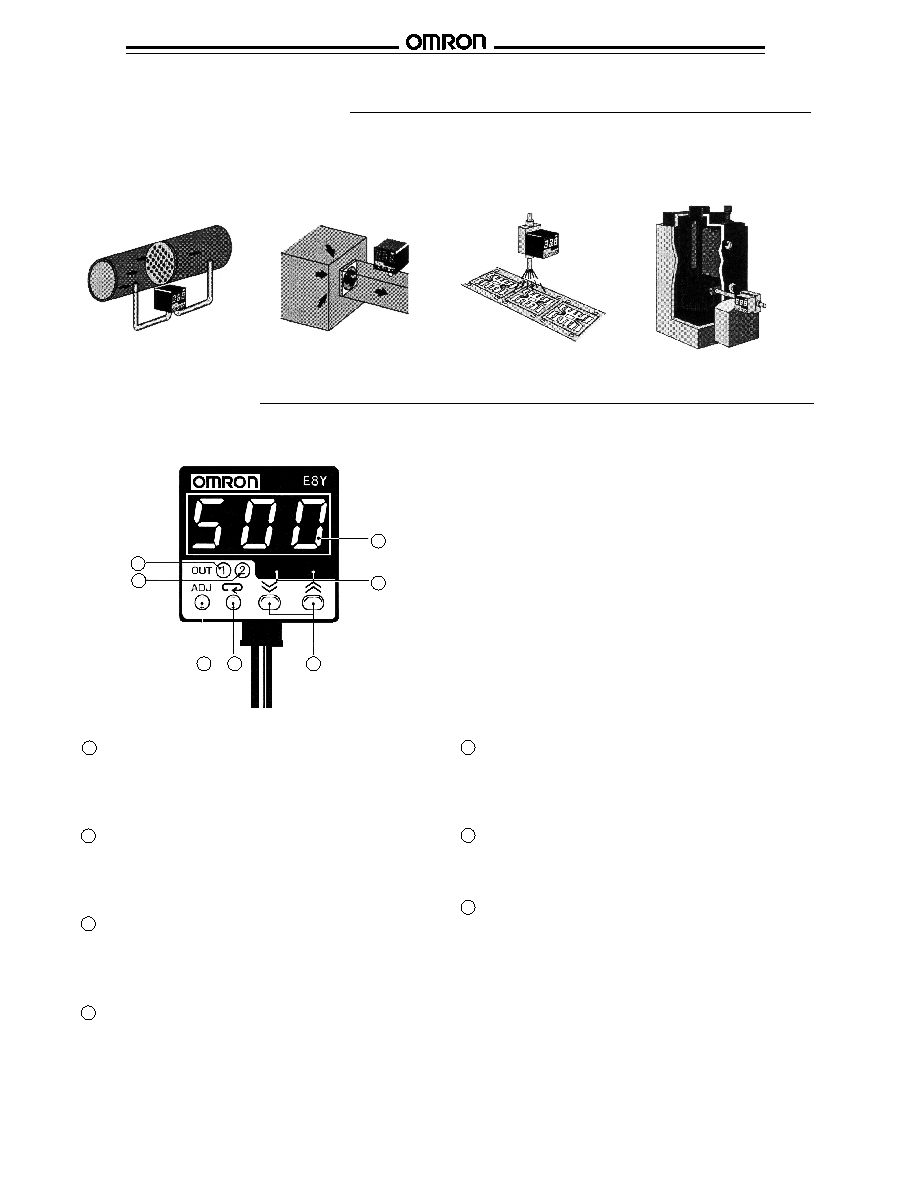
Nomenclature
s
E8Y PRESSURE SENSOR
Display
1 Numerical value/menu indication
Displays the measured pressure and some menu
settings.
2 Unit
Shows the measuring unit. Unit currently in use is
illuminated.
3 OUT 1 indication LED
In measurement mode, it lights when OUT 1 output is on.
In setting mode, it flashes when OUT 1 is being set.
4 OUT 2 indication LED
In measurement mode, it lights when OUT 2 output is on.
In setting mode, it flashes when OUT 2 is being set.
Operation key
5 ADJ
In measurement mode, it adjusts the Zero Point. In
setting mode, it shifts to measurement mode.
6 MODE
Selects the current number setting or menu option.
7 UP/DOWN
In measurement mode, pushing the DOWN key displays
the ON and OFF points of OUT 1; pushing the UP key
displays the ON and OFF points of OUT 2. In setting
mode, the UP and DOWN keys increase or decrease the
numeric value, respectively, or scroll through the menu
options.
1
2
3
4
5
6
7
Application Examples
Filter
E8Y
E8Y
E8Y-
-F
N
2
Lead Frame
E8Y-
-F
s
DETECTION OF
FILTER
CLOGGING
s
EXHAUST FAN
ROTATION
DETECTION
s
DETECTION OF
FLOW
s
AIR FLOW
CONTROL
x10-
3
psi

E8Y
E8Y
5
s
FUNCTIONS
Operation
Function
Description
Pressure units
Switches between mmH2O and kPa, excluding the E8Y- -F flow sensor.
switching
Comparitive ON/
Two independent outputs can be set.
OFF output (two
(1) Output mode (mode is automatically determined from the ON and OFF point set values.)
independent
Hysteresis mode:
outputs
If ON point point set value > OFF point set value
For normal open:
For normal close:
Window mode:
If ON point set value < OFF point set value
For normal open:
For normal close:
(2) Setting mode
ON point / OFF point: Each output can be set in the range from 0 to the rated value. Set value: 0 to rated value
Output configuration:
Each output can be set as normally open (NO) or normally closed (NC).
Setting: NO <> NC
Hysteresis:
Each output can be set at 10% of the range from 0 to the rated value. (Effective in
window mode and 2-point auto-teaching mode.) Setting range: (0 to rated value) x 10%
Auto-teaching
When the auto-teaching mode is used, measured values can be input as ON point or OFF point set values
instead of key inputs. Two types of auto-teaching are available: 1-point auto-teaching, where only one single
point is set, and 2-point auto-teaching, where two points are set.
(1) 2-point auto-teaching (Hysteresis mode teaching)
This function automatically sets the ON point and OFF point for the comparative output by designating a point
with no object (TEACH 1) and a point with an object (TEACH 2) using actual objects. The outputs are made in
hysteresis mode. The hysteresis is a set value.
The set value is the mid-point between TEACH 1 and TEACH 2.
Example: If TEACH 1 is 0.25 kPa and TEACH 2 is 0.95 kPa, the ON point set value = (0.95+0.25)/2 = 0.60
(This table continues on the next page)
0
Output
ON
OFF
OFF set value ON set value
Pressure value
0
Output
ON
OFF
OFF set value
ON set value
Pressure value
Hysteresis width
(set value)
Output
ON
OFF
OFF set value ON set value
Pressure value
Hysteresis width
(set value)
Output
ON
OFF
OFF set value
ON set value
Pressure value
Hysteresis width
(set value)
Hysteresis width
(set value)
0
Output
ON
OFF
OFF
point
Pressure value
ON
point
Hysteresis width
Set value
TEACH 1
TEACH 2
E8Y
E8Y
6
Functions Table - continued from previous page
Function
Description
Auto-teaching
(2) 1-point auto-teaching (Window mode teaching)
(continued)
This function automatically sets the ON point and OFF point for the comparitive output by inputing a reference
point (TEACH 1) using an actual object. The function operates only when an object exists. The outputs are
made in the window mode. The hysteresis width and window width are set values. (The window width set value
is valid only when 1-point teaching is set. Setting range: (0 to rated value) x 30%)
The ON point and OFF point set values are set at the reference point
±
window width.
Example: If the reference point (TEACH 1) is 0.90 kPa and the window width is 0.50 kPa,
the ON set value = (0.90 - 0.50)/2 = 0.20 and the OFF point set value = (0.90+0.50)/2 = 0.70.
Key-protect
This function restricts switch operation to prevent the set value from being easily changed.
(Set value lock
Set value: OFF <> ON
function)
Set value
Hold down the ADJ key for several seconds in the measurement mode to activate this function.
zero-setting
Speed control
Select from three values of display speed for the measured pressure values. Set value: 0.1 s, 0.5 s, 1.0 s
function with
measured
pressure display
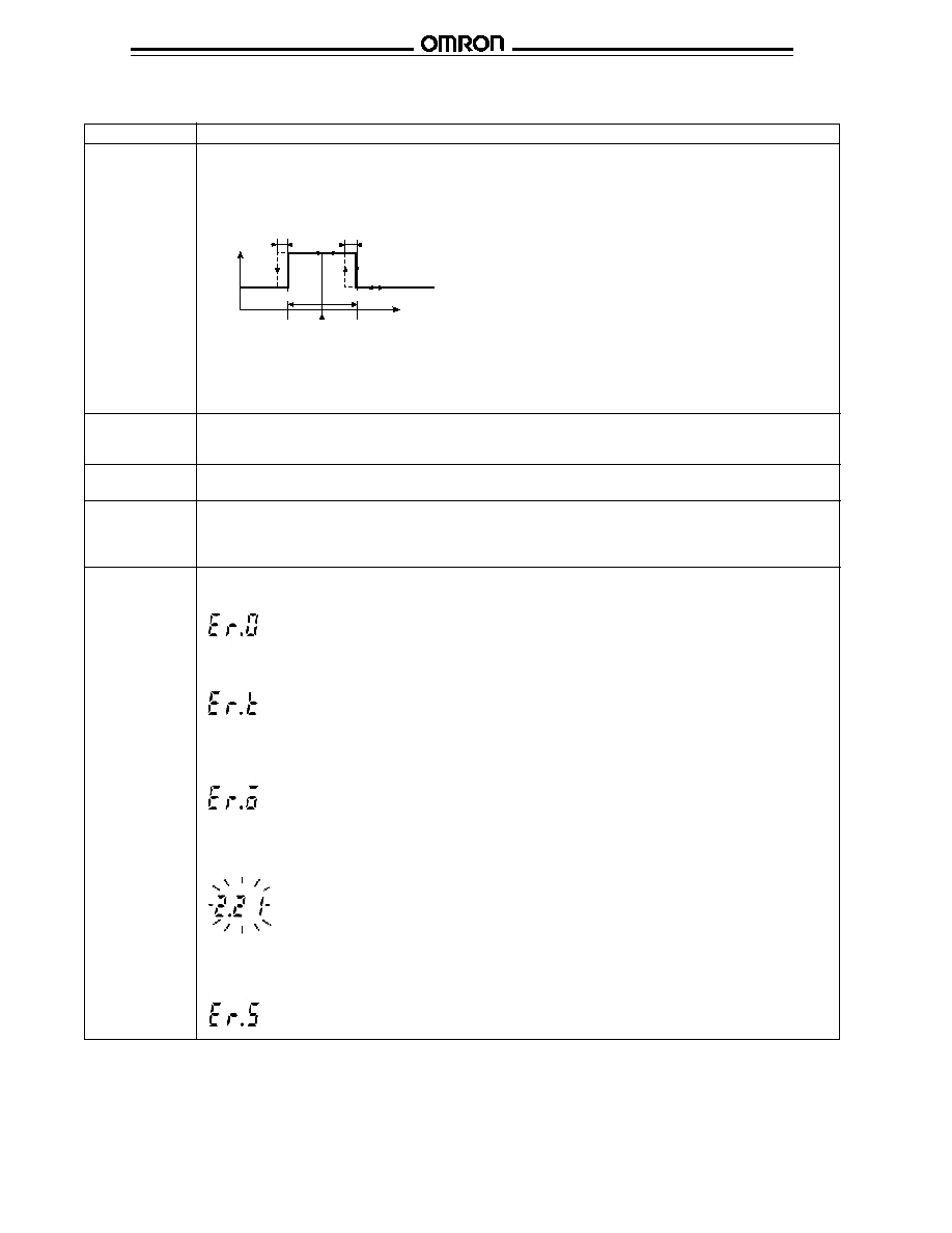
Error display
(1) Pressure warning during zeroing:
Error display and warning if excess pressure or flow (exceeding rated value
±
5%) is applied during zeroing.
(2) Teaching error display:
Warning if teaching is unsuccessful.
(3) Short-circuit protection and display:
If overcurrent flows in a connected load, the abnormal status is notified by an error display and the OUT LED,
for the corresponding output, flashing. Transistor acts to cut the abnormal current.
(4) Abnormal pressure or flow detection:
The diplayed value flashes to indicate the abnormal status if the applied pressure or flow exceeds the rated
value by 10%. This error is automatically reset when the supplied value enters the rated range.
(5) ON/OFF point input error warning:
Indicates if the difference between the ON point and OFF point in the window mode exceeds the hysteresis
value + setting resolution (0.01 kPa/1 mmH
2
O).
0
Output
ON
OFF
OFF
point
Pressure value
ON
point
Hysteresis width
(TEACH 1)
Hysteresis width
Window width
Standard
value
Window width

E8Y
E8Y
7
s
OUTPUT CIRCUIT DIAGRAM
s
WIRING
Color
Comparison output type
Linear output type
Brown
Power supply 12 to 24 V
Power supply 12 to 24 V
Blue
0 V
0 V
Black
Comparison output 1
Comparison output 1
White
Comparison output 2
Comparison output 2
Gray
--
Linear output
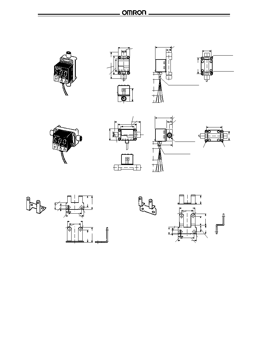
Dimensions
Unit: mm (inch)
s
CONTROLLER OF PRESSURE SENSOR
Standard Port (Pressure Port 4.5 dia.) Type
E8Y-A2C
E8Y-A5C
E8Y-A2Y
E8Y-A5Y
E8Y-A2C-D
E8Y-A5C-D
E8Y-A2Y-D
E8Y-A5Y-D
Die-cast Port (Pressure Port Rc(PT) 1/8) Type
E8Y-A2C-R
E8Y-A5C-R
E8Y-A2Y-R
E8Y-A5Y-R
E8Y-A2C-RD
E8Y-A5C-RD
E8Y-A2Y-RD
E8Y-A5Y-RD
4.5 dia.
pressure port (-)
18
(0.71)
22 (0.87)
15 (0.59)
31 (1.22)
30
(1.18)
5 (0.20)
29.8
±
0.6
(1.17
±
0.02)
39.8 (1.57)
10
(0.39)
4.5 dia.
pressure port (+)
22
(0.87)
Four-M3 screw depth 5.2
(hole depth 8.2)
Mounting Dimensions
Two-3.7 dia.
Note: When attaching the
Mounting Bracket to
the Sensor, make
sure that each M3
screw is tightened to
a torque of 0.54 N∑m
(5.5 kgf∑cm) max.
22
(0.87)
31 (1.22)
30
(1.18)
5 (0.20)
17 (0.67)
18
(0.71)
29.8
±
0.6
(1.17
±
0.02)
39.8 (1.57)
10
(0.39)
Rc (PT) 1/8
pressure port (-)
22 (0.87)
Rc (PT) 1/8
pressure port (+)
22
(0.87)
Four-M3 screw depth 5.2
(hole depth 8.2)
Mounting Dimensions
Two-3.7 dia.
Note: When attaching the
Mounting Bracket to
the Sensor, make
sure that each M3
screw is tightened to
a torque of 0.54 N∑m
(5.5 kgf∑cm) max.
22
(0.87)
1/8 NPT
pressure port (-)
1/8 NPT
pressure port (+)
OUT1
(Yellow)
OUT2
(Yellow)
Main
circuit of
pressure
sensor
OUT1
OUT2
Brown
Load
Black
White
Gray
Blue
100
mA
max.
12 to 24 V
Load
100 mA
max.
Load
0 V
Linear output (4 to 20 mA)
E8Y
E8Y
8
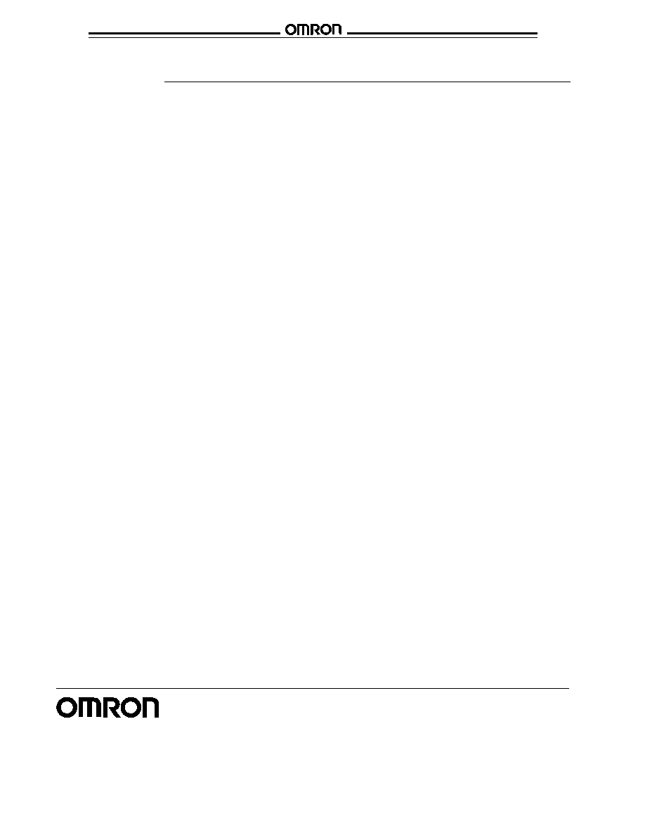
Unit: mm (inch)
s
ACCESSORIES
Mounting Bracket A
Mounting Bracket B
4.2 dia.
13
(0.51)
4.2
(0.17)
19
(0.75)
24 (0.94)
35 (1.38)
25 (0.98)
1.8
(0.07)
Two-3.7 dia.
30 (1.18)
22
(0.87)
22
(0.87)
26 (1.02)
Provided with E8Y
4.2 dia.
16.4 (0.65)
35 (1.38)
25 (0.98)
Two-3.7 dia.
1.8
(0.07)
Provided with E8Y
4.2
(0.17)
13 (0.51)
19.6 (0.77)
15 (0.59)
15.6
(0.61)
11.4
(0.45)
30 (1.18)
22
(0.87)
s
CONTROLLER OF FLOW SENSOR
Vertical-mounting Type
E8Y-A5C-F03V
E8Y-A5C-F20V
Horizontal-mounting Type
E8Y-A5C-F03H
E8Y-A5C-F20H
IN
OUT
31 (1.22)
13 dia.
67.3
(2.65)
47.3
(1.86)
30
(1.18)
Two-Rc (PT)
1/8 taper screw
41.3 (1.63)
14 (0.55)
Vinal-insulated round
cable 4.0 dia. 4 cores
5 (0.20)
2 m (78.7)
30 (1.18)
10 (0.39)
20 (0.79)
23 (0.91)
39.3
(1.55)
Mounting holes
(through) Two-3.7 dia.
Mounting screw
(through) Two-M3 screw
IN
OUT
31
(1.22)
13 dia.
67.3 (2.65)
47.3 (1.86)
30 (1.18)
41.3 (1.63)
14 (0.55)
7 (0.28)
Two-Rc (PT)
1/8 taper screw
5 (0.20)
2 m (78.7)
30 (1.18)
10 (0.39)
20 (0.79)
Vinal-insulated round
cable 4.0 dia. 4 cores
33.5 (1.32)
23 (0.91)
39.3 (1.55)
Mounting holes
(through)
Two-3.7 dia.
Mounting screw
(through)
Two-M3 screw
Two-1/8 NPT
taper screw
Two-1/8 NPT
taper screw
Two-3.7 (0.15) dia.
Two-3.7 (0.15) dia.
Vinyl-insulated round
cable 4.0 dia. 4 cores
Vinyl-insulated round
cable 4.0 dia. 4 cores

E8Y
E8Y
9
s
PANEL MOUNTING BRACKET
E89-Y1 Panel Mounting Bracket (sold separately)
Panel Cutout Dimensions
Note: Approximate panel thickness
is 1.0 to 3.5 mm.
70
(2.76)
70
(2.76)
40
(1.57)
48
(1.89)
36
+0.5
(1.42
+0.02
)
0
0
45
+0.5
(1.77
+0.02
)
0
0
36
+0.5
(1.42
+0.02
)
0
0
45
+0.5
(1.77
+0.02
)
0
0
40 (1.57)
41.6
(1.64)
38.8 (1.53)
39.8 (1.57)
30.9 (1.22)
40
(1.57)
10.8
(0.43)
57
(2.24)
15 (0.59)
6
(0.24)
4
(0.16)
48 (1.89)
48
(1.89)
36.8 (1.45)
28.9 (1.14)
8.8
(0.35)
57
(2.24)
15 (0.59)
8
(0.31)
6
(0.24)
With Mounting 36 Panel
With Mounting 45 Panel
Cover
Guide
Frame
Holder
36 x 36 Panel
45 x 45 Panel (DIN size)
Cover
Guide
Holder
(Panel)
Cover
Guide
Frame
Holder
(Panel)
E8Y
E8Y
Precautions
s
ENVIRONMENT
∑ Do not use this product where explosive gas, ignitable gas,
or any other harmful gas may be present.
∑ Do not use beyond rated supply voltage or under AC power
supply. Explosion or fire may be caused.
∑ Do not mix up DC pole's wiring. Explosion or fire may be
caused.
∑ This product cannot be used under corrosive gas or
flammable gas.
∑ Do not install beside high voltage line or power line.
∑ Do not expose to water.
∑ Do not effect the product by ultrasonic vibration.
s
CORRECT USE
∑ Use within rated pressure.
∑ Do not mix up connecting +, ≠ sign of pressure port. The "+"
sign is for plus pressure, the "≠" sign for minus pressure.
∑ Do not pull the cable more than 50 N (11.25 lbs).
∑ Filter the gas with an appropriate air filter so that the applied
gas will be free of moisture or oil.
∑ When not using linear output and/or the ON/OFF output, cut
the output lead wire and cover the tip with an insulation tube
to prevent wrong connection.
OMRON ELECTRONICS LLC
OMRON CANADA, INC.
One East Commerce Drive
885 Milner Avenue
Schaumburg, IL 60173
Scarborough, Ontario M1B 5V8
1-800-55-OMRON
416-286-6465
Cat. No. CEDSAX4
11/01
Specifications subject to change without notice.
Printed in the U.S.A.
OMRON ON-LINE
Global - http://www.omron.com
USA - http://www.omron.com/oei
Canada - http://www.omron.com/oci