
Internal Circuit
Terminal No.
Name
A
Anode
K
Cathode
C
Collector
E
Emitter
Dimensions
Tolerance
3 mm max.
±0.3
3 < mm 6
±0.375
6 < mm 10
±0.45
10 < mm 18
±0.55
18 < mm 30
±0.65
Unless otherwise specified, the
tolerances are as shown below.
A
K
C
E
Optical axis
Optical axis
Two, 3.2 dia. holes
Four, 0.5
Four, 0.25
EE-SB5
EE-SB5-B
11.5±0.2
9±0.2
7.62±0.3
2.54±0.2
2.54±0.2
204
Photomicrosensor
(Reflective)
EE-SB5(-B)
Dimensions
Note: All units are in millimeters unless otherwise indicated.
Features
∑
Dust-tight construction model with a 5 mm sensing distance.
∑
With a visible-light intercepting filter which allows objects
to be sensed without being greatly influenced by the light
radiated from fluorescent lamps.
∑
Mounted with M3 screws.
Absolute Maximum Ratings
(Ta = 25∞C)
Item
Symbol
Rated
value
Emitter
Forward current
I
F
50 mA
(see note 1)
Pulse forward
current
I
FP
1 A
(see note 2)
Reverse voltage
V
R
4 V
Detector
Collector--Emitter
voltage
V
CEO
30 V
Emitter--Collector
voltage
V
ECO
---
Collector current I
C
20 mA
Collector
dissipation
P
C
100 mW
(see note 1)
Ambient
temperature
Operating
Topr
--25∞C to
80∞C
Storage
Tstg
--30∞C to
80∞C
Soldering temperature
Tsol
260∞C
(see note 3)
Note: 1. Refer to the temperature rating chart if the ambient
temperature exceeds 25∞C.
2. The pulse width is 10 µs maximum with a frequency
of 100 Hz.
3. Complete soldering within 10 seconds.
Ordering Information
Description
Part number
Photomicrosensor (Reflective) with soldering terminals
EE-SB5
Photomicrosensor (Reflective) with PCB terminals
EE-SB5-B
Electrical and Optical Characteristics (Ta = 25∞C)
Item
Symbol
Value
Condition
Emitter
Forward voltage
V
F
1.2 V typ., 1.5 V max.
I
F
= 30 mA
Reverse current
I
R
0.01 µA typ., 10 µA max.
V
R
= 4 V
Peak emission wavelength
P
940 nm typ.
I
F
= 20 mA
Detector
Light current
I
L
200 µA min., 2,000 µA max.
I
F
= 20 mA, V
CE
= 10 V
White paper with a reflection ratio of 90%,
d = 5 mm (see note)
Dark current
I
D
2 nA typ., 200 nA max.
V
CE
= 10 V, 0 x
Leakage current
I
LEAK
2 µA max.
I
F
= 20 mA, V
CE
= 10 V with no reflection
Collector--Emitter
saturated voltage
V
CE
(sat)
---
---
Peak spectral sensitivity
wavelength
P
850 nm typ.
V
CE
= 10 V
Rising time
tr
30 µs typ.
V
CC
= 5 V, R
L
= 1 k, I
L
= 1 mA
Falling time
tf
30 µs typ.
V
CC
= 5 V, R
L
= 1 k, I
L
= 1 mA
Note: The letter "d" indicates the distance between the top surface of the sensor and the sensing object.
EE-SB5(-B)
EE-SB5(-B)
205
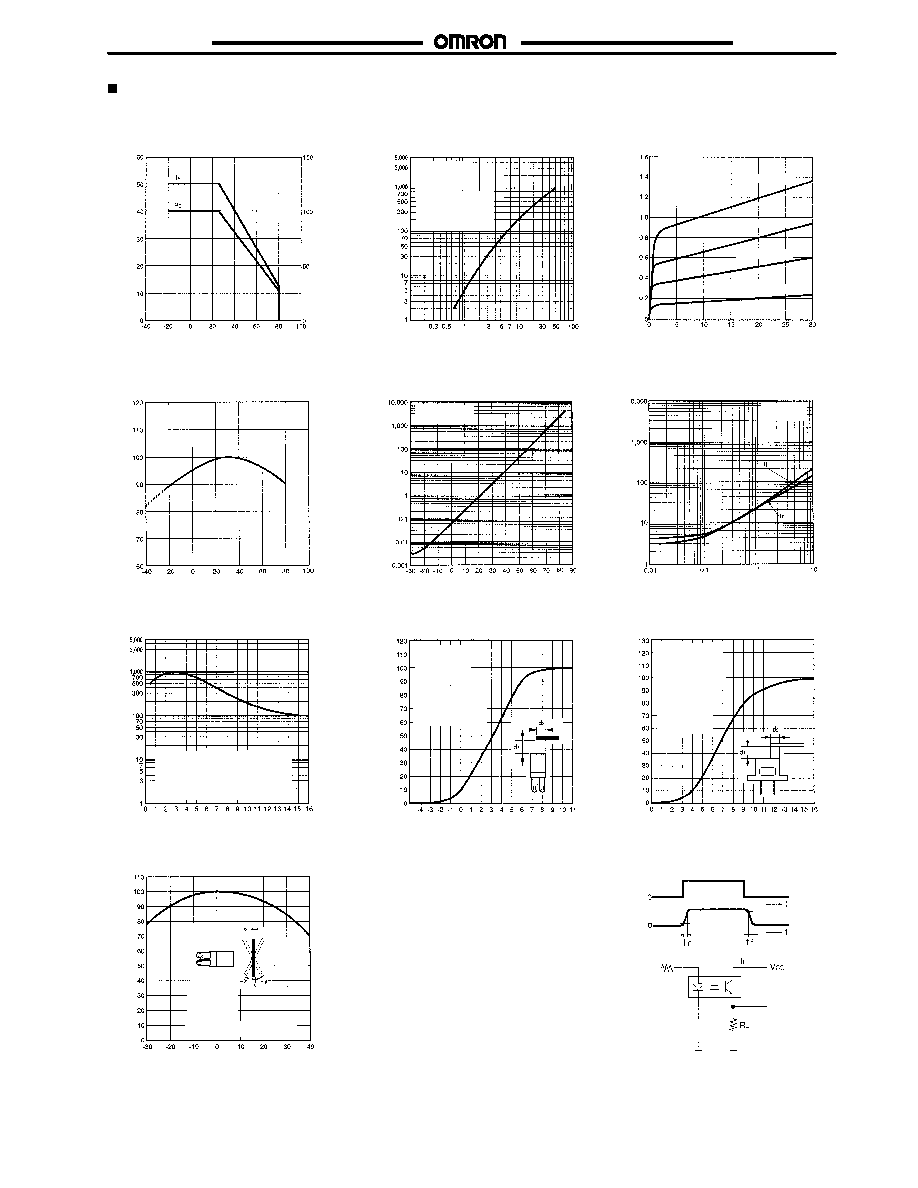
Engineering Data
Forward Current vs. Collector
Dissipation Temperature Rating
Light Current vs. Forward Current
Characteristics (Typical)
Ambient temperature Ta (∞C)
Collector
dissipation
P
c
(
mW)
F
Forward
c
urrent
I
(
mA)
Forward current I
F
(mA)
Light
current
I
(
mA)
L
Light Current vs. Collector--Emitter
Voltage Characteristics (Typical)
Relative Light Current vs.
Ambient Temperature
Characteristics (Typical)
Dark Current vs. Ambient
Temperature Characteristics
(Typical)
Collector--Emitter voltage V
CE
(V)
Light
current
I
(
mA)
L
Ambient temperature Ta (∞C)
Ambient temperature Ta (∞C)
Response Time vs. Load
Resistance Characteristics
(Typical)
Sensing Distance Characteristics
(Typical)
Response Time Measurement
Circuit
Load resistance R
L
(k)
Distance d
2
(mm)
Sensing Angle Characteristics
(Typical)
Angle deviation (∞)
I
F
= 20 mA
V
CE
= 5 V
V
CE
= 10 V
0 x
Vcc = 5 V
Ta = 25∞C
Input
Output
Input
Output
90 %
10 %
Distance d (mm)
Sensing Position Characteristics
(Typical)
Relative
light
current
I
(
%)
L
Dark
current
I
(
nA)
D
Response
t
ime
t
r
,
tf
(
s
)
µ
Relative
light
current
I
(
%)
L
Relative
light
current
I
(
%)
L
Sensing object:
White paper with
a reflection fac-
tor of 90%
Sensing object:
White paper with
a reflection factor
of 90%
I
F
= 20 mA
I
F
= 10 mA
I
F
= 30 mA
I
F
= 40 mA
Ta = 25∞C
V
CE
= 10 V
d = 5 mm
Ta = 25∞C
d = 5 mm
Ta = 25∞C
I
F
= 20 mA
V
CE
= 10 V
Sensing object: White paper
with a reflection factor of 90%
Sensing object:
White paper
with a reflection
factor of 90%
Sensing ob-
ject: White
paper with a
reflection fac-
tor of 90%
Sensing object: White paper
with a reflection factor of 90%
I
F
= 20 mA
V
CE
= 10 V
Ta = 25∞C
d
1
= 5 mm
I
F
= 20 mA
V
CE
= 10 V
Ta = 25∞C
d
1
= 5 mm
Ta = 25∞C
I
F
= 20 mA
V
CE
= 10 V
d = 5 mm
Distance d
2
(mm)
Sensing Position Characteristics
(Typical)
Relative
light
current
I
(
%)
L
µ
Light
current
I
L
(A
)

Cat. No. NAPMS≠1
02/03 Specifications subject to change without notice. Printed in U.S.A.
OMRON ELECTRONICS LLC
One East Commerce Drive
Schaumburg, IL 60173
NOTE: DIMENSIONS SHOWN ARE IN MILLIMETERS. To convert millimeters to inches divide by 25.4.
847≠882≠2288
OMRON CANADA, INC.
885 Milner Avenue
416-286-6465
R
OMRON ON≠LINE
Global ≠ http://www.omron.com
USA ≠ http://www.omron.com/oei
Canada ≠ http://www.omron.com/oci
Toronto, Ontario M1B 5V8