Document Outline
- Front Page
- Ordering Information
- Specifications
- Enginerring Data
- Operation
- Dimensions
- Precautions
- Contacting Omron
EE-SB5M/SB5MC/SB5V/SB5VC/SB5V-E
Photomicrosensor with 80-mA
Switching Capacity that can be Built
into Equipment
Built-in amplifier
Models available with 5- to 12-VDC and
5- to 15-VDC input
CMOS- and TTL-compatible
Model with easy adjustment with an
external sensitivity adjuster (EE-SB5V)
Special connectors (EE-1001/1006) are
available
19-mm sensing distance (EE-SB5V-E)
Convert to PNP output with EE-2002
conversion connector
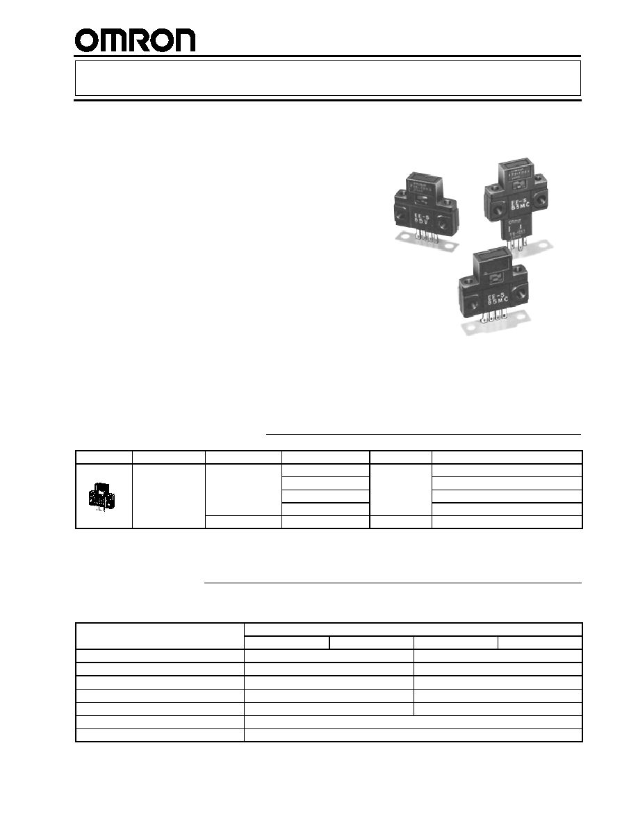
Ordering Information
Appearance
Sensing method
Sensing distance
Output configuration
Weight
Part number
Reflective
5 mm
Light-ON
Approx. 3.0 g
EE-SB5M
Dark-ON
g
EE-SB5MC
Light-ON
EE-SB5V
Dark-ON
EE-SB5VC
19 mm
Light-ON
Approx. 2.8 g
EE-SB5V-E
Specifications
RATINGS
Item
Reflective
EE-SB5M
EE-SB5MC
EE-SB5V(-E)
EE-SB5VC
Supply voltage
5 to 12 VDC
�
10%, ripple (p-p): 10% max.
5 to 15 VDC
�
10%, ripple (p-p): 10% max.
Current consumption
36 mA max.
48 mA max. (DC current: I
F
= 25 mA)
Maximum forward direct current (I
F
)
--
30 mA max.
Forward voltage (V
F
)
--
1.5 V max. (I
F
= 30 mA)
Reverse voltage (V
R
)
--
4 V max.
Standard reference object
White paper with reflection factor of 90% (standard sensing object: 15 x 15 mm)
Differential distance
0.1 mm
(This table continues on the next page.)

EE-SB5M/SB5MC/SB5V/SB5VC/SB5V-E
EE-SB5M/SB5MC/SB5V/SB5VC/SB5V-E
Specifications Table
-- continued from previous page
Item
Reflective
EE-SB5M
EE-SB5MC
EE-SB5V(-E)
EE-SB5VC
Control output
At 5 to 24 VDC: 80-mA load current (I
C
) with a residual voltage of 0.8 V max.
When driving TTL: 40-mA load current (I
C
) with a residual voltage of 0.4 V max.
Output
configuration
Transistor on output stage
without detecting object
OFF
ON
OFF
ON
Transistor on output stage
with detecting object
ON
OFF
ON
OFF
Response frequency*
50 Hz
Connecting method
EE-1001/1006 Connectors; soldering terminals
Light source
GaAs infrared LED with a peak wavelength of 940 nm
Receiver
Si photo-transistor with a sensing wavelength of 850 nm max.
*The response frequency was measured by detecting the following disks rotating.
Disk
15 mm
15 mm
15 mm
5 mm
200 mm
dia.
CHARACTERISTICS
Ambient temperature
Operating
-25
�
C to 55
�
C (-13
�
F to 131
�
F)
Storage
-30
�
C to 80
�
C (-22
�
F to 176
�
F)
Ambient humidity
Operating
45% to 85%
y
Storage
35% to 95%
Vibration resistance
Destruction: 20 to 2,000 Hz (with a peak acceleration of 20G's), 1.5-mm double amplitude for
4 min each in X, Y, and Z directions
Shock resistance
Destruction: 500 m/s
2
for 3 times each in X, Y, and Z directions
Soldering heat resistance
260
��
5
�
C (See Note.) when the portion between the tip of the terminals and the position
1.5 mm from the terminal base is dipped into the solder for 10
�
1 seconds
Note: This conforms to MIL-STD-750-2031-1.

EE-SB5M/SB5MC/SB5V/SB5VC/SB5V-E
EE-SB5M/SB5MC/SB5V/SB5VC/SB5V-E
Engineering Data
OPERATING RANGE (TYPICAL 1)
OPERATING RANGE (TYPICAL 2)
Di
s
t
anc
e
Y
(m
m
)
X (mm)
EE-SB5M(C)
Reference object:
White paper ( 15 x 15 mm)
(reflection factor: 90%)
Operates
Releases
Optical
axis
X
Y
Di
s
t
anc
e
Y
(m
m
)
X' (mm)
EE-SB5M(C)
Reference ob-
ject: White paper
(15 x 15 mm)
(reflection factor:
90%)
Operates
Releases
Optical
axis
X'
Y
SENSING DISTANCE VS. OBJECT
AREA (TYPICAL)
SENSING DISTANCE VS. I
F
EE-SB5V-E
(TYPICAL)
Di
s
t
anc
e
(
m
m
)
EE-SB5M(C)
Reference object:
White paper ( 15 x 15 mm)
(reflection factor: 90%)
Area (mm
2
)
0
5
10
15
20
25
30
4
8
12
16
20
Forward Current I
F
(mA)
S
ens
i
n
g
D
i
s
t
anc
e
d
(
m
m
)
T
A
= 25
�
C
Reference object
White paper:
(reflection factor 90%)
EE-SB5M/SB5MC/SB5V/SB5VC/SB5V-E
EE-SB5M/SB5MC/SB5V/SB5VC/SB5V-E
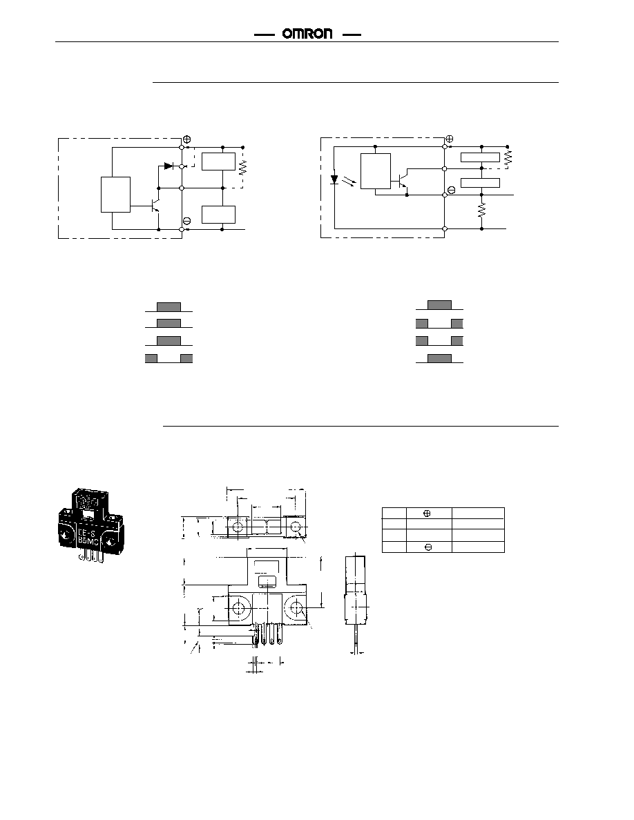
Operation
INTERNAL/EXTERNAL CIRCUIT DIAGRAMS
EE-SB5M(C) Light-ON/Dark-ON
EE-SB5V(C), EE-SB5V-E Light-ON/Dark-ON
Load
(relay)
Main
circuit
Logic
circuit
OUT
5 to 12 VDC
L
0 V
I
C
R
L
Connect R
L
as
shown only
when logic cir-
cuit is driven.
LED
display
Load (relay)
Main
circuit
Logic circuit
OUT
5 to 15 VDC
R
L
0 V
L
I
C
R
F
Current-limiting
resistor
TIMING CHART
ON
OFF
Output
transistor
Operates
Releases
Load (relay)
H
L
Output voltage
(logic)
ON
OFF
Output
transistor
Operates
Releases
Load (relay)
H
L
Output voltage
(logic)
Interrupted
Incident
Interrupted
Incident
Light-ON
Dark-ON
Dimensions
Unit: mm (inch)
EE-SB5M(C), EE-SB5V(C), EE-SB5V-E
Optical axis
Two, 3.2 dia.
holes
Optical
axis
Two, 3.8 dia.
holes
(1)(2)(3)(4)
Terminal Arrangement
(1)
(2)
(3)
(4)
V
CC
OUT
L
OUTPUT
GND (0 V)
L
25.4 (1.00)
19.0 (0.75)
9.8
(0.39)
6.95
(0.27)
6.35
(0.25) 4.55
(0.18)
9.0
(0.35)
13.2
(0.52)
5.5
(0.22)
8.0
(0.31)
6.2
(0.24)
2.55
(0.10)
0.6
(0.02)
1.2 (0.05)
1.5
13.0 (0.51)
0.8
(0.03)
1.45 (0.06)
2.54 (0.10)
0.3
(0.01)
16.7
(0.66)

EE-SB5M/SB5MC/SB5V/SB5VC/SB5V-E
EE-SB5M/SB5MC/SB5V/SB5VC/SB5V-E
10.8
(0.48)
6.0
(0.24)
22.2
(0.87)
26
(1.02)
16.2
(0.64)
EE-SB5M(C)/SB5V(C)/SB5V-E + EE-1001
EE-SB5M(C)/SB5V(C)/SB5V + EE-1006
EE-1001 CONNECTOR
2.54
�
0.15
2.9
�
1
4.0
(0.16)
10.8
(0.43)
6.0
(0.24)
0.6
(0.02)
13.0 (0.51)
EE-1006 CONNECTOR WITH CABLE
(1)
(2)
(3)
(4)
Terminal Arrangement
IEC colors are shown in parentheses.
(1)
Red (Brown)
V
CC
(2)
Yellow (Pink)
L
L
(3)
White (Black)
OUT
OUTPUT
(4)
Black (Blue)
GND (0 V)
0.6
(0.02)
11.8
(0.46)
2.54
(0.10)
5.3
(0.21)
16.2 (0.64)
20 (0.79)
2,000
(78.74)
25
(0.98)
15
(0.59)
Note: Supply 5 to 12 V to the EE-SB5M(C). Wire as shown by the following diagram if the supply voltage exceeds 12 V.
V
CC
(1)
V
CC
(2)
R
GND
Z
V
CC
(2) = V
CC
(1) x
Z
Z + R
Note: Z is the internal impedance between the positive and negative terminals.
Model
V
CC
(2)
Z (
)
EE-SB5M(C)
5 to 12 V
360