Document Outline
- First page
- Ordering information
- Specifications
- Engineering data
- Operation
- Dimensions
- Precautions
- Contact Omron
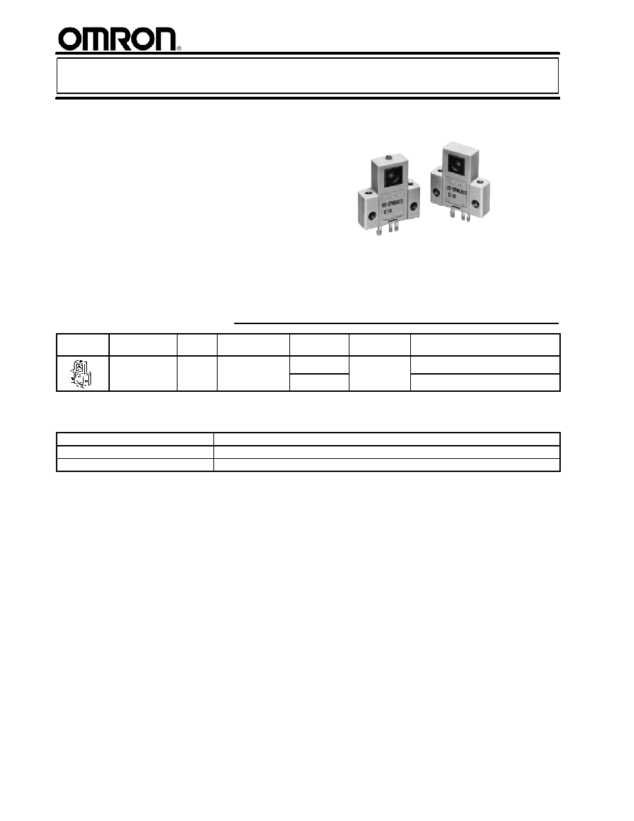
EE-SPW311/411
Photomicrosensor with a Sensing
Distance as Long as 1 m
H
Easy-to-see Light-ON indicator
H
Wide operating voltage range: 5 to
24 VDC
H
Light modulation effectively reduces
external light interference
H
Easy-to-wire connector ensures ease of
maintenance
H
Convert to PNP output with EE-2002
conversion connector
Ordering Information
Appearance Sensing method Sensing
distance
Sensing object
Output
configuration
Weight
Part number
Through beam
1 m
Opaque material,
5 mm dia min
Dark-ON
Approximately
8.8 g
EE-SPW311
5 mm dia. min.
Light-ON
8.8 g
EE-SPW411
Note: Wire Harness/Connector included with EE-SPW311 and EE-SPW411
J
ACCESSORIES
Name
Part number
Connector for Emmitter
EE-1006L
Connector for Receiver
EE-1006D

EE--SPW311/411
EE--SPW311/411
2
Specifications
J
RATINGS
Item
Transmissive type
EE-SPW311
EE-SPW411
Supply voltage
5 (-5%) to 24 (+10%) VDC, ripple (p-p): 10% max.
Current consumption
40 mA max. (emitter: 20 mA max.; receiver: 20 mA max.)
Sensing distance
1 m
Standard reference object
Opaque: 5 mm dia. min.
Directional angle
5� to 20�
Control output
At 5 to 24 VDC: 100 mA load current (I
C
) with a residual voltage of 0.8 V max.
When driving TTL: 40 mA load current (I
C
) with a residual voltage of 0.4 V max.
Output
configuration
Transistor on output stage
without detecting object
OFF
ON
Transistor on output stage
with detecting object
ON
OFF
Indicator
(S
N t )
Without detecting object
ON
(See Note.)
With detecting object
OFF
Response frequency
100 Hz max. (200 Hz typ.)
Connecting method
Dedicated connectors: EE-1006L and EE-1006D
Light source
GaAs infrared LED (pulse modulated) with a peak wavelength of 940 nm
Receiver
Si photo-transistor with a sensing wavelength of 850 nm max.
Note: The indicator is a GaP red LED (peak emission wavelength: 700 nm).
J
CHARACTERISTICS
Ambient illumination*
Sensing face: fluorescent light: 1,000 x max.; incandescent light: 3,000 x max.
Enclosure ratings
IP60
Ambient temperature
Operating
-10�C to 55�C (14�F to 131�F)
p
Storage
-25�C to 80�C (-13�F to 176�F)
Ambient humidity
Operating
45% to 85%
y
Storage
35% to 95%
Vibration resistance
Destruction: 200 to 2,000 Hz (with a peak acceleration of 10G's), 1.5-mm double
amplitude for 2 hrs (with 4-minute cycles) each in X, Y, and Z directions
Shock resistance
Destruction: 500 m/s
2
(approx. 50G) for 3 times each in X, Y, and Z directions
Material
Case: PBT; lens: polycarbonate
Cable length
10 m max. with a cross-sectional area of 0.3 mm
2
min. (AWG24 min.)
Note: *The ambient illumination is measured on the surface of the receiver.

EE--SPW311/411
EE--SPW311/411
3
Engineering Data
J
RECEIVER OUTPUT VS. SENSING
DISTANCE (TYPICAL)
J
PARALLEL MOVEMENT
CHARACTERISTICS (TYPICAL)
Excess
gain
Operating voltage
Distance between sensors (cm)
Distance
Y
(mm)
Distance X (cm)
Y
X
Operation
J
INTERNAL/EXTERNAL CIRCUIT DIAGRAM
Light-ON/Dark-ON
Operation
indicator
Load
(relay)
Logic
circuit
OUT
5 to 24 VDC
I
C
0 V
Main
circuit
R
L
Connect R
L
only
when a logic cir-
cuit is driven.
J
TIMING CHART
Light-ON
ON
OFF
LIGHT indicator
(red)
ON
OFF
Output
transistor
Operates
Releases
Load (relay)
H
L
Output voltage
(logic)
Interrupted
Incident
Dark-ON
ON
OFF
LIGHT indicator
(red)
ON
OFF
Output
transistor
Operates
Releases
Load (relay)
H
L
Output voltage
(logic)
Interrupted
Incident

EE--SPW311/411
EE--SPW311/411
4
Dimensions
Unit: mm (inch)
J
EE-SPW311/SPW411
Emitter
Sensing
window
Two, 3.8 dia.
holes
Sensing
window
Two, 3.2 dia. holes
Two, 3.8 dia.
holes
Two, 3.2 dia. holes
Indicator
(1) (2)
(3)
(1) (2)
(3)
Receiver
Terminal Arrangement
(1)
(2)
(3)
V
CC
OUT
GND (0 V)
(1)
(2)
(3)
V
CC
OUT
OUTPUT
GND (0 V)
Emitter (EE-SPWL_11)
Receiver (EE-SPWD_11)
25.4 (1.00)
19 (0.75)
0.6
(0.02)
8 (0.31)
19 (0.75)
13.4 (0.53)
27
(1.06)
15.1
(0.59)
14.1
(0.56)
6.2 (0.24)
5.5
(0.22)
2.54 (0.10)
7.4
(0.29)
0.7
(0.03)
0.3
(0.01)
25.4 (1.00)
19 (0.75)
8 (0.31)
0.6
(0.02)
19 (0.75)
13.4 (0.53)
27
(1.06)
15.1
(0.59)
14.1
(0.56)
5.5
(0.22)
6.2 (0.24)
2.54 (0.10)
1.5
(0.06)
7.4
(0.29)
0.7
(0.03)
0.3
(0.01)
J
EE-1006L CONNECTOR FOR EMITTER (ATTACHMENT)
(1) Brown (Red) V
CC
(4) Blue (Black)
GND (0 V)
(1)
(2)
(3)
(4)
Terminal Arrangement
Note: Older standard colors are shown in
parentheses. The connector comes
with an 18 strand, 0.12-wire, 2-m
attached RED CABLE.
11.8
(0.46)
5.3
(0.21)
2.54 (0.10)
16.2 (0.64)
0.6 (0.02)
20 (0.79)
2,000 (78.74)
J
EE-1006D CONNECTOR FOR RECEIVER (ATTACHMENT)
(1)
(2)
(3)
(4)
Terminal Arrangement
(1) Brown
(Red)
(2) Black
(White)
OUTPUT
(3) Blue
(Black)
GND (O V)
V
CC
Note: Older standard colors are shown in
parentheses. The connector comes
with an 18 strand, 0.12-wire, 2-m
attached GRAY CABLE.
11.8
(0.46)
16.2 (0.64)
0.6 (0.02)
20 (0.79)
2,000 (78.74)
5.3
(0.21)
2.54
(0.10)

EE--SPW311/411
EE--SPW311/411
Precautions
Refer to the Technical Information Section for general
precautions.
J
CHEMICAL RESISTANCE
The sensing window is made of a polycarbonate resin which
withstands chloride solvents and strong acids but is soluble in
strong alkali, aromatic hydrocarbons, and aliphatic
hydrocarbonate chloride solvents.
J
AXIS ADJUSTMENT
1. When mounting the emitter and receiver, ensure that the
center line of each lens will be on the same plane (refer to
the diagrams).
Side view
Top view
2. Turn on the emitter and receiver after making sure that they
have been wired correctly. When power is turned on, the
operation indicator on the receiver will light. Make sure the
operation indicator is off when an object intercepts the optical
axis and the operation indicator lights again when the object
is removed.
3. Fix the position of the receiver (or emitter) securely, move the
emitter (or receiver) horizontally and vertically to check the
range in which the operation indicator is lit. Then locate the
emitter (or receiver) in the center of the range, and fix the
position securely.
J
CONNECTION
Extra care must be taken when making connections to the units
because they are protected against reverse polarity.
Install the wiring for the photomicrosensor in a separate wiring
duct well away from both supply lines and high voltage cables to
prevent damage or faulty operation from induced transients.
Any extension must be shorter than 10 meters with wire that has
a cross-sectional area greater than 0.3 mm
2
.
J
POWER SUPPLY
When using a commercial switching regulator, the frame ground
(FG) and ground (G) pins must be grounded. Failure to do so
may result in faulty operation due to switching noise.
J
LOADS
Operate the sensor with a load. The sensor is not protected
against short circuits.
When the photomicrosensor is turned on, a period of
approximately 1 to 3 ms is required for the photomicrosensor to
operate stably.
Cat. No. GC APMS-1 09/02 Specifications subj ect to c hange without notice. Printed i n U.S.A.
OMRON ELECTRONICS LLC
One East Commerce Drive
Schaumburg, IL 60173
NOTE: DIMENSIONS SHOWN ARE IN MILLIMETERS. To convert millimeters to inches divide by 25.4.
1-800-55-OMRON
OMRON CANADA, INC.
885 Milner Avenue
416-286-6465
R
OMRON ON--LINE
Global -- http://www.omron.com
USA -- http://www.omron.com/oei
Canada -- http://www.omron.com/oci
Toronto, Ontario M1B 5V8