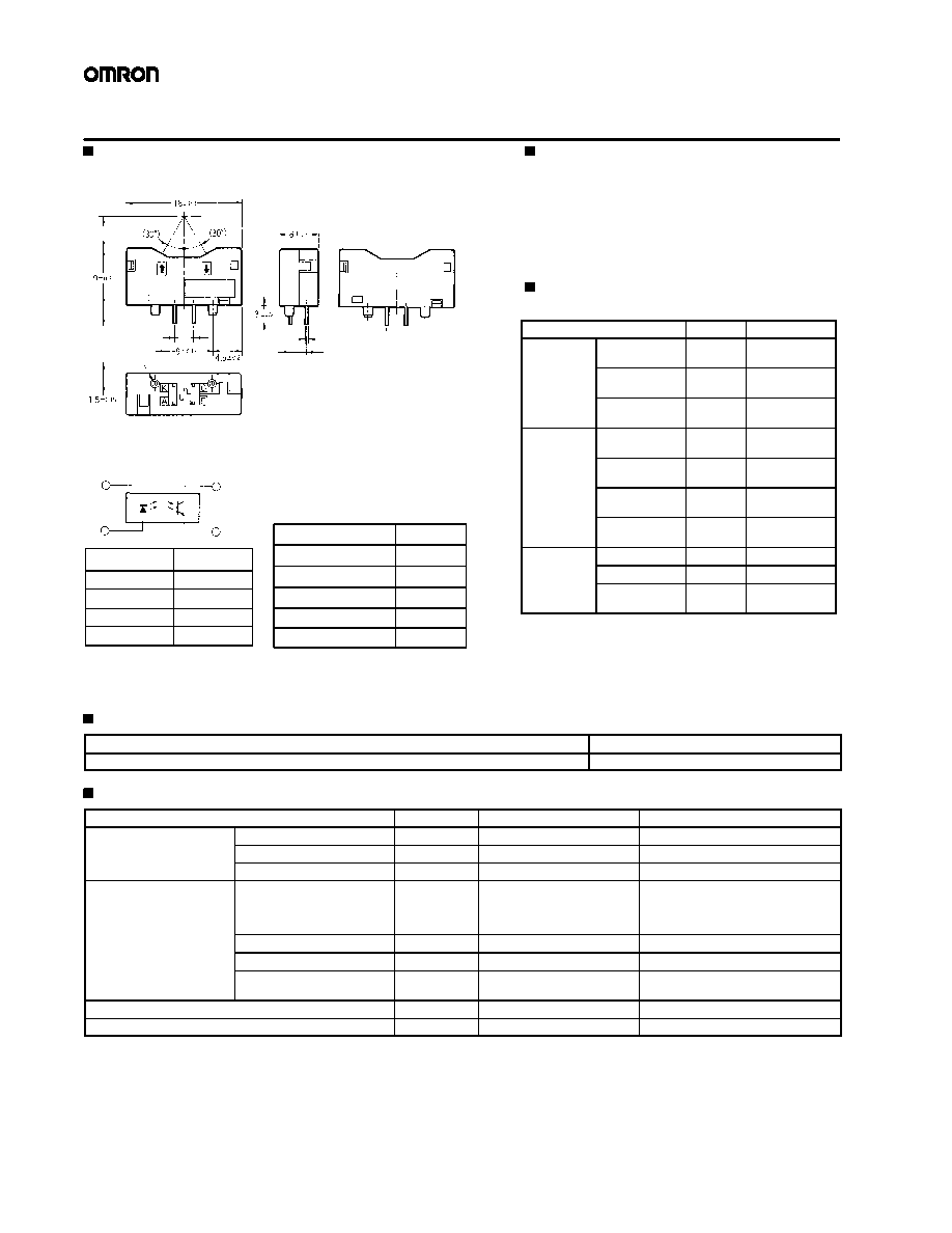
Terminal No.
Name
A
Anode
K
Cathode
C
Collector
E
Emitter
Dimensions
Tolerance
3 mm max.
±0.3
3 < mm ± 6
±0.375
6 < mm ± 10
±0.45
10 < mm ± 18
±0.55
18 < mm ± 30
±0.65
Internal Circuit
Two, 1.3 dia.
K
A
C
E
Four, 0.4 × 0.4
5
3
1.6
2.54
Unless otherwise specified, the
tolerances are as shown below.
26
Micro-displacement Sensor
EE-SY190
Dimensions
Note: All units are in millimeters unless otherwise indicated.
Features
·
High-precision optical technology ensures excellent
limited sensing range and sensing position
characteristics.
·
Ideal for paper/OHP detection in OA/CP markets.
·
Compact package (length 18mm x width 6mm x
height 9 mm).
Absolute Maximum Ratings
(Ta = 25°C)
Item
Symbol
Rated value
Emitter
Forward current
I
F
50 mA
(See Note 1.)
Pulse forward
current
I
FP
1 A
(See Note 2.)
Reverse
voltage
V
R
4 V
Receiver
Collector-emitter
voltage
V
CEO
30 V
Emitter-collector
voltage
V
ECO
---
Collector
current
I
C
20 mA
Collector
dissipation
P
C
100 mW
(See Note 1.)
Ambient
t
t
Operating
Topr
-25°C to 85°C
b e
temperature Storage
Tstg
-40°C to 100°C
Soldering
Tsol
260°C
(10 secs max.)
Note: 1. Refer to the Temperature Characteristics
curves contained within the Engineering Data
section if temperature exceeds
25°C
.
2. The pulse width is 10 µs maximum with a fre-
quency of 100 Hz.
Ordering Information
Description
Part number
Micro-displacement sensor
EE-SY190
Electrical and Optical Characteristics (Ta = 25°C)
Item
Symbol
Value
Condition
Emitter
Forward voltage
V
F
1.2 V typ., 1.5 V max.
I
F
= 30 mA
e
Reverse current
I
R
10 µA max.
V
R
= 4 V
Peak emission wavelength
P(L)
940 nm typ.
I
F
= 30 mA
Receiver
Light current (See Note)
I
L
50 µA min., 180 µA typ.,
600 µA max.
I
F
= 20 mA, V
CE
= 5 V
White paper with a reflection factor of
90%, d = 4.5 mm
(See Note 1.)
Dark current
I
D
2 nA typ., 100 nA max.
V
CE
= 5 V, 0 x
Leakage current
I
LEAK
1 µA max.
I
F
= 20 mA, V
CE
= 5 V without object
Peak spectral sensitivity
wavelength
P(P)
850 nm typ.
V
CE
=5 V
Rising time
tr
30 µs typ.
V
CC
= 5 V, R
L
= 1 k, I
L
= 200 µA
Falling time
tf
30 µs typ.
V
CC
= 5 V, R
L
= 1 k, I
L
= 200 µA
Note: The letter "d" indicates the distance between the top surface of the sensor and the sensing object.
EE-SY190
EE-SY190
27
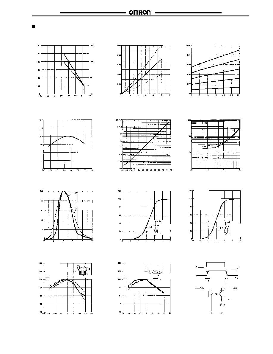
Engineering Data
Forward Current vs. Collector
Dissipation Temperature Rating
Light Current vs. Forward Current
Characteristics (Typical)
Ambient temperature Ta (°C)
Collector
dissipation
Pc
(mW)
F
Forward
c
urrent
I
(mA)
Forward current I
F
(mA)
Light Current vs. Collector--Emitter
Voltage Characteristics (Typical)
Relative Light Current vs.
Ambient Temperature
Characteristics (Typical)
Dark Current vs. Ambient
Temperature Characteristics
(Typical)
Collector--Emitter voltage V
CE
(V)
Ambient temperature Ta (°C)
Ambient temperature Ta (°C)
Response Time vs. Load
Resistance Characteristics
(Typical)
Sensing Distance Characteristics
(Typical)
Response Time Measurement
Circuit
Load resistance R
L
(k)
Distance d
2
(mm)
Sensing Angle Characteristics
(Typical)
Angle deviation (°)
I
F
= 20 mA
V
CE
= 5 V
Input
Output
Input
Output
90 %
10 %
Distance d (mm)
Sensing Position Characteristics
X Direction (Typical)
Relative
light
current
I
(
%)
L
Dark
current
I
(
nA)
D
Response
t
ime
t
r
,
tf
(
s
)
µ
Relative
light
current
I
(
%)
L
Relative
light
current
I
(
%)
L
Distance d
2
(mm)
Sensing Position Characteristics
Y Direction (Typical)
Relative
light
current
I
(
%)
L
Sensing Angle Characteristics
(Typical)
Angle deviation (°)
Relative
light
current
I
(
%)
L
V
CE
= 10 V
0 x
R
e
l
a
t
i
v
e
l
i
g
h
t
c
u
r
r
e
n
t
I
(
%
)
L
Light
current
I
(
A)
L
µ
Light
current
I
(
A)
L
µ
I
F
P
C
Ta = 25°C
d = 4.5 mm
Sensing object:
White paper with
a reflection factor
of 90%
I
F
= 50 mA
I
F
= 40 mA
I
F
=30 mA
I
F
= 20 mA
I
F
=10 mA
I
F
= 20 mA
V
CE
= 5 V
Sensing object: White
paper with a reflection
factor of 90%
d
1
= 4.5 mm
Direction (X)
Sensor
Direction (Y)
Sensor
I
F
= 20 mA
V
CE
= 5 V
Sensing object:
White paper with a
reflection factor of
90%
d
1
= 4.5 mm
Side with im-
pressed model no
Ta = 25°C
I
F
= 20 mA
V
CE
= 5 V
White paper with a
reflection factor of 90%
d = 4.0 mm
d = 4.5 mm
d = 5.0 mm
Sensor
Sensor
White paper with a
reflection factor of
90%
d = 4.0 mm
d = 4.5 mm
d = 5.0 mm
Side with impressed
model no
Ta = 25°C
I
F
= 20 mA
V
CE
= 5 V
Sensing
object: White
paper with a
reflection
factor of 90%
d = 4.5 mm
V
CE
= 5 V
V
CE
= 5 V
Ta = 25°C
Aluminum-
coated
glass
Ta = 25°C
I
F
= 20 mA
V
CE
= 5 V
White paper
with a reflection
factor of 90%

Cat. No.
GC NAPMS1
02/03 Specifications subject to change without notice. Printed in U.S.A.
OMRON ELECTRONICS LLC
One East Commerce Drive
Schaumburg, IL 60173
NOTE: DIMENSIONS SHOWN ARE IN MILLIMETERS. To convert millimeters to inches divide by 25.4.
8478822288
OMRON CANADA, INC.
885 Milner Avenue
416-286-6465
R
OMRON ONLINE
Global http://www.omron.com
USA http://www.omron.com/oei
Canada http://www.omron.com/oci
Toronto, Ontario M1B 5V8