1
Inductive Ring Sensor
F2LP-W
Ring Sensing Head for Detecting
Moving Minute Metallic Objects
Detects moving metallic objects of any shape
anywhere in the ring.
Sensor Heads with 10-mm to 100-mm diameters
available.
Incorporates a 40-ms OFF-delay timer.
Amplifier Unit with DIN-track mounting hooks
available.
Ordering Information
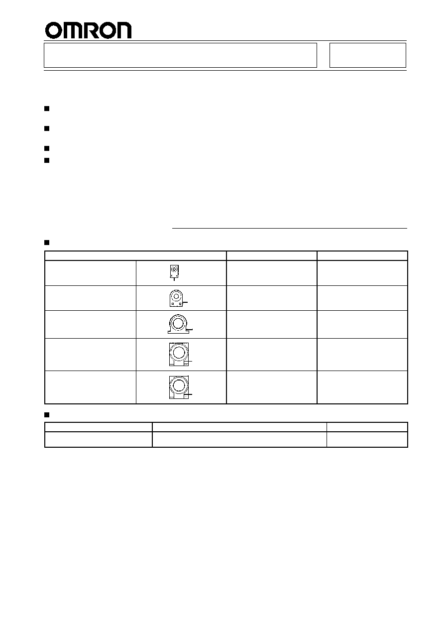
Sensor Heads
Sensor Head (non-shielded)
Min. object size
Model
10 dia.
0.3 dia. x 0.5 mm steel rod
F2LP-W10M
20 dia.
0.3 dia. x 1.0 mm steel rod
F2LP-W20M
50 dia.
2.0-dia. steel ball
F2LP-W50M
75 dia.
2.5-dia. steel ball
F2LP-W75M
100 dia.
3.0-dia. steel ball
F2LP-W100M
Amplifier Unit
Power supply
Output
Model
120/240 VAC, 50/60 Hz
Relay:
SPDT, 2 A, 250 VAC or 3 A, 30 VDC
DC Solid-state:
Photocoupler 100 mA max.
F2LP-WK4-US

F2LP-W
F2LP-W
2
Application Examples
Counting Falling Screws
Tank
F2LP-WK4-US
CQM1
F2LP-W50M
Specifications
Ratings/Characteristics
Sensor Units
Model
F2LP-W10M
F2LP-W20M
F2LP-W50M
F2LP-75M
F2LP-W100M
Sensing area
10 dia.
20 dia.
50 dia.
75 dia.
100 dia.
Sensing objects (see note 1)
Ferrous or non-ferrous moving metal object (Sensitivity lowers with non-ferrous metals).
Min. object size
0.3 dia. x 0.5 mm
steel rod
0.3 dia. x 1.0 mm
steel rod
2.0-dia. steel ball
2.5-dia. steel ball
3.0-dia. steel ball
Ambient temperature
Operating: --25
C to 70
C (with no icing)
Ambient humidity
Operating: 35% to 95%
Insulation resistance
50 M
min.
Head case and shield (0 V) are electrically connected.
Dielectric strength
1,000 VAC for
1 min.
Head case and shield (0 V) are electrically connected.
Vibration resistance
Durability: 10 to 55 Hz, 1.5 mm double amplitude for 2 hours each in X, Y, Z directions
Shock resistance
Durability: 500 m/s
2
(approx. 50G) for 3 times each in X, Y, Z directions
Cable (see note 2)
3 m (high-frequency coaxial cable)
Weight
Approx. 80 g
Approx. 220 g
Approx. 430 g
Approx. 800 g
Approx. 1,200 g
Enclosure rating
IEC IP67
Material
Case
Heat-resisting
ABS resin
Aluminum diecast
Sensing
surface
Heat-resisting ABS resin
Note: 1. The moving speed is based on the natural fall of objects from a height 10 cm above the Sensor.
2. The cable can be shortened or connected to another cable, as long as the total length of the cable is from 1.5 to 10 m. Use the
following cables for extension: F2LP-W10M, F2LP-W20M: Electrostatic capacity 97 nF/km; characteristic impedance 50 2
F2LP-W-50M, F2LP-W75M, F2LP-W100M: Electrostatic capacity 100 nF/km; characteristic
impedance 50 2

F2LP-W
F2LP-W
3
Amplifier Unit
Supply voltage
120/240 VAC 15%, 50/60 Hz
Power consumption
3 VA max.
Sensitivity adjustment
Selector and variable resistor
Timer
DC solid-state
Normal or 40-ms OFF delay. (selectable)
Relay
One-shot, 40 ms (fixed)
Sensing
interval
DC solid-state
Normal: 75 ms max.; OFF-delay: 125 ms max. (Minimum sensing objects can be detected at
intervals specified. Larger objects need longer intervals.)
interval
Relay
75 ms max. (See note for DC solid-state sensing interval.)
Control
DC solid-state
100 mA, 40 VDC max. photocoupler output; residual voltage: 2 V max. (Refer to Engineering Data.)
output
Relay
Resistive load of 2 A at 250 VAC or 3 A at 30 VDC
Compatibility with Sensor
Heads with different
diameters
Can be connected to F2LP-W
j
M Sensors with a diameter of 10, 20, 50, 75, or 100 (switchable).
Compensation for cord length
Switch setting
Output form
NO or NC (switchable)
Indicators
Power and operation
Ambient temperature
Operating: --10
C to 55
C (with no icing)
Ambient humidity
Operating: 35% to 85%
Insulation resistance
50 M
min. (at 500 VDC) between all live terminals and non-current carrying bare metal parts, and
between all primary terminals (for power supply) and all secondary terminals (for non-contact output
and Sensor)
Dielectric strength
1,500 VAC, 50/60 Hz for 1 minute between all live terminals and non-current carrying bare metal
parts, between all primary terminals (for power supply) and all secondary terminals (for non-contact
output and Sensor), and among all contact output terminals
Vibration resistance
Destruction: 10 to 55 Hz, 1.5 mm double amplitude for 2 hours in X, Y, Z directions respectively
Shock resistance
Destruction: 100 m/s
2
(approx. 10G) for 3 times in X, Y, Z directions respectively
Enclosure ratings
IEC IP30
Weight
Approx. 300 g
Engineering Data
Object Size vs. Falling Speed of Object (Typ.)
F2LP-W10M
F2LP-W20M
Object size (dia. x 0.5 mm)
Object size (dia. in 1 mm)
Iron
Aluminum
Object
Iron
Object
Heigh
t
Aluminum
S
peed
(
V
m/
s
)
S
peed
(
V
m/
s
)
Height
H
e
ight
(
m
)
H
e
ight
(
m
)

F2LP-W
F2LP-W
4
F2LP-W50M
Object size (dia. in mm)
F2LP-W75M
Object size (dia. in mm)
Iron
Brass
Object
Height
Sensing area
Iron
Brass
Object
Height
Sensing area
Object size (dia. in mm)
Residual Load Voltage Characteristics (Typ.)
Load current (mA)
F2LP-W100M
F2LP-WK4-US
Iron
Brass
Object
Height
S
peed
(
V
m/
s
)
S
peed
(
V
m/
s
)
S
peed
(
V
m/
s
)
Load
v
o
lt
age
(
v
)
H
e
ight
(
m
)
H
e
ight
(
m
)
H
e
ight
(
m
)
Operation
Amplifier Unit
Sensitivity selector
Timer mode selector (see note 1)
POWER indicator:
Lit when power is on.
OPERATION indicator:
Lit when sensing objects.
Frequency selector:
If induction or other mutual inter-
ference is experienced when us-
ing more than one Sensor, set the
Sensor to different frequencies.
Sensor selector:
F2LP-W10M, F2LP-W20M: Select dia.
of 10 to 20
F2LP-W50M, F2LP-W75M,
F2LP-W100M: Select dia. of 50 to 100
Compensation selector: Select the
position according to the cable length.
When cutting or extending the cable,
the length should be between 1.5 m
and 10 m.
Sensitivity adjustor
Output mode selector (see note 2)
240 VAC
120 VAC
--US
Note: 1. Timer mode selector: NORM:
No timer; TIMER: OFF-delay
transistor output (40 ms)
2. Output mode selector:
NO: Both transistor output and
relay output ON when sensing
objects; NC: Transistor output
OFF and relay output ON
when sensing objects

F2LP-W
F2LP-W
5
Timing Chart
Note: 1. Relay outputs are ON when ob-
jects are sensed (when objects
pass through the Sensor head)
2. Each relay output is ON for 40
ms minimum regardless of the
position of the timer mode se-
lector.
Sensing
Output mode
Timer mode
Transistor output
Relay output
OPERATION
indicator
POWER indicator
Object present
No object
NO
NC
OFF-delay
N
ORMAL
ON
OFF
ON
OFF
A: 40 ms (OFF-delay)
B: 40 ms (per detection)
When power is off
Lit
Not lit
Lit
Not lit
Dimensions
Note: All units are in millimeters unless otherwise indicated.
Sensor Heads
F2LP-W10M
4.1 dia., one-con-
ductor coaxial
cable (length: 3 m)
Two,
3.5-dia.
holes
10-dia. hole
F2LP-W20M
4.1 dia., one-
conductor coaxial
cable (length: 3 m)
Two, 4.5-dia. holes
20-dia. hole