 | –≠–ª–µ–∫—Ç—Ä–æ–Ω–Ω—ã–π –∫–æ–º–ø–æ–Ω–µ–Ω—Ç: G2R-1-E | –°–∫–∞—á–∞—Ç—å:  PDF PDF  ZIP ZIP |
Document Outline
- First Page
- Ordering Information
- Specifications
- Dimensions
- Contact Omron

1
Power PCB Relay
G2R
Power PCB Relay
G2R
∑ Creepage distance of 8.0 mm (0.31) min. between coil and
contact.
∑ Dual-winding latching type available.
∑ Plug-in and quick-connect terminals available.
∑ High sensitivity (360 mW) and high capacity (16 A) types
available.
∑ Highly stable magnetic circuit for latching endurance and
excellent resistance to vibration and shock.
∑ Safety-oriented design assuring high surge resistance:
10,000 V min. between coil and contacts.
∑ UL, CSA approved, marked with CE.
Ordering Information
To order: Select the part number and add the desired coil voltage rating (e.g., G2R-14-DC12).
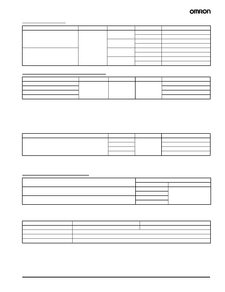
Non-Latching
1-Pole - PCB Types
1-Pole - Plug-in/Quick-connect Types
Note: 1. AgInSn and gold plated contacts available.
2. Bifurcated button available.
3. For individual product agency approvals consult factory.
4. Class B coil insulation available.
5. Push to test button available on plug-in type. Consult Omron for details.
6. CE mark only on plug-in and quick connect types (G2R- -S).
Type
Contact material
Contact form
Construction
Model
General purpose
AgCdO
SPDT
Semi-sealed
G2R-1
Sealed
G2R-14
SPST-NO
Semi-sealed
G2R-1A
Sealed
G2R-1A4
High-capacity
SPDT
Semi-sealed
G2R-1-E
SPST-NO
G2R-1A-E
High-sensitivity
SPDT
G2R-1-H
Sealed
G2R-14-H
SPST-NO
Semi-sealed
G2R-1A-H
Sealed
G2R-1A4-H
Type
Contact material
Contact form
Terminal
Model
General purpose
AgCdO
SPDT
Plug-in
G2R-1-S
LED indicator
G2R-1-SN
Surge suppression diode
G2R-1-SD
LED indicator and surge suppression diode
G2R-1-SND
Upper-mount bracket
SPDT
Quick connect
G2R-1-T
SPST-NO
G2R-1A-T
Power PCB Relay
G2R
2
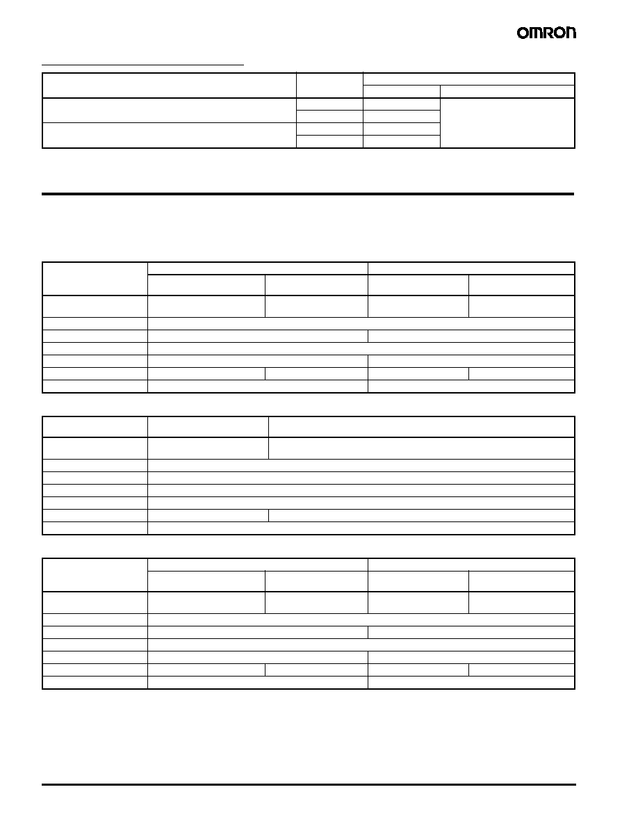
2-Pole - PCB Types
2 Pole - Plug-in/Quick-connect Types
Note: 1. AgInSn and gold plated contacts available.
2. Bifurcated button available.
3. For individual product agency approvals consult factory.
4. Class B coil insulation available.
5. Push to test button available on plug-in type. Consult Omron for details.
Latching
Accessories
Track Mounted Sockets/Track
Note: "-E" models are of finger-safe product construction. Round terminals cannot be used. Use Y-shaped terminals.
Screwless Clamp Terminal Socket Ordering Information
Note: For complete specifications see the data sheet at Omron's Knowledge center at www.knowledge.omron.com.
Type
Contact material
Contact form
Construction
Model
General purpose
AgCdO
DPDT
Semi-sealed
G2R-2
Sealed
G2R-24
DPST-NO
Semi-sealed
G2R-2A
Sealed
G2R-2A4
High sensitivity
DPDT
Semi-sealed
G2R-2-H
Sealed
G2R-24-H
DPST-NO
Semi-sealed
G2R-2A-H
Sealed
G2R-2A4-H
Type
Contact material
Contact form
Terminal
Model
General purpose
AgCdO
DPDT
Plug-in
G2R-2-S
LED indicator
G2R-2-SN
Surge suppression diode
G2R-2-SD
Led indicator and surge suppression diode
G2R-2-SND
Type
Contact form
Construction
Model
Dual coil latching
SPDT
Semi-sealed
G2RK-1
SPST-NO
G2RK-1A
DPDT
G2RK-2
DPST-NO
G2RK-2A
Relay
Model
Socket
Mounting track
G2R-1-S
(1-pole)
P2RF-05
PFP-100N or
PFP-50N and
PFP-M end plate
PFP-S (optional spacer)
P2RF-05-E
G2R-2-S
(2-pole)
P2RF-08
P2RF-08-E
1-pole
2-pole
Socket
P2RF-05-S
P2RF-08-S
Clip & release lever
P2CM-S
Nameplate
R99-11 nameplate for MY
Socket bridge
P2RM-SR, P2RM-SB
3
Power PCB Relay
G2R
Back Connecting Sockets/Plate
Specifications
Contact Data
Non-latching general purpose, plug-in, plug-in operation indicator self-contained, plug-in diode self-contained and
upper-mount bracket.
Non-latching high capacity 1-pole type
Non-latching high-sensitivity
Relay
Terminal
Model
Socket
Socket mounting plate
G2R-1-S
(1-pole)
Solder
P2R-05-A
P2R-P
PC
P2R-05P
G2R-2-S
(2-pole)
Solder
P2R-08A
PC
P2R-08P
Load
1-pole type
2-pole type
Resistive load
(p.f. = 1)
Inductive load
(p.f. = 0.4) (L/R = 7 ms)
Resistive load
(p.f. = 1)
Inductive load
(p.f. = 0.4) (L/R = 7 ms)
Rated load
10 A at 250 VAC
10 A at 30 VDC
7.5 A at 250 VAC
5 A at 30 VDC
5 A at 250 VAC
5 A at 30 VDC
2 A at 250 VAC
3 A at 30 VDC
Contact material
AgCdO
Carry current
10 A
5 A
Max. operating voltage
380 VAC, 125 VDC
Max. operating current
10 A
5 A
Max. switching capacity
2,500 VA, 300 W
1,875 VA, 150 W
1,250 VA, 150 W
500 VA, 90 W
Min permissible load
100 mA, 5 VDC
10 mA, 5 VDC
Load
Resistive load
(p.f. = 1)
Inductive load
(p.f. = 0.4) (L/R = 7 ms)
Rated load
16 A at 250 VAC
16 A at 30 VDC
8 A at 250 VAC
8 A at 30 VDC
Contact material
AgCdO
Carry current
16 A
Max. operating voltage
380 VAC, 125 VDC
Max. operating current
16 A
Max. switching capacity
4,000 VA, 480 W
2,000 VA, 240 W
Min. permissible load
100 mA, 5 VDC
Load
1-pole type
2-pole type
Resistive load
(p.f. = 1)
Inductive load
(p.f. = 0.4) (L/R = 7 ms)
Resistive load
(p.f. = 1)
Inductive load
(p.f. = 0.4) (L/R = 7 ms)
Rated load
5 A at 250 VAC
5 A at 30 VDC
2 A at 250 VAC
3 A at 30 VDC
3 A at 250 VAC
3 A at 30 VDC
1 A at 250 VAC
1.50 A at 30 VDC
Contact material
AgCdO
Carry current
5 A
3 A
Max. operating voltage
380 VAC, 125 VDC
Max. operating current
5 A
3 A
Max. switching capacity
1,250 VA, 150 W
500 VA, 90 W
750 VA, 90 W
250 VA, 45 W
Min permissible load
100 mA, 5 VDC
10 mA, 5 VDC

Power PCB Relay
G2R
4
Latching
Note: 1. P standard:
50
= 0.10 x 10
-6
operation.
2. AgInSn contacts available.
3. For individual product agency approvals consult factory.
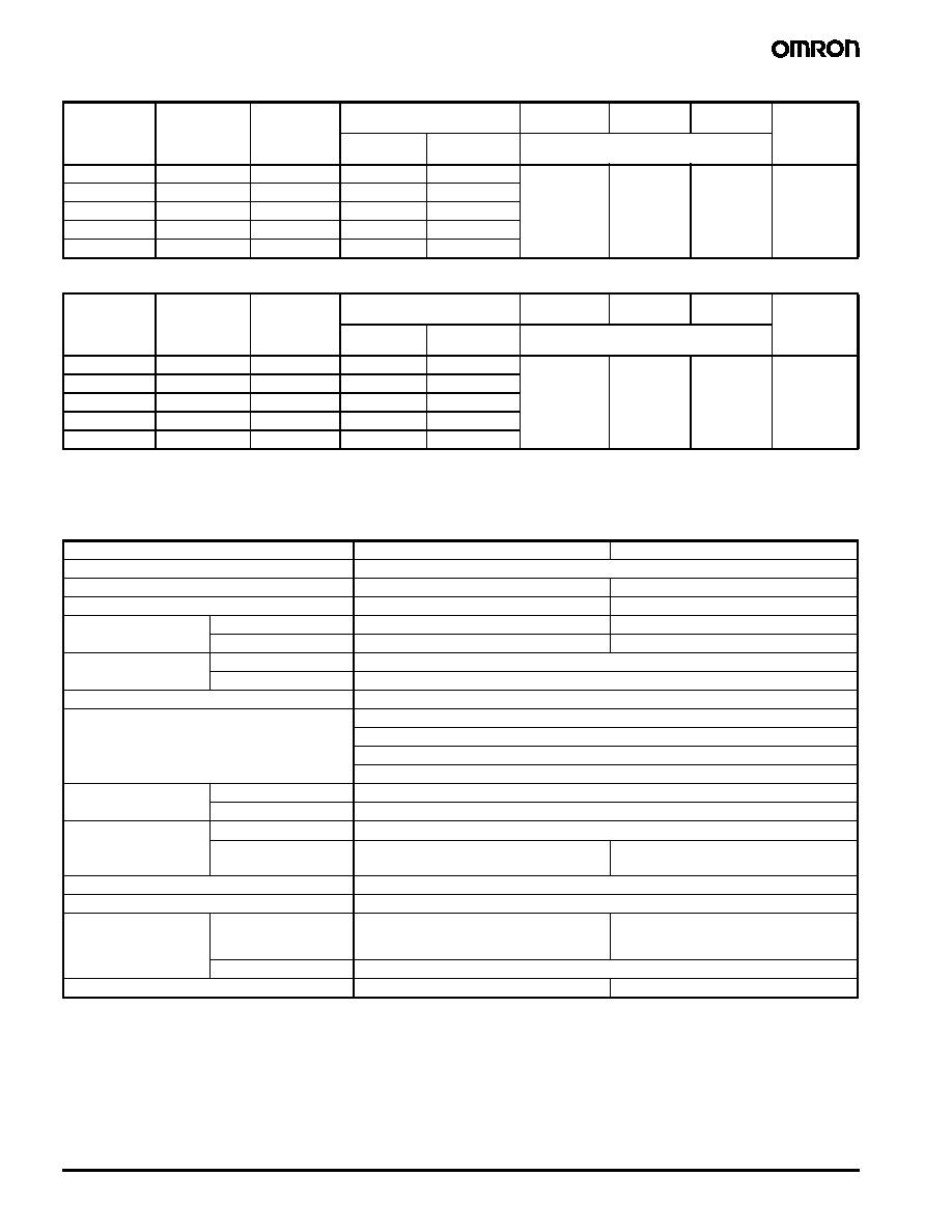
Coil Data
Non-latching DC coil
Non-latching AC coil
Non-latching high-sensitivity DC coil
Load
1-pole type
2-pole type
Resistive load
(p.f. = 1)
Inductive load
(p.f. = 0.4) (L/R = 7 ms)
Resistive load
(p.f. = 1)
Inductive load
(p.f. = 0.4) (L/R = 7 ms)
Rated load
5 A at 250 VAC
5 A at 30 VDC
3.50 A at 250 VAC
2.50 A at 30 VDC
3 A at 250 VAC
3 A at 30 VDC
1.50 A at 250 VAC
2 A at 30 VDC
Contact material
AgCdO
Carry current
5 A
3 A
Max. operating voltage
380 VAC, 125 VDC
Max. operating current
5 A
3 A
Max. switching capacity
1,250 VA, 150 W
875 VA, 75 W
750 VA, 90 W
375 VA, 60 W
Min permissible load
100 mA, 5 VDC
10 mA, 5 VDC
Rated voltage
(VDC)
Rated current
(mA)
Coil
resistance
(
)
Coil inductance
(ref. value) (H)
Pick-up
voltage
Dropout
voltage
Maximum
voltage
Power
consumption
(mW)
Armature
OFF
Armature
ON
% of rated voltage
3
176
17
0.07
0.14
70% max.
15% min.
110% max.
at 70
∞C
(158
∞F)
Approx. 530
5
106
47
0.20
0.39
6
88.20
68
0.28
0.55
12
43.60
275
1.15
2.29
24
21.80
1,100
4.27
8.55
48
11.50
4,170
13.86
22.71
100
5.30
18,860
67.20
93.20
110
4.80
22,900
81.50
110.60
Rated voltage
(VDC)
Rated current
(mA)
Coil
resistance
(
)
Coil inductance
(ref. value) (H)
Pick-up
voltage
Dropout
voltage
Maximum
voltage
Power
consumption
(mW)
Armature
OFF
Armature
ON
% of rated voltage
6
150
16
0.05
0.10
80% max.
30% min.
110% max.
at 70
∞C
(158
∞F)
Approx. 0.9
12
75
65
0.19
0.39
24
37.50
260
0.81
1.55
50
18
1,130
3.25
6.73
110
10.60
4,600
13.34
26.84
120
7.50
6,500
21
42
220
5.30
22,000
51.30
102
240
3.80
30,000
65.50
131
Rated voltage
(VDC)
Rated current
(mA)
Coil
resistance
(
)
Coil inductance
(ref. value) (H)
Pick-up
voltage
Dropout
voltage
Maximum
voltage
Power
consumption
(mW)
Armature
OFF
Armature
ON
% of rated voltage
3
120
25
0.13
0.26
70% max.
15% min.
110% max.
at 70
∞C
(158
∞F)
Approx. 360
5
71.40
70
0.37
0.75
6
60
100
0.63
1.07
12
30
400
2.14
4.27
24
15
1,600
7.80
15.60
48
7.50
6,400
31.20
62.40
5
Power PCB Relay
G2R
Latching dual coil type - Set coil
Latching dual coil type - Reset coil
Note: 1. The rated current and coil resistance are measured at a coil temperature of 23
∞C (73∞F) with a tolerance of ±10%.
2. The operating characteristics are measured at a coil temperature of 23
∞C (73∞F).
Characteristics
Note: Data shown are of initial value.
Rated voltage
(VDC)
Rated current
(mA)
Coil
resistance
(
)
Coil inductance
(ref. value) (H)
Pick-up
voltage
Dropout
voltage
Maximum
voltage
Power
consumption
(mW)
Armature
OFF
Armature
ON
% of rated voltage
3
227
10.80
0.026
0.052
70% max.
70% max.
110% max.
at 70
∞C
(158
∞F)
Approx. 850
5
167
30
0.073
0.146
6
138
43.50
0.104
0.208
12
70.60
170
0.42
0.83
24
34.60
694
1.74
3.43
Rated voltage
(VDC)
Rated current
(mA)
Coil
resistance
(
)
Coil inductance
(ref. value) (H)
Pick-up
voltage
Dropout
voltage
Maximum
voltage
Power
consumption
(mW)
Armature
OFF
Armature
ON
% of rated voltage
3
200
15
0.001
0.002
70% max.
70% max.
110% max.
at 70
∞C
(158
∞F)
Approx. 600
5
119
42
0.003
0.006
6
100
60
0.005
0.009
12
50
240
0.018
0.036
24
25
960
0.079
0.148
Item
Non-latching
Latching
Contact resistance
100 m
Operate (set) time
15 ms. max.
20 ms max.
Release (reset) time
AC: 10 ms max.; DC: 5 ms max.
20 ms max.
Bounce time
Operate
---
Mean value approx. 3 ms
Release
---
Mean value approx. 8 ms
Operating frequency
Mechanical
18,000 operations/hour
Electrical
1,800 operations/hour (under rated load)
Insulation resistance
1,000 M
min. (at 500 VDC)
Dielectric strength
5,000 VAC, 50/60 Hz for 1 minute between coil and contacts
1,000 VAC, 50/60 Hz for 1 minute across contacts of same pole
3,000 VAC, 50/60 Hz for 1 minute between contact sets, 2-pole non-latching
1,000 VAC, 50/60 Hz for 1 minute between set and reset coils of dual coil latching
Vibration
Mechanical durability
10 to 55 Hz; 1.50 mm (0.06) double amplitude
Malfunction durability
10 to 55 Hz; 1.50 mm (0.06) double amplitude
Shock
Mechanical durability
1,000 m/s
2
(approx. 100G)
Malfunction durability
200 m/s
2
(approx. 20 G) when energized
100 m/s
2
(approx. 10 G) when de-energized
500 m/s
2
(approx. 50 G) at set
100 m/s
2
(approx. 10 G) at reset
Ambient temperature
-40 to 70
∞C (-40 to 158∞F)
Humidity
35% to 85% RH
Service life
Mechanical
AC: 10,000,000 operations min.
DC: 20,000,000 operations min.
(at 18,000 operations/hour)
10,000,000 operations min.
(at 18,000 operations/hour)
Electrical
See "Characteristics Data"
Weight
Approx. 17 g (0.60 oz.)
Approx. 17 g (0.60 oz.)