s
Creepage distance of 8.0 mm (0.31 in) min.
between coil and contact
s
Dual-winding latching type available
s
Plug-in and quick-connect terminals available
s
High sensitivity (360 mW) and high
capacity (16 A) types available
s
Highly stable magnetic circuit for latching
endurance and excellent resistance to vibra-
tion and shock
s
Continuous coil rating
s
Safety-oriented design assuring high surge
resistance: 10,000 V min. between coil and
contacts
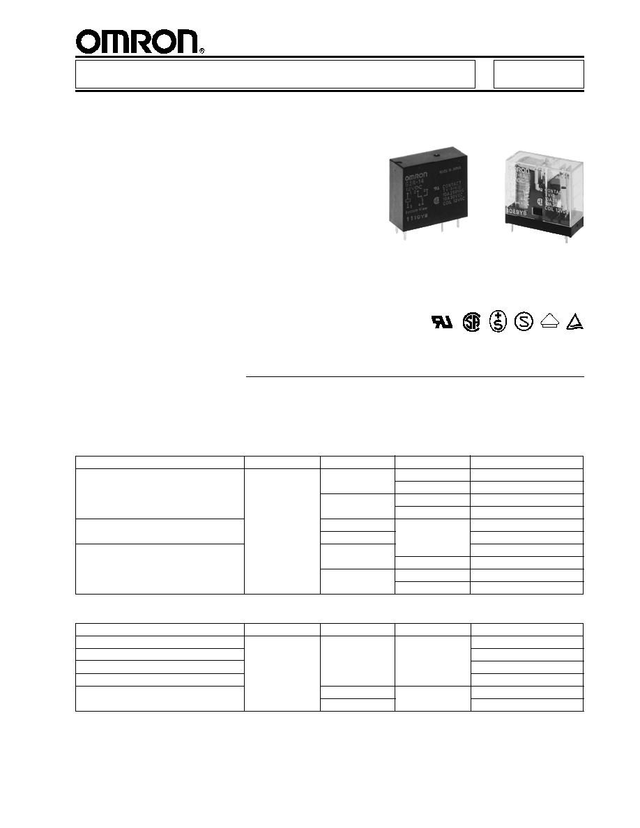
Power PCB Relay
G2R
Ordering Information
Type
Contact material
Contact form
Construction
Part number
General purpose
AgCdO
SPDT
Semi-sealed
G2R-1
Sealed
G2R-14
SPST-NO
Semi-sealed
G2R-1A
Sealed
G2R-1A4
High capacity
SPDT
Semi-sealed
G2R-1-E
SPST-NO
G2R-1A-E
High sensitivity
SPDT
G2R-1-H
Sealed
G2R-14-H
SPST-NO
Semi-sealed
G2R-1A-H
Sealed
G2R-1A4-H
To Order: Select the part number and add the desired coil voltage rating (e.g., G2R-14-
DC12).
s
NON-LATCHING
s
LATCHING
1-Pole ≠ PCB types
Type
Contact material
Contact form
Terminal
Part number
General purpose
AgCdO
SPDT
Plug-in
G2R-1-S
LED indicator
G2R-1-SN
Surge suppression diode
G2R-1-SD
LED indicator and surge suppression diode
G2R-1-SND
Upper-mount Bracket
SPDT
Quick Connect
G2R-1-T
SPST-NO
G2R-1A-T
1-Pole ≠ Plug-in/Quick-connect types
Note:
1. AgInSn and gold plated contacts available.
2. Bifurcated button available.
3. For individual product agency approvals consult factory.
4. Class B coil insulation available.
D
V
E

2
G2R
G2R
Type
Contact material
Contact form
Terminal
Part number
General purpose
AgCdO
DPDT
Plug-in
G2R-2-S
LED indicator
G2R-2-SN
Surge suppression diode
G2R-2-SD
LED indicator and surge suppression diode
G2R-2-SND
Type
Contact material
Contact form
Construction
Part number
General Purpose
AgCdO
DPDT
Semi-sealed
G2R-2
Sealed
G2R-24
DPST-NO
Semi-sealed
G2R-2A
Sealed
G2R-2A4
High Sensitivity
DPDT
Semi-sealed
G2R-2-H
Sealed
G2R-24-H
DPST-NO
Semi-sealed
G2R-2A-H
Sealed
G2R-2A4-H
s
NON-LATCHING (continued)
s
LATCHING
2-Pole ≠ PCB types
2-Pole ≠ Plug-in/Quick-connect types
Note:
1. AgInSn and gold plated contacts available.
2. Bifurcated button available.
3. For individual product agency approvals consult factory.
4. Class B coil insulation available.
Type
Contact form
Construction
Part number
Dual coil latching
SPDT
Semi-sealed
G2RK-1
SPST-NO
G2RK-1A
DPDT
G2RK-2
DPST-NO
G2RK-2A
Part number
Relay
Socket
Mounting track
G2R-1-S
s s
s s
(1-pole)
P2RF-05-E
PFP-100N or
G2R-2-S
s s
s s
(2-pole)
P2RF-08-E
PFP-50N and
PFP-M end plate
PFP-S (optional spacer)
s
ACCESSORIES
Track mounted sockets/tracks
Back connecting sockets/plate
Part number
Relay
Terminal
Socket
Socket mounting plate
G2R-1-S
s s
s s
(1-pole)
Solder
P2R-05A
P2R-P
PC
P2R-05P
G2R-2-S
s s
s s
(2-pole)
Solder
P2R-08A
PC
P2R-08P
3
G2R
G2R
Specifications
s
CONTACT DATA
Non-latching general purpose, plug-in, plug-in operation indicator self-contained, plug-in diode self-contained, and
upper-mount bracket
1-pole type
2-pole type
Resistive load
Inductive load
Resistive load
Inductive load
Load
(p.f. = 1)
(p.f. = 0.4) (L/R = 7 ms)
(p.f. = 1)
(p.f. = 0.4) (L/R = 7 ms)
Rated load
10 A at 250 VAC
7.5 A at 250 VAC
5 A at 250 VAC
2 A at 250 VAC
10 A at 30 VDC
5 A at 30 VDC
5 A at 30 VDC
3 A at 30 VDC
Contact material
AgCdO
Carry current
10 A
5 A
Max. operating voltage
380 VAC, 125 VDC
Max. operating current
10 A
5 A
Max. switching capacity
2,500 VA, 300 W
1,875 VA, 150 W
1,250 VA, 150 W
500 VA, 90 W
Min. permissible load
100 mA, 5 VDC
10 mA, 5 VDC
Non-latching high capacity 1-pole type
Resistive load
Inductive load
Load
(p.f. = 1)
(p.f. = 0.4) (L/R = 7 ms)
Rated load
16 A at 250 VAC
8 A at 250 VAC
16 A at 30 VDC
8 A at 30 VDC
Contact material
AgCdO
Carry current
16 A
Max. operating voltage
380 VAC, 125 VDC
Max. operating current
16 A
Max. switching capacity
4,000 VA, 480 W
2,000 VA, 240 W
Min. permissible load
100 mA, 5 VDC
1-pole type
2-pole type
Resistive load
Inductive load
Resistive load
Inductive load
Load
(p.f. = 1)
(p.f. = 0.4) (L/R = 7 ms)
(p.f. = 1)
(p.f. = 0.4) (L/R = 7 ms)
Rated load
5 A at 250 VAC
2 A at 250 VAC
3 A at 250 VAC
1 A at 250 VAC
5 A at 30 VDC
3 A at 30 VDC
3 A at 30 VDC
1.50 A at 30 VDC
Contact material
AgCdO
Carry current
5A
3 A
Max. operating voltage
380 VAC, 125 VDC
Max. operating current
5 A
3 A
Max. switching capacity
1,250 VA, 150 W
500 VA, 90 W
750 VA, 90 W
250 VA, 45 W
Min. permissible load
100 mA, 5 VDC
10 mA, 5 VDC
Non-latching high-sensitivity
1-pole type
2-pole type
Resistive load
Inductive load
Resistive load
Inductive load
Load
(p.f. = 1)
(p.f. = 0.4) (L/R = 7 ms)
(p.f. = 1)
(p.f. = 0.4) (L/R = 7 ms)
Rated load
5 A at 250 VAC
3.50 A at 250 VAC
3 A at 250 VAC
1.50 A at 250 VAC
5 A at 30 VDC
2.50 A at 30 VDC
3 A at 30 VDC
2 A at 30 VDC
Contact material
AgCdO
Carry current
5A
3 A
Max. operating voltage
380 VAC, 125 VDC
Max. operating current
5 A
3 A
Max. switching capacity
1,250 VA, 150 W
875 VA, 75 W
750 VA, 90 W
375 VA, 60 W
Min. permissible load
100 mA, 5 VDC
10 mA, 5 VDC
Latching
Note:
1. P standard:
50
= 0.10 x 10
-6
operation.
2. AgInSn contacts available.
3. For individual product agency approvals consult factory.
5
G2R
G2R
Note:
1. The rated current and coil resistance are measured at a coil temperature of 23
∞
C (73
∞
F) with a tolerance of
±
10%.
2. The operating characteristics are measured at a coil temperature of 23
∞
C (73
∞
F).
s
COIL DATA (continued)
Latching dual coil type - Set coil
Non-latching
Latching
Contact resistance
one-pole: 30 m
max.; 2-pole: 50 m
max.
Operate (set) time
15 ms max.
20 ms max.
Release (reset) time
AC: 10 ms max.; DC: 5 ms max.
20 ms max.
Bounce time
Operate
--
Mean value approx. 3 ms
Release
--
Mean value approx. 8 ms
Operating
Mechanical
18,000 operations/hour
frequency
Electrical
1,800 operations/hour (under rated load)
Insulation resistance
1,000 M
min. (at 500 VDC)
Dielectric strength
5,000 VAC, 50/60 Hz for 1 minute between coil and contacts
1,000 VAC, 50/60 Hz for 1 minute across contacts of same pole
3,000 VAC, 50/60 Hz for 1 minute between contact sets, 2-pole non-latching
1,000 VAC, 50/60 Hz for 1 minute between set and reset coils of dual coil latching
Vibration
Mechanical durability
10 to 55 Hz; 1.50 mm (0.06 in) double amplitude
Malfunction durability
10 to 55 Hz; 1.50 mm (0.06 in) double amplitude
Shock
Mechanical durability
1,000 m/s
2
(approx. 100 G)
Malfunction durability
200 m/s
2
(approx. 20 G) when energized
500 m/s
2
(approx. 50 G) at set
100 m/s
2
(approx.10 G) when de-energized 100 m/s
2
(approx. 10 G) at reset
Ambient temperature
-40 to 70
∞
C (-40
∞
to 158
∞
F)
Humidity
35% to 85% RH
Service life
Mechanical
AC: 10,000,000 operations min.
10,000,000 operations min.
DC: 20,000,000 operations min.
(at 18,000 operations/hour)
(at 18,000 operations/hour)
Electrical
See "Characteristic Data"
Weight
Approx. 17 g (0.60 oz)
Approx. 17 g (0.60 oz)
Note: Data shown are of initial value.
s
CHARACTERISTICS
Coil inductance
Set
Reset
Rated
Rated
Coil
(ref. value) (H)
pick-up
dropout
Maximum
Power
voltage
current
resistance
Armature
Armature
voltage
voltage
voltage
consumption
(VDC)
(mA)
(
)
OFF
ON
% of rated voltage
(mW)
3
227
10.80
0.026
0.052
70% max.
70% max.
110% max.
Approx. 850
5
167
30
0.073
0.146
at 70
∞
C
6
138
43.50
0.104
0.208
(158
∞
F)
12
70.60
170
0.42
0.83
24
34.60
694
1.74
3.43
Latching dual coil type - Reset coil
Coil inductance
Set
Reset
Rated
Rated
Coil
(ref. value) (H)
pick-up
dropout
Maximum
Power
voltage
current
resistance
Armature
Armature
voltage
voltage
voltage
consumption
(VDC)
(mA)
(
)
OFF
ON
% of rated voltage
(mW)
3
200
15
0.001
0.002
70% max.
70% max.
110% max.
Approx. 600
5
119
42
0.003
0.006
at 70
∞
C
6
100
60
0.005
0.009
(158
∞
F)
12
50
240
0.018
0.036
24
25
960
0.079
0.148
