
4
PCB Relay
G2RL
Next-generation PCB Relay Available in
24 Models
Low profile: 15.7 mm max. in height
Contains no lead inside and features cadmium-free
contacts ensuring environment-friendly use.
Conforms to VDE0435 (VDE approval: C250
insulation grade for flux protection models; B400
insulation grade for fully sealed models), UL508
and CSA22.2.
Meets VDE0700 requirements for household
products according to VDE0110.
Clearance and creepage distance: 10 mm/10 mm.
Tracking resistance: CTI>250
(Both standard and class F type)
UL1446 Class F Coil Insulation system available.
High sensitivity: 400 mW
R
C
VDE
Ordering Information
Classification
Enclosure
ti
Contact form
C ass ca o
c osu e
ratings
SPST-NO
SPDT
DPST-NO
DPDT
Standard
General-purpose
Flux protection
G2RL-1A
G2RL-1
G2RL-2A
G2RL-2
S a da d
Ge e a
u ose
Fully sealed
G2RL-1A4
G2RL-14
G2RL-2A4
G2RL-24
High-capacity
Flux protection
G2RL-1A-E
G2RL-1-E
---
---
g ca ac y
Fully sealed
G2RL-1A4-E
G2RL-14-E
---
---
Class-F
General-purpose
Flux protection
G2RL-1A-CF
G2RL-1-CF
G2RL-2A-CF
G2RL-2-CF
C ass
Ge e a
u ose
Fully sealed
G2RL-1A4-CF
G2RL-14-CF
G2RL-2A4-CF
G2RL-24-CF
High-capacity
Flux protection
G2RL-1A-E-CF
G2RL-1-E-CF
---
---
g ca ac y
Fully sealed
G2RL-1A4-E-CF
G2RL-14-E-CF
---
---
Rated coil voltage
Note:
When ordering, add the rated coil voltage to the model number.
Example: G2RL-1A 12 VDC
Model Number Legend
G2RL-
jjj
-
j
-
j
1
2
3
4
5
1.
Number of Poles
1:
1 pole
2:
2 poles
2.
Contact Form
None:
j
PDT
A:
j
PST-NO
3.
Enclosure Ratings
None: Flux protection
4:
Fully sealed
4.
Classification
None: General purpose
E:
High capacity (1 pole)
5.
Approved Standards
None: UL, CSA, VDE, UL Class B Insulation
CF:
UL, CSA, VDE, UL Class F Insulation

G2RL
G2RL
5
Specifications
Coil Ratings
Rated voltage
5 VDC
12 VDC
24 VDC
48 VDC
Rated current
80.0 mA
33.33 mA
16.7 mA
8.96 mA
Coil resistance
62.5
360
1,440
5,358
Coil inductance (H)
(
f
l
)
Armature OFF
0.18
1.01
4.19
15.91
Coil inductance (H)
(ref. value)
Armature ON
0.44
2.47
9.72
33.65
Must operate voltage
70% max. of the rated voltage
Must release voltage
10% min. of the rated voltage
Max. voltage
130% at 85
�
C of the rated voltage
Power consumption
Approx. 400 mW
Approx. 430 mW
Contact Ratings
Number of poles
1 pole
2 poles
Contact material
AgSnO
2
AgNi
Load
Resistive load (cos
=1)
Resistive load (cos
=1)
Rated load
12 A (16 A) at 250 VAC
12 A (16 A) at 24 VDC
(See note 2.)
8 A at 250 VAC
8 A at 30 VDC
(See note 2.)
Rated carry current
12 A (16 A)
(See note 2.)
8 A (70
�
C)/5 A (85
�
C)
(See note 2.)
Max. operating voltage
440 VAC, 300 VDC
Max. operating current
12 A (16 A)
8 A
Max. switching power
3,000 VA (4,000 VA)
2,000 VA
Note:
1. Values in parentheses are those for the high-capacity model.
2. Contact your OMRON representative for the ratings on fully sealed models.
Characteristics
Item
1 pole
2 poles
Contact resistance
100 m
max.
Operate (set) time
Approx. 7 ms
Release (reset) time
Approx. 2 ms
Max. operating frequency
Mechanical: 18,000 operation/hr
Electrical:
1,800 operation/hr at rated load
Insulation resistance
1,000 M
min. (at 500 VDC)
Dielectric strength
5,000 VAC, 1 min between coil and contacts
1,000 VAC, 1 min between contacts of same polarity
5,000 VAC, 1 min between coil and contacts
2,500 VAC, 1 min between contacts of different polarity
1,000 VAC, 1 min between contacts of same polarity
Impulse withstand voltage
10 kV (1.2
50
�
s) between coil and contact
Vibration resistance
Destruction:
10 to 55 Hz, 1.5-mm double amplitude
Malfunction:
10 to 55 Hz, 1.5-mm double amplitude
Shock resistance
Destruction:
1,000 m/s
2
Malfunction:
Energized:
100 m/s
2
Not energized:
100 m/s
2
Life expectancy (Mechanical)
20,000,000 operations (at 18,000 operations/hr)
Ambient temperature
Operating:
�40
�
C to 85
�
C (with no icing)
Storage:
�40
�
C to 85
�
C (with no icing)
Ambient humidity
35% to 85%
Weight
Approx. 12 g
Packaging
Standard: 20 relays/stick
Approved Standards
UL508 (File No. E41515)
Model
Contact form
Coil ratings
Contact ratings
G2RL-1A
SPST-NO
3 to 48 VDC
12 A at 250 VAC (General use)
12 A t 24 VDC (R
i ti
)
G2RL-1
SPDT
3 to 48 VDC
12 A at 250 VAC (General use)
12 A at 24 VDC (Resistive)
G2RL-1A-E
SPST-NO (High capacity)
16 A at 250 VAC (General use)
16 A t 24 VDC (R
i ti
)
G2RL-1-E
SPDT (High capacity)
16 A at 250 VAC (General use)
16 A at 24 VDC (Resistive)
G2RL-2A
DPST-NO
8 A at 277 VAC (General use)
8 A t 30 VDC (R
i ti
)
G2RL-2
DPDT
8 A at 277 VAC (General use)
8 A at 30 VDC (Resistive)
G2RL
G2RL
6
CSA C22.2 (No. 14) (File No. LR31928)
Model
Contact form
Coil ratings
Contact ratings
G2RL-1A
SPST-NO
3 to 48 VDC
12 A at 250 VAC (General use)
12 A t 24 VDC (R
i ti
)
G2RL-1
SPDT
3 to 48 VDC
12 A at 250 VAC (General use)
12 A at 24 VDC (Resistive)
G2RL-1A-E
SPST-NO (High capacity)
16 A at 250 VAC (General use)
16 A t 24 VDC (R
i ti
)
G2RL-1-E
SPDT (High capacity)
16 A at 250 VAC (General use)
16 A at 24 VDC (Resistive)
G2RL-2A
DPST-NO
8 A at 277 VAC (General use)
8 A t 30 VDC (R
i ti
)
G2RL-2
DPDT
8 A at 277 VAC (General use)
8 A at 30 VDC (Resistive)
VDE (VDE0435)
Model
Contact form
Coil ratings
Contact ratings
G2RL
1 pole
5, 12, 18, 22, 24, 48 VDC
12 A at 250 VAC (cos
=1)
12 A at 24 VDC (L/R=0 ms)
AC15: 3 A at 240 VAC
DC13: 2.5 A at 24 VDC, 50 ms
1 pole (High capacity)
16 A at 250 VAC (cos
=1)
16 A at 24 VDC (L/R=0 ms)
AC15: 3 A at 240 VAC (NO)
1.5 A at 240 VAC (NC)
DC13: 2.5 A at 24 VDC (NO), 50 ms
2 poles
8 A at 250 VAC (cos
=1)
8 A at 24 VDC (L/R=0 ms)
AC15: 1.5 A at 240 VAC
DC13: 2 A at 30 VDC, 50 ms
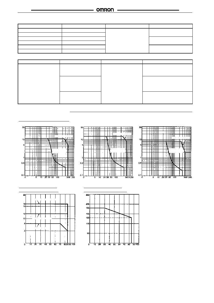
Engineering Data
DC resistive
load
AC resistive load
Maximum Switching Capacity
Switching Current (A)
Switching voltage (V)
Ambient Temperature
vs Maximum Coil Voltage
Maximum Coil V
oltage (%)
Ambient Temperature (
�
C)
Ambient Temperature
vs Rated Carry Current
Rated Carry Current (A)
Ambient Temperature (
�
C)
G2RL-2A, G2RL-2
G2RL-1A-E, G2RL-1-E
G2RL-1A, G2RL-1
G2RL-1A, G2RL-1
G2RL-1A-E, G2RL-1-E
G2RL-2A, G2RL-2
Switching voltage (V)
Switching voltage (V)
Switching Current (A)
Switching Current (A)
Note:
The maximum coil voltage refers to
the maximum value in a varying
range of operating power voltage,
not a continuous voltage.
DC resistive
load
AC resistive load
DC resistive
load
AC resistive load
85
Note:
Contact your OMRON representative for the data on fully sealed models.

G2RL
G2RL
7
Electrical Life Data
G2RL-1-E
16 A at 250 VAC (cos
=1)
30,000 operations min.
16 A at 24 VDC
30,000 operations min.
8 A at 250 VAC (cos
=0.4)
200,000 operation min.
(NO side operation)
8 A at 30 VDC (L/R=7 ms)
10,000 operation min.
G2RL-1
12 A at 250 VAC (cos
=1)
50,000 operations min.
12 A at 24 VDC
30,000 operations min.
5 A at 250 VAC (cos
=0.4)
150,000 operation min.
5 A at 30 VDC (L/R=7 ms)
20,000 operation min.
G2RL-2
8 A at 250 VAC (cos
=1)
30,000 operations min.
8 A at 30 VDC
30,000 operations min.
G2RL-1A-E
Pilot duty (A300), 250 VAC
250,000 operations min.
Pilot duty (A300), 125 VAC
150,000 operations min.
Note:
The results shown reflect values measured using very severe test conditions i.e., Duty: 1 sec ON/1 sec OFF.
Electrical life will vary depending on the test conditions. Contact your OMRON representative if you require more detailed information
for the electrical life under your test conditions.
Dimensions
Note:
All units are in millimeters unless otherwise indicated.
*
Indicates average
dimensions.
G2RL-1A, G2RL-1A4
Four, 1.3
�
0.1 dia.
holes
Mounting Holes
(Bottom View)
Terminal Arrangement/
Internal Connection
(Bottom View)
3
4
5
1
(2.5)
Five, 1.3
�
0.1 dia.
holes
Mounting Holes
(Bottom View)
Terminal Arrangement/
Internal Connection
(Bottom View)
*
Indicates average
dimensions.
G2RL-1, G2RL-14
1
3
4
5
2
(2.5)
Six, 1.3
�
0.1 dia.
holes
Mounting Holes
(Bottom View)
Terminal Arrangement/
Internal Connection
(Bottom View)
*
Indicates average
dimensions.
G2RL-1A-E, G2RL-1A4-E
4
5
3
6
1
8
(2.5)

G2RL
G2RL
8
Eight, 1.3
�
0.1 dia.
holes
Mounting Holes
(Bottom View)
Terminal Arrangement/
Internal Connection
(Bottom View)
*
Indicates average
dimensions.
G2RL-1-E, G2RL-14-E
1
8
2
7
3
6
4
5
(2.5)
Six, 1.3
�
0.1 dia.
holes
Mounting Holes
(Bottom View)
Terminal Arrangement/
Internal Connection
(Bottom View)
*
Indicates average
dimensions.
G2RL-2A, G2RL-2A4
1
8
3
6
4
5
(2.5)
Eight, 1.3
�
0.1 dia.
holes
Mounting Holes
(Bottom View)
Terminal Arrangement/
Internal Connection
(Bottom View)
*
Indicates average
dimensions.
G2RL-2, G2RL-24
1
8
2
7
3
6
4
5
(2.5)
Precautions
Basic Information
Before actually committing any component to a mass-production
situation, OMRON strongly recommends situational testing, in as
close to actual production situations as possible. One reason is to
confirm that the product will still perform as expected after surviving
the many handling and mounting processes involved in mass pro-
duction. Also, even though OMRON relays are individually tested a
number of times, and each meets strict requirements, a certain test-
ing tolerance is permissible. When a high-precision product uses
many components, each depends upon the rated performance
thresholds of the other components. Thus, the overall performance
tolerance may accumulate into undesirable levels. To avoid prob-
lems, always conduct tests under the actual application conditions.
General
To maintain the initial characteristics of a relay, exercise care that it
is not dropped or mishandled. For the same reason, do not remove
the case of the relay; otherwise, the characteristics may degrade.
Avoid using the relay in an atmosphere containing sulfuric acid
(SO
2
), hydrogen sulfide (H
2
S), or other corrosive gases. Do not
continuously apply a voltage higher than the rated maximum volt-
age to the relay. Never try to operate the relay at a voltage and a cur-
rent other than those rated.
Do not use the relay at temperatures higher than that specified in the
catalog or data sheet.
OMRON Corporation
C&C Components Division H.Q.
Relay Division
28F, Crystal Tower Bldg.,
1-2-27, Shiromi, Chuo-ku,
Osaka 540-6028 Japan
Tel: (81)6-6949-6125 Fax: (81)6-6949-6134
ALL DIMENSIONS SHOWN ARE IN MILLIMETERS.
To convert millimeters into inches, multiply by 0.03937. To convert grams into ounces, multiply by 0.03527.
Cat. No. J117-E1-1
In the interest of product improvement, specifications are subject to change without notice.
Printed in Japan
0999-1M (0999)