 | –≠–ª–µ–∫—Ç—Ä–æ–Ω–Ω—ã–π –∫–æ–º–ø–æ–Ω–µ–Ω—Ç: G2RL-1A | –°–∫–∞—á–∞—Ç—å:  PDF PDF  ZIP ZIP |
Document Outline
- First Page
- Ordering Information
- Specifications
- Electrical Life Data
- Engineering Data
- Dimensions
- Contact Omron Information

PCB Relay
G2RL
1
PCB Relay
G2RL
High Capacity, Low Profile Relay
D
Low profile: 15.7 mm max. in height.
D
Cadmium-free contacts ensuring environment-friendly
use.
D
10 kV impulse surge withstand.
D
Clearance and creepage distance:
10 mm/10 mm.
D
Tracking resistance: CTI>250.
D
Choose from UL Class-B or Class-F insulation systems.
D
Low coil power of 400 mW.
D
UL, CSA and VDE approved.
VDE
Ordering Information
Classification
Enclosure ratings
Contact form
g
SPST-NO
SPDT
DPST-NO
DPDT
Model
Class-B
General-purpose
Flux protection
G2RL-1A
G2RL-1
G2RL-2A
G2RL-2
p p
Fully sealed
G2RL-1A4
G2RL-14
G2RL-2A4
G2RL-24
High-capacity
Flux protection
G2RL-1A-E
G2RL-1-E
---
---
g
p
y
Fully sealed
G2RL-1A4-E
G2RL-14-E
---
---
Class-F
General-purpose
Flux protection
G2RL-1A-CF
G2RL-1-CF
G2RL-2A-CF
G2RL-2-CF
p p
Fully sealed
G2RL-1A4-CF
G2RL-14-CF
G2RL-2A4-CF
G2RL-24-CF
High-capacity
Flux protection
G2RL-1A-E-CF
G2RL-1-E-CF
---
---
g
p
y
Fully sealed
G2RL-1A4-E-CF G2RL-14-E-CF
---
---
Note: When ordering, add the rated coil voltage to the part number. Example: G2RL-1A DC12
J
MODEL NUMBER LEGEND
G2RL-jjj-j-j
1
2
3
4
5
1. Number of Poles
1:
1 pole
2:
2 poles
2. Contact Form
None: jPDT
A:
j
PST-NO
3. Enclosure Ratings
None: Flux protection (vented)
4:
Fully sealed (with "knock off vent nib")
4. Classification
None: General purpose
E:
High capacity (1 pole)
5. Approved Standards
None: UL, CSA, VDE, UL Class B Insulation
CF:
UL, CSA, VDE, UL Class F Insulation
2
PCB Relay
G2RL
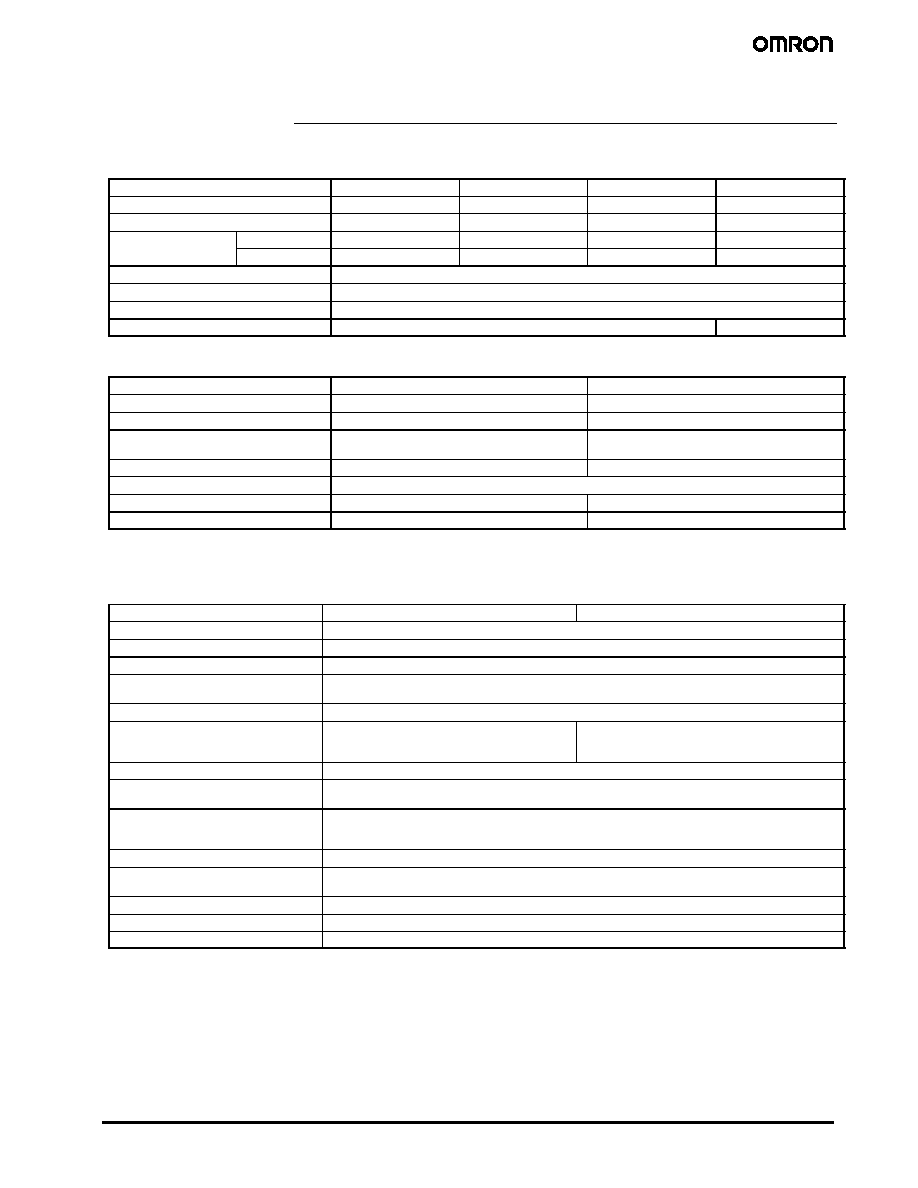
Specifications
J
COIL RATINGS
Rated voltage
5 VDC
12 VDC
24 VDC
48 VDC
Rated current
80.0 mA
33.33 mA
16.7 mA
8.96 mA
Coil resistance
62.5
360
1,440
5,358
Coil inductance (H) (ref.
l )
Armature OFF
0.18
1.01
4.19
15.91
Co
duc a ce ( ) ( e
value)
Armature ON
0.44
2.47
9.72
33.65
Must operate voltage
70% max. of the rated voltage
Must release voltage
10% min. of the rated voltage
Max. voltage
130% of the rated voltage (at 85∞C )
Power consumption
Approx. 400 mW
Approx. 430 mW
J
CONTACT RATINGS
Number of poles
1 pole
2 poles
Contact material
AgSnO
2
AgNi
Load
Resistive load (cos=1)
Resistive load (cos=1)
Rated load
12 A (16 A) at 250 VAC
12 A (16 A) at 24 VDC
8 A at 250 VAC
8 A at 30 VDC
Rated carry current
12 A (16 A)
8 A (70∞C)/5 A (85∞C)
Max. operating voltage
440 VAC, 300 VDC
Max. operating current
12 A (16 A)
8 A
Max. switching power
3,000 VA (4,000 VA), 288 W (384 W)
2,000 VA, 240 W
Note: Values in parentheses are those for the high-capacity model.
J
CHARACTERISTICS
Item
1 pole
2 poles
Contact resistance
100 m max.
Operate (set) time
Approx. 7 ms
Release (reset) time
Approx. 2 ms
Max. operating frequency
Mechanical: 18,000 operation/hr
Electrical:
1,800 operation/hr at rated load
Insulation resistance
1,000 M min. (at 500 VDC)
Dielectric strength
5,000 VAC, 1 min between coil and contacts
1,000 VAC, 1 min between contacts of same polarity
5,000 VAC, 1 min between coil and contacts
2,500 VAC, 1 min between contacts of different polarity
1,000 VAC, 1 min between contacts of same polarity
Impulse withstand voltage
10 kV (1.2◊50 µs) between coil and contact
Vibration resistance
Destruction:
10 to 55 Hz, 1.5-mm double amplitude
Malfunction:
10 to 55 Hz, 1.5-mm double amplitude
Shock resistance
Destruction:
1,000 m/s
2
Malfunction:
Energized:
100 m/s
2
Not energized:
100 m/s
2
Life expectancy (Mechanical)
20,000,000 operations (at 18,000 operations/hr)
Ambient temperature
Operating:
--40∞C to 85∞C (with no icing)
Storage:
--40∞C to 85∞C (with no icing)
Ambient humidity
35% to 85%
Weight
Approx. 12 g
Packaging
Standard: 20 relays/stick
3
PCB Relay
G2RL
J
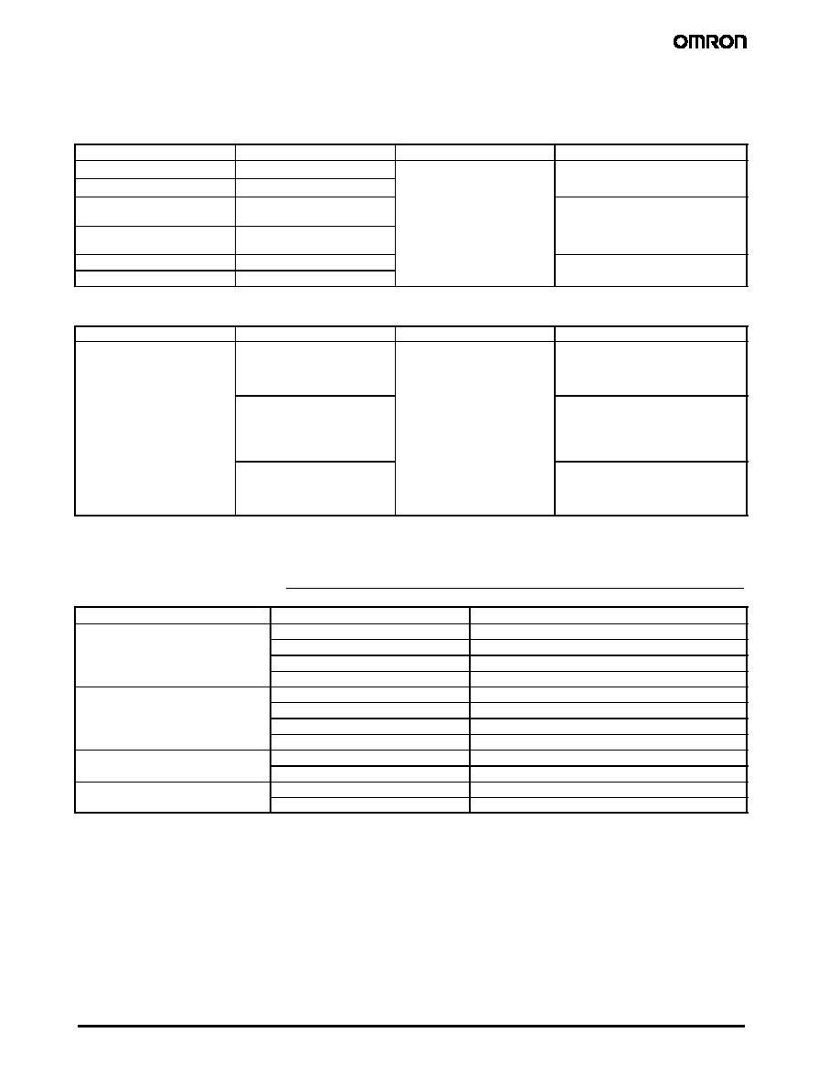
APPROVED STANDARDS
UL508 (File No. E41643)/CSA C22.2 (No.14) (File No. LR31928)
Part number
Contact form
Coil ratings
Contact ratings
G2RL-1A
SPST-NO
3 to 48 VDC
12 A at 250 VAC (General use), 100k ops.
12 A at 24 VDC (Resistive) 50k ops
G2RL-1
SPDT
12 A at 24 VDC (Resistive), 50k ops.
1/3 hp, 120 VAC, 30k ops., 60_C
G2RL-1A-E
SPST-NO (High capacity)
16 A at 250 VAC (General use), 100k ops.
16 A at 24 VDC (Resistive), 50k ops.
20 A at 240 VAC (General use) 85_C
G2RL-1-E
SPDT (High capacity)
20 A at 240 VAC (General use), 85_C
15 A at 240 VAC (General use), 105_C
1/2 hp, 120 VAC, 100k ops., 70_C (NO)
G2RL-2A
DPST-NO
8 A at 277 VAC (General use), 100k ops.
8 A t 30 VDC (R i ti ) 100k
G2RL-2
DPDT
8
a
C (Ge e a use), 00 ops
8 A at 30 VDC (Resistive), 100k ops.
VDE (VDE0435)
Part number
Contact form
Coil ratings
Contact ratings
G2RL
1 pole
5, 12, 18, 22, 24, 48 VDC
12 A at 250 VAC (cos=1)
12 A at 24 VDC (L/R=0 ms)
AC15: 3 A at 240 VAC
DC13: 2.5 A at 24 VDC, 50 ms
1 pole (High capacity)
16 A at 250 VAC (cos=1)
16 A at 24 VDC (L/R=0 ms)
AC15: 3 A at 240 VAC (NO)
1.5 A at 240 VAC (NC)
DC13: 2.5 A at 24 VDC (NO), 50 ms
2 poles
8 A at 250 VAC (cos=1)
8 A at 24 VDC (L/R=0 ms)
AC15: 1.5 A at 240 VAC
DC13: 2 A at 30 VDC, 50 ms
Note: To achieve approved life cycles on sealed models, the relay should be vented by removing "knock off vent nib" on top of relay case
after the soldering/washing process.
Electrical Life Data
Part number
Contact rating
Minimum operations
G2RL-1-E
16 A at 250 VAC (cos=1)
100,000 operations min. (1 sec. ON / 9 sec. OFF)
G
16 A at 24 VDC
30,000 operations min.
8 A at 250 VAC (cos=0.4)
200,000 operations min. (N.O. side operation)
8 A at 30 VDC (L/R=7 ms)
10,000 operations min.
G2RL-1
12 A at 250 VAC (cos=1)
100,000 operations min. (1 sec. ON / 9 sec. OFF)
G
12 A at 24 VDC
30,000 operations min.
5 A at 250 VAC (cos=0.4)
150,000 operations min.
5 A at 30 VDC (L/R=7 ms)
20,000 operations min.
G2RL-2
8 A at 250 VAC (cos=1)
100,000 operations min. (1 sec. ON / 9 sec. OFF)
G
8 A at 30 VDC
30,000 operations min.
G2RL-1A-E
Pilot duty (A300), 250 VAC
250,000 operations min. (1 sec. ON / 9 sec OFF)
G
Pilot duty (A300), 125 VAC
150,000 operations min. (1 sec. ON / 9 sec OFF)
Note: 1. The results shown reflect minimum cycles using a very severe duty cycle of 1 sec ON/1 sec OFF (unless otherwise specified
above).
2. In order to obtain the full rated life cycles on the fully sealed models, the relay should be properly vented by removing the
"knock off vent nib" on top of the relay case after the soldering / washing process of the P.C.B.
Contact Omron for applications where venting of the sealed relay is not possible.
5
PCB Relay
G2RL
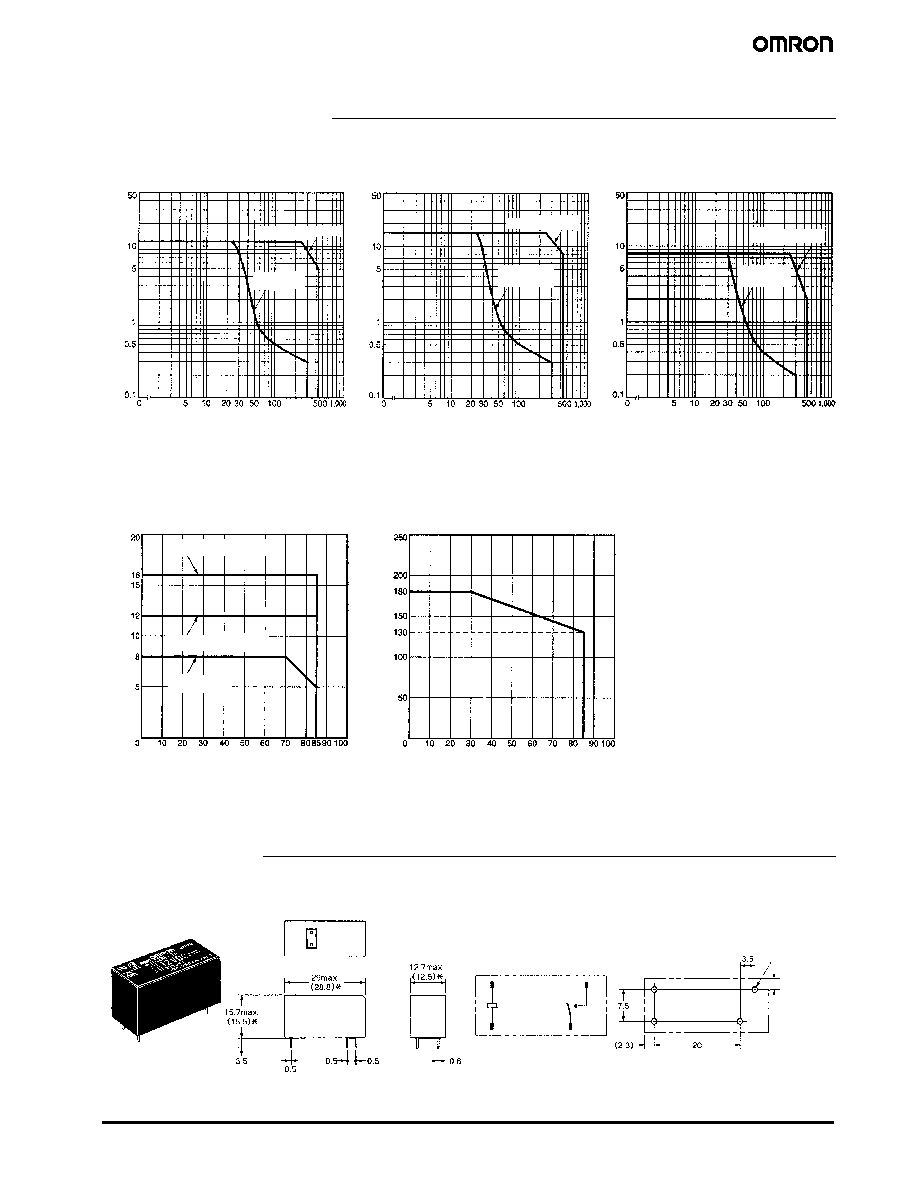
Engineering Data
DC resistive
load
AC resistive load
J
MAXIMUM SWITCHING CAPACITY
Switching voltage (V)
J
AMBIENT TEMPERATURE
VS MAXIMUM COIL VOLTAGE
Ambient Temperature (∞C)
J
AMBIENT TEMPERATURE
VS RATED CARRY CURRENT
Ambient Temperature (∞C)
G2RL-2A, G2RL-2
G2RL-1A-E, G2RL-1-E
G2RL-1A, G2RL-1
G2RL-1A, G2RL-1
G2RL-1A-E, G2RL-1-E
G2RL-2A, G2RL-2
Switching voltage (V)
Switching voltage (V)
Note: The maximum coil voltage refers to the maximum value in a varying range of operating power voltage, not a continuous voltage.
DC resistive
load
AC resistive load
DC resistive
load
AC resistive load
85
Switching
c
urrent
(A)
Switching
c
urrent
(A)
Switching
c
urrent
(A)
Rated
c
arry
current
(A)
Minimum
c
oil
v
oltage
(%)
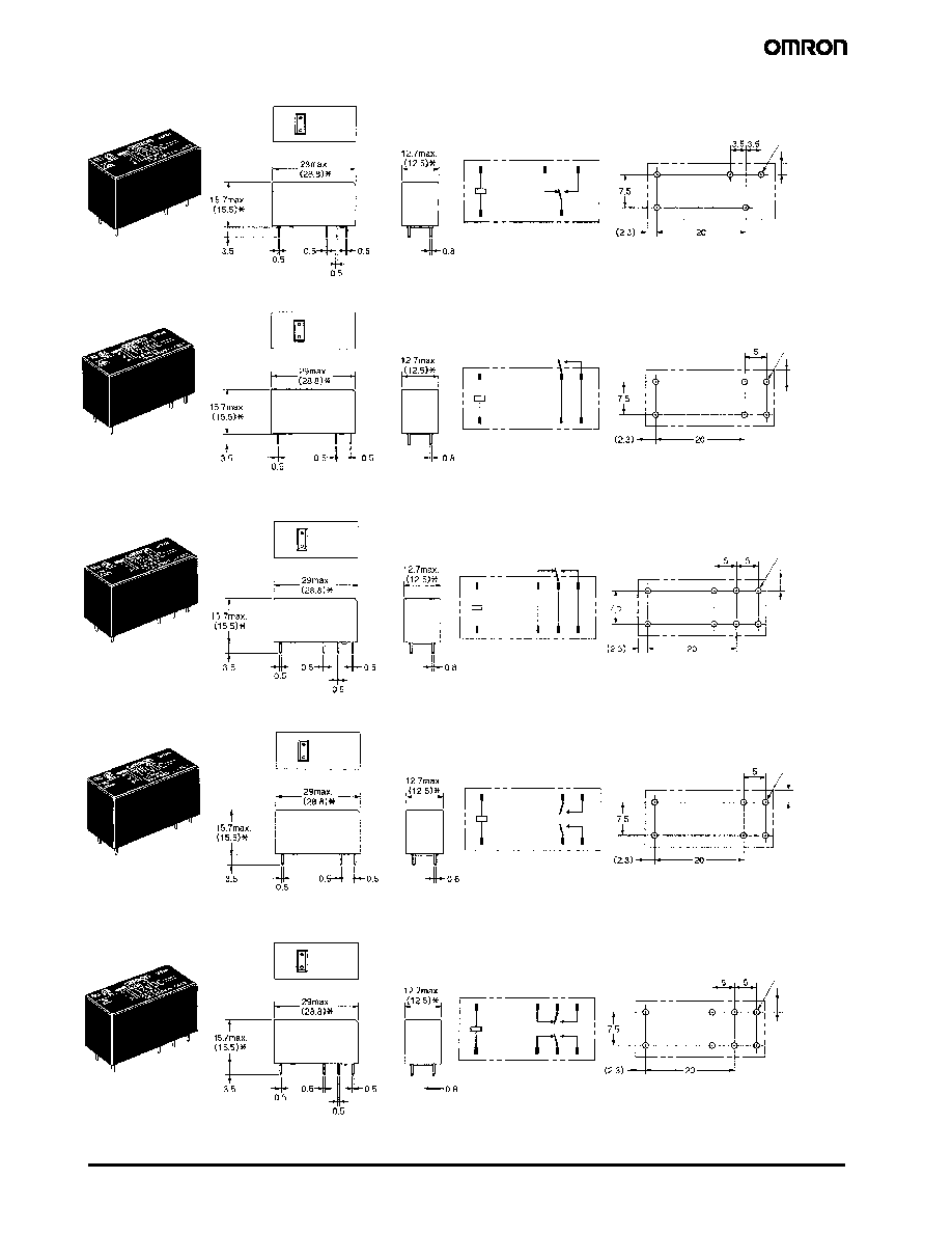
Dimensions
Unit: mm (inch)
* Indicates average
dimensions.
G2RL-1A, G2RL-1A4
Four, 1.3±0.1 dia.
holes
Mounting Holes
(Bottom View)
Terminal Arrangement/
Internal Connection
(Bottom View)
3
4
5
1
(2.5)
240
PCB Relay
G2RL
Five, 1.3±0.1 dia.
holes
Mounting Holes
(Bottom View)
Terminal Arrangement/
Internal Connection
(Bottom View)
* Indicates average
dimensions.
G2RL-1, G2RL-14
1
3
4
5
2
(2.5)
Six, 1.3±0.1 dia.
holes
Mounting Holes
(Bottom View)
Terminal Arrangement/
Internal Connection
(Bottom View)
* Indicates average
dimensions.
G2RL-1A-E, G2RL-1A4-E
4
5
3
6
1
8
(2.5)
Eight, 1.3±0.1 dia.
holes
Mounting Holes
(Bottom View)
Terminal Arrangement/
Internal Connection
(Bottom View)
* Indicates average
dimensions.
G2RL-1-E, G2RL-14-E
1
8
2
7
3
6
4
5
(2.5)
Six, 1.3±0.1 dia.
holes
Mounting Holes
(Bottom View)
Terminal Arrangement/
Internal Connection
(Bottom View)
* Indicates average
dimensions.
G2RL-2A, G2RL-2A4
1
8
3
6
4
5
(2.5)
Eight, 1.3±0.1 dia.
holes
Mounting Holes
(Bottom View)
Terminal Arrangement/
Internal Connection
(Bottom View)
* Indicates average
dimensions.
G2RL-2, G2RL-24
1
8
2
7
3
6
4
5
(2.5)