
38
Power MOS FET Relay
G3DZ
SSR Identical to the G6D in Size with a
Maximum AC/DC Switching Current of
0.6 A
Switching 0.6 A at 240 VAC or 100 VDC.
10-
µ
A current leakage max. between open output
terminals.
2,500-VAC dielectric strength ensured between
input and output terminals.
Input resistor and varistor incorporated.
Switching full- and half-wave rectified alternating
currents.
Ordering Information
Model Number Legend:
G3DZ -
1
2
3
4
1. Load Voltage
2:
A load voltage of 240 VAC
2. Load Current
R6: A load current of 0.6 A
3. Terminal
P:
PCB terminal
4. Zero Cross Function
L:
Without zero cross function
Contact form
Insulation
Zero cross
function
Indicator
Applicable output
load
Rated input
voltage
Model
SPST-NO
Photodiode array
No
No
0.6 A at
5 VDC
G3DZ-2R6PL
3 to 264 VAC
12 VDC
3 to 125 VDC
24 VDC
Accessories (Order Separately)
See "
Dimensions" for details.
Connecting socket
P6D-04P
Back

G3DZ
G3DZ
39
Specifications
Ratings
Input
Rated voltage
Operating voltage
Input impedance
Voltage level
Must operate
Must release
5 VDC
4 to 6 VDC
830
±
20%
4 VDC max.
1 VDC min.
12 VDC
9.6 to 14.4 VDC
2 k
±
20%
9.6 VDC max.
24 VDC
19.2 to 28.8 VDC
4 k
±
20%
19.2 VDC max.
Output
Load voltage
Load current
Inrush current
3 to 264 VAC, 3 to 125 VDC
100
µ
A to 0.6 A
6 A (10 ms)
Characteristics
Operate time
6 ms max.
Release time
10 ms max.
Output ON-resistance
2.4
max.
Leakage current
10
µ
A max. (at 125 VDC)
Insulation resistance
100 M
min. (at 500 VDC)
Dielectric strength
2,500 VAC, 50/60 Hz for 1 min between input and output
Vibration resistance
Malfunction: 10 to 55 Hz, 1.5-mm double amplitude
Shock resistance
Malfunction: 1,000 m/s
2
(approx. 100G)
Ambient temperature
Operating: ≠30
∞
C to 85
∞
C (with no icing)
Storage:
≠30
∞
C to 100
∞
C (with no icing)
Ambient humidity
Operating: 45% to 85%
Weight
Approx. 3.1 g
G3DZ
G3DZ
40
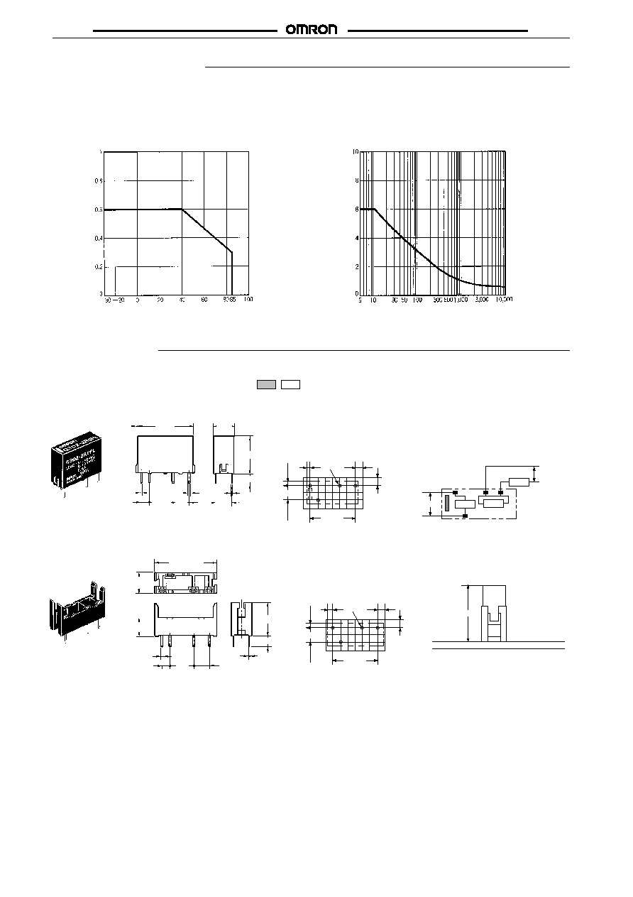
Engineering Data
Load Current vs. Ambient Temperature
Characteristics
G3DZ-2R6PL
Inrush Current Resistivity
Non-repetitive (Keep the inrush current to half the rated value
if it occurs repetitively.)
G3DZ-2R6PL
Load current (A)
Inrush current (A. Peak)
Ambient temperature (
∞
C)
Energizing time (ms)
Dimensions
Note:
1. All units are in millimeters unless otherwise indicated.
2. Orientation marks are indicated as follows:
G3DZ-2R6PL
Terminal Arrangement/
Internal Connections
(Bottom View)
Mounting Holes
(Bottom View)
Tolerance:
±
0.1
P6D-04P Connecting Socket
17.5
0.5
0.5
2.54
7.62
5.08
0.8
6.5
12.5 max.
3.5
5.08
0.3
Load
Load
power
supply
Input
Load
Input voltage
15.24
5.08
(0.71)
2.54
2.54
(1.13)
Four, 1.1 dia.
7
5
1
13
+
≠
≠
+
19.7 max.
6.9 max.
6
±
0.1
0.65
2.54
7.62
5.08
0.3
3.6
10.8
18.5 mm max.
15.24
5.08
(0.86)
2.54
2.54
(2.18)
Four, 1.1 dia.
Mounting Holes
(Bottom View)
Tolerance:
±
0.1
Socket Mounting Height

G3DZ
G3DZ
41
Precautions
If any reversed surge voltage is imposed on the input terminals, in-
sert a diode in parallel to the input terminals as shown in the follow-
ing circuit diagram and do not impose a reversed voltage value of
3 V or more.
Input
13
+
≠
1
5
7
Load
Load Connection
When connecting a load generating a high inrush current (such as a
lamp load) to the MOS FET Relay, make sure that the MOS FET
Relay can withstand the inrush current.
OMRON's datasheets show the non-repetitive peak value of the
MOS FET Relay's inrush current durability. Normally allow 1/2 of
this inrush current to flow through the MOS FET Relay. If an inrush
current exceeding that value is expected, connect a quick-blowing
fuse to protect the MOS FET Relays.
AC Load
No zero cross function is incorporated.
The maximum operating frequency is 10 Hz.
Forwarding/Reversing Control of Single-phase Inductive
Motor
Use a MOS FET Relay with an output voltage twice as large as the
supply voltage. Contact your OMRON representative before using
MOS FET Relays with 200 V output.
MOS
FET
Relay
+
≠
+
≠
SW1
SW2
Input
Input
Motor
Load power
supply
MOS
FET
Relay
Operate SW1 for at least 30 ms after SW2 has been operated, or
vice versa.
Capacitive Load
1. Use a MOS FET Relay with an output voltage twice as large
as the supply voltage because the supply voltage and charge
voltage of the capacitor are imposed on the MOS FET Relay
at the same time when the MOS FET Relay is turned OFF.
2. Limit the charge voltage of the capacitor to 1/2 of the peak
inrush current value that is allowed to flow into the MOS FET
Relay.
Handling Instructions
Handle the G3DZ with care so that the G3DZ will not be damaged
due to static electricty.
DC Load
If a coil load such as a solenoid or electromagnetic valve is con-
nected to the G3DZ, connect a diode in parallel to the load to absorb
counter-electromotive force.
Input
Load
MOS
FET
Relay
For high-speed operation:
Input
Load
MOS
FET
Relay
To shorten the time, connect a Zener diode and a regular diode in
series as shown in the illustration above.
The G3DZ switches full-wave rectified alternating currents, half-
wave rectified alternating currents, and low capacity load currents.
AC/DC Load
DC Load
+
≠
+
DC
Load
AC
MOS
FET
Input
≠
Load
MOS
FET
Input
≠
DC
≠
+
+
≠
Load
Load
Relay
Relay
Load power
supply
Or
Or
+
If an inductive AC load is connected to the G3DZ, connect a varistor
as a surge absorber in parallel to the load.
+
≠
Load
MOS
FET
Input
Load
Relay
Although the G3DZ has a built-in varistor connected to the load ter-
minals of the G3DZ to absorb noise, do not wire power lines or high-
tension lines along with the lines connected to the G3DZ in a single
duct or the G3DZ may be damaged or malfunction due to induction.
The surge absorption element must satisfy the following require-
ments.
Operating voltage
Varistor voltage
Inrush resistance
100 to 120 VAC
240 to 270 V
1,000 A min.
Operating voltage
Varistor voltage
Inrush resistance
200 to 240 VAC
440 to 470 V
1,000 A min.