Document Outline
- First Page
- Ordering Information
- Specifications
- Dimensions
- Precautions
- Contact Omron
1
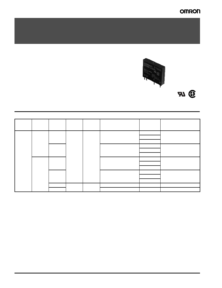
Solid State Relay
G3MB
Solid State Relay
G3MB
Low cost Subminiature PCB mounting
2 amp Single in-line package (SIP) SSR
∑ Bottom is approximately 3 times smaller than G3M.
∑ Low cost "SIP" package switches up to 2A loads.
∑ Built in Snubber circuit and input resistor as option.
∑ Two footprints available for design flexibility.
∑ The G3MB-202PEG-4-DC20MA crosses directly to the
Motorola M0C2A-60 series power triac.
Ordering Information
To Order: Specify input voltage at end of part number. Example: G3MB-202P-DC24
Note: 1. For versions without input voltage specified, a current limiting resistor must be placed in series with the input. See LED drive specifications
and recommendations below.
2. TUV versions available. Contact your local Omron representative.
Isolation
Output
terminal
pitch
Zero
cross
Input
resistor
Built-in
snubber
circuit
Rated output
load
Rated
input
voltage
Model
Phototriac
7.62 mm
Yes
Yes
Yes
2 A at 100 to 240 VAC
5 VDC
G3MB-202P
12 VDC
24 VDC
No
2 A at 100 to 240 VAC
5 VDC
G3MB-202PL
12 VDC
24 VDC
5.08 mm
Yes
2 A at 100 to 240 VAC
5 VDC
G3MB-202P-4
12 VDC
24 VDC
No
2 A at 100 to 240 VAC
5 VDC
G3MB-202PL-4
12 VDC
24 VDC
Yes
No
No
2 A at 100 to 240 VAC
N/A *
(See Note)
G3MB-202PEG-4-DC20MA
No
2 A at 100 to 240 VAC
N/A *
(See Note)
G3MB-202PLEG-4-DC20MA
Solid State Relay
G3MB
2
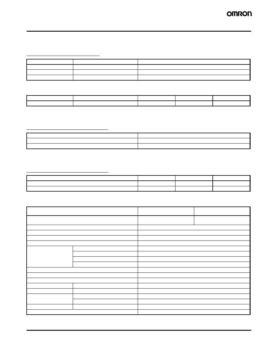
Specifications
Input Rating
Models with Input Resistor
Output Rating
LED Drive Data
Models without Input Resistor
Recommended LED Operating Conditions
Models without Input Resistor
Characteristics
Note: Data shown are of initial value.
Rated voltage
Operating range
Input impedance
5 VDC
4 to 6 VDC
440
±20%
12 VDC
9.60 to 14.40 VDC
1k
±20%
24 VDC
19.20 to 28.80 VDC
2.20k
±20%
Model
Rated load voltage
Load voltage range
Load current
Surge current
G3MB-202
100 to 240 VAC
75 to 264 VAC
0.10 to 2 A
30 A (60 Hz, 1 cycle)
LED forward current
50 mA max.
Repetitive peak LED forward current
1 A max.
LED reverse voltage
5 V max.
Min.
Standard
Max.
LED forward current
5 mA
10 mA
20 mA
Must drop voltage
0
--
1 V
Type
G3MB-202P
G3MB-202PEG
G3MB-202PL
G3MB-202PLEG
Operate time
1/2 of load power source
cycle + 1 ms max.
1 ms max.
Release time
1/2 of load power source cycle + 1 ms max.
Output ON voltage drop
1.60 V (RMS) max.
Leakage current
1 mA max. at 100 VAC, 1.50 mA at 200 VAC
Non-repetitive peak surge
30 A
Output
PIV (V
DRM
)
600 V
di/dt
40 A/µs
dv/dt
100 V/µs
I
2
t
4 A
2
s
Junction temperature (Tj)
125∞C (257∞F) max.
Insulation resistance
1,000 M
min. at 500 VDC
Dielectric strength
2500 VAC, 50/60 Hz for 1 minute; 3750 VAC max., 1 second
Vibration
Malfunction
10 to 55 Hz, 0.75 mm (0.03 in) double amplitude, approx. 5 G
Shock
Malfunction
Approx. 100 G
Ambient temperature
Operating
-30∞ to 80∞C (-22∞ to 176∞F) with no icing
Storage
-30∞ to 100∞C (-22∞ to 212∞F) with no icing
Humidity
Operating
45% to 85% RH
Weight
Approx. 5 g (0.18 oz)

3
Solid State Relay
G3MB
Characteristic Data
Dimensions
Unit: mm (inch)
Relays
Load current vs. ambient
Inrush current resistivity
temperature characteristics
Non-repetitive (Keep the inrush current to
half the rated value if it occurs repetitively.)
Switching current (A)
Inr
ush current (A P
eak)
10
30 50 100 300 500 1,000
100
0
10
20
30
40
5,000 10,000
Ambient temperature ∞C
Switching current (A)
-40
-20
0
20 25 40
60
100
0
0.5
1.0
1.5
2.0
2.5
80
PCB Dimensions
(Bottom view)
20.5
(0.81)
max.
3.9 (0.15)
2.54 (0.10)
24.5 (0.96)
max.
0.7
(0.03)
1.4 (0.06)
0.4 (0.02)
5.5
(0.22)
max
Terminal Arrangement/
Internal Connections
(Bottom view)
INPUT
LOAD
4 (-) 3 (+)
2
1
7.62
(0.30)
2.54
(0.1)
2.54 (0.1)
Four 1.0 (0.04) dia.
G3MB
2.54
(0.1)
2.54 (0.1)
Four 1.0 (0.04) dia.
G3MB (-4)
Solid State Relay
G3MB
4
Approvals
UL (File No. E64562)
CSA (File No. LR35535)
Note: 1. The rated values approved by each of the safety standards (e.g., UL and CSA) may be different from the performance characteristics
individually defined in this catalog.
2. In the interest of product improvement, specifications are subject to change.
Precautions
See General Information Section near the back of this catalog for
Solid State Precautions.
Soldering must be completed within 10 seconds at 260
∞C or less.
Make sure that the space between the bottom of the relay and the
PCB is 0.1 mm or less. When making holes on the PCB for the
relay's edge terminals, the hole diameters should be slightly smaller
than the actual diameters of the edge terminals. This will reduce
unnecessary space between the bottom of the relay and the PCB.
To use the SSR output for phase control, select a model that does
not incorporate a zero-cross function.
The SSR case serves to dissipate heat. When mounting more than
three SSRs as a group, pay attention to the ambient temperature rise
and install the Relays so that they are adequately ventilated. If poor
ventilation is unavoidable, reduce the load current by half.
Protective Component
The input circuitry does not incorporate a circuit protecting the SSR
from being damaged due to a reversed connection. Make sure that
the polarity is correct when connecting the input lines.
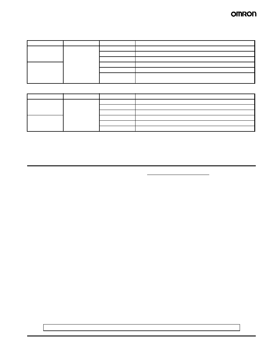
SSR Type
Input voltage
Load type
Load ratings
G3MB-102P
5 to 24 VDC
General purpose
2 A, 120 VAC
Tungsten
1 A, 120 VAC
Motor
1.60 FLA/9.60 LRA, 120 VAC
G3MB-202P
General purpose
2 A, 240 VAC
G3MB-202PL
Tungsten
1 A, 240 VAC
G3MB-202PEG
Motor
1.60 FLA/9.60 LRA, 240 VAC
G3MB-202PLEG
SSR Type
Input voltage
Load type
Load ratings
G3MB-102P
5 to 24 VDC
General purpose
2 A, 120 VAC
Tungsten
1 A, 120 VAC
Motor
1.60 FLA/8.60 LRA, 120 VAC
G3MB-202P
General purpose
2 A, 240 VAC
G3MB-202PL
Tungsten
1 A, 240 VAC
Motor
1.60 FLA/8.60 LRA, 240 VAC
ALL DIMENSIONS SHOWN ARE IN MILLIMETERS. To convert millimeters into inches, divide by 25.4

5
Solid State Relay
G
3MB
OMRON ON-LINE
Global - http://www.omron.com
USA - http://www.omron.com/oei
Canada - http://www.omron.ca
ALL DIMENSIONS SHOWN ARE IN MILLIMETERS. To convert millimeters into inches, divide by 25.4
Cat. No. GC RLY8
5/03 Specifications subject to change without notice Printed in USA
OMRON CANADA, INC.
885 Milner Avenue
Toronto, Ontario M1B 5V8
416-286-6465
OMRON ELECTRONICS LLC
One Commerce Drive
Schaumburg, IL 60173
847-882-2288