1
Solid-state Relay
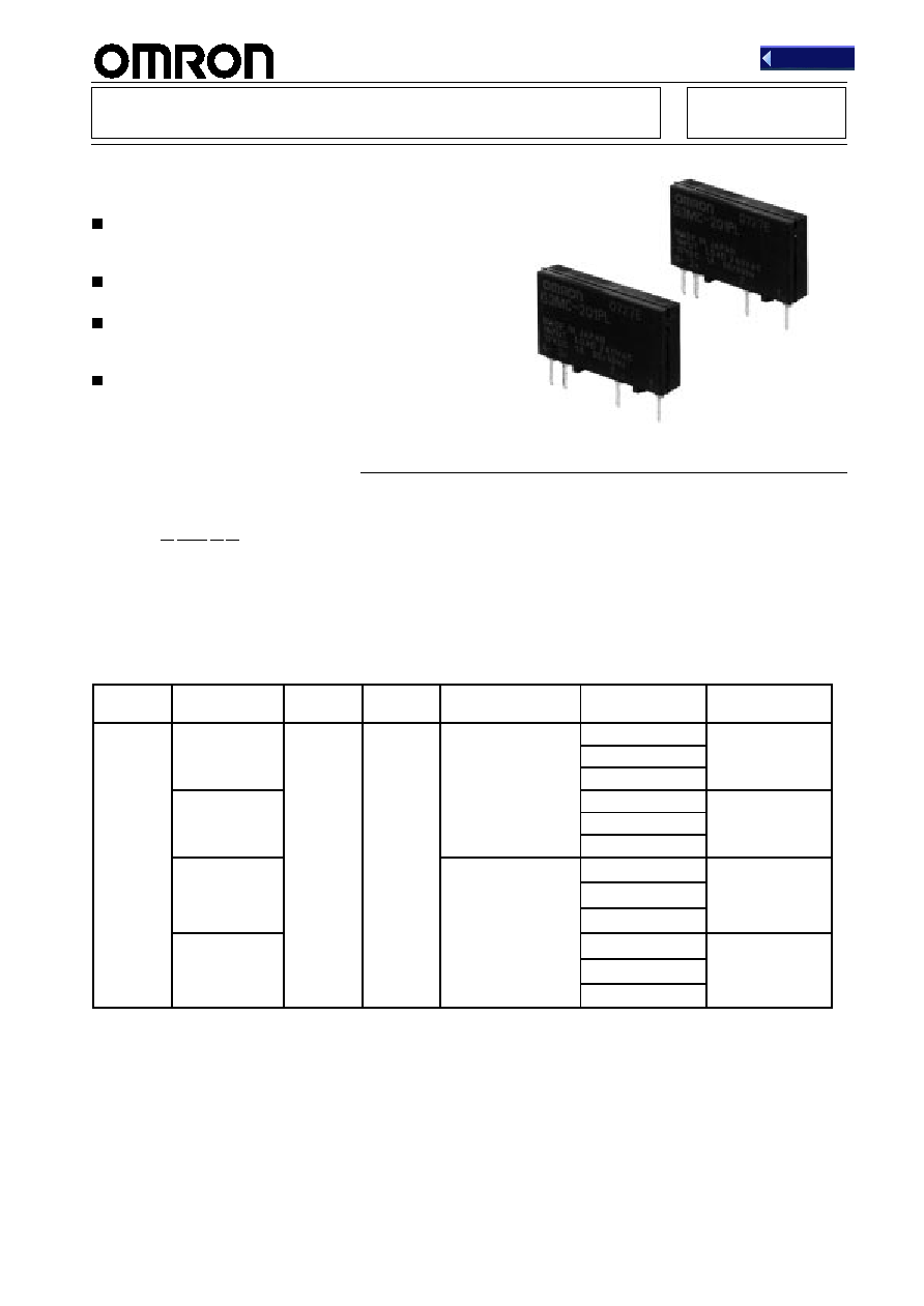
G3MC
Compact, Thin-profile, Low-cost SSR
Switching 1 A (PCB-mounting)
Small bottom surface area (approx. 80% of the
conventional G3MB's) and ideal for close PCB
mounting.
DC input and AC output for an applicable load of 1 A
at 40
∞
C.
Compact, thin-profile SSR of monoblock construc-
tion with an all-in-one frame incorporates a PCB,
terminals, and heat sink.
UL and CSA approvals under application.
Note:
Refer to
Precautions on page 4.
R
CE
Ordering Information
Model Number Legend:
G3MC-
jjjjj
1
2
3
4
1.
Load supply voltage
1:
Max. operating voltage of 100 V min. and 200 V max.
2:
Max. operating voltage of 200 V min. and 300 V max.
2.
Load current
01: 1 A
3.
Terminal
P:
PCB terminal
4.
Zero-cross function
---:
Yes
L:
No
Isolation
Zero-cross
function
Indicator
Snubber
circuit
Applicable output
load
Rated input
voltage
Model
Phototriac
Yes
No
Yes
1 A at 100 to 120 VAC
5 VDC
G3MC-101P
12 VDC
24 VDC
No
5 VDC
G3MC-101PL
12 VDC
24 VDC
Yes
1 A at 100 to 240 VAC
5 VDC
G3MC-201P
12 VDC
24 VDC
No
5 VDC
G3MC-201PL
12 VDC
24 VDC
Note:
UL and CSA approvals for standard SSR models are under application.
Back
G3MC
G3MC
2
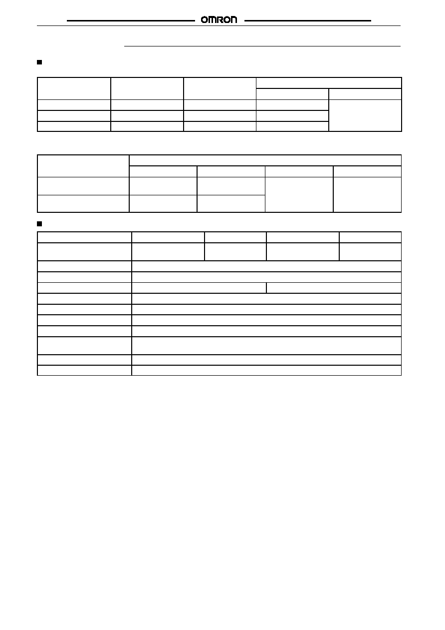
Specifications
Ratings (Ambient Temperature 25
∞
C)
Input
Rated voltage
Operating voltage
Impedance
Voltage levels
Must operate voltage
Must dropout voltage
5 VDC
4 to 6 VDC
300
±
20%
4 VDC max.
1 VDC min.
12 VDC
9.6 to 14.4 VDC
800
±
20%
9.6 VDC max.
24 VDC
19.2 to 28.8 VDC
1.6 k
±
20%
19.2 VDC max.
Note:
All SSR models operate with inputs of 5, 12, or 24 VDC.
Output
Model
Applicable load
Rated load voltage
Load voltage
Load current
Inrush current
G3MC-101P
G3MC-101PL
100 to 120 VAC
50/60 Hz
75 to 132 VAC
50/60 Hz
0.1 to 1 A
8 A (60 Hz, 1 cycle)
G3MC-201P
G3MC-201PL
100 to 240 VAC
50/60 Hz
75 to 264 VAC
50/60 Hz
Characteristics
Item
G3MC-101P
G3MC-101PL
G3MC-201P
G3MC-201PL
Operate time
1 ms + half cycle of load
power supply
1 ms max.
1 ms + half cycle of load
power supply
1 ms max.
Release time
1 ms + half cycle of load power supply
Output ON voltage drop
1.6 V (RMS) max.
Leakage current
1 mA max. (at 100 VAC)
1.5 mA max. (at 200 VAC)
Insulation resistance
1,000 M
min. (at 500 VDC)
Dielectric strength
2,500 VAC, 50/60 Hz for 1 min
Vibration resistance
Malfunction: 10 to 55 Hz, 0.75-mm double amplitude
Shock resistance
Malfunction: 1,000 m/s
2
(approx. 100G)
Ambient temperature
Operating: ≠30
∞
C to 80
∞
C (with no icing)
Storage:
≠30
∞
C to 100
∞
C (with no icing)
Ambient humidity
Operating: 45% to 85%
Weight
Approx. 2.5 g

G3MC
G3MC
3
Engineering Data
Load current (A)
Ambient temperature (
∞
C)
Load Current vs. Ambient
Temperature Characteristics
Inrush Current Resistivity
Non-repetitive (Keep the inrush current to
half the rated value if it occurs repeatedly.)
Inrush current (A. Peak)
Energizing time (ms)
Engineering Data
Note:
All units are in millimeters unless otherwise indicated.
G3MC-101P
G3MC-101PL
G3MC-201P
G3MC-201PL
13.5 max.
24.5 max.
4.5 max.
PCB Dimensions
(Bottom View)
Four, 1.0-dia. holes
Terminal Arrangement
(Bottom View)

G3MC
G3MC
4
Precautions
General Precautions
Be sure to turn off power to the SSR before wiring the SSR, other-
wise an electric shock may be received.
Do not touch the terminals of the SSR while power is being supplied
to the SSR. The terminals are charged with the power, and an elec-
tric shock may be received by touching the terminals.
The built-in capacitor may have a residual voltage after the SSR is
turned off. Be sure to discharge the residual voltage before touching
the terminals of the SSR, otherwise an electric shock may be re-
ceived.
Mounting
1.
Make sure that no excessive voltage or current is imposed on
or flows to the input or output circuit of the SSR, otherwise the
SSR may malfunction or burn.
2.
Solder the terminals of the SSR properly under the required
soldering conditions. The SSR may be abnormally heated
and burn if power is supplied to the terminals soldered
incorrectly.
3.
Do not short-circuit the load of the SSR while power is
supplied to the SSR. Do not short-circuit the power supply
through the SSR. The SSR may be damaged, malfunction, or
burn if the load or power supply is short-circuited.
Correct Use
The terminals of the SSR are highly heat-conductive. Each terminal
must be soldered within 10 s at 260
∞
C or within 5 s at 350
∞
C.
The SSR is of a thin-profile construction. To maintain the vibration
resistance of the SSR, make sure that the space between the SSR
and PCB is 0.1 mm maximum. Lifting of the PCB can be prevented
by setting the hole diameter of the PCBs on both sides slightly
smaller than the actual terminal dimension.
Select the model without the zero-cross function when using the
Unit for phase control output.
The casing works as a heat sink. When mounting two or more Units
closely, make sure that the Units are properly ventilated by taking
ambient temperature rises into consideration. If Units are closely
mounted and used in places with no ventilation, the load current of
each Unit must be 1/2 of the rated load current.
The load terminals are internally connected to a snubber circuit that
absorbs noise. However, if wiring from these terminals is laid with or
placed in the same duct as high-voltage or power lines, noise may
be induced, causing the SSR to operate irregularly or malfunction.
The SSR does not incorporate a circuit protecting the input circuit
from damage resulting from the wrong input polarity. Make sure that
the polarity of the input is correct.
If a surge voltage peaking at more than 250 V is imposed on the
G3MC-102PL or that peaking at more than 450 V is imposed on the
G3MC-202P(L), connect a varistor as a surge absorber in parallel to
the terminals of the load as shown in the following illustration.
SSR
Load
Input
Load