Document Outline
- Front Page
- Ordering Information
- Specifications
- Dimensions
- Precautions
- Contacting Omron

Isolation
Zero cross
Indicator
Rated output load
Rated input voltage
Part number
function
(Applicable output load)
Phototriac
Yes
Yes
5 A at 24 to 240 VAC*
5 to 24 VDC
G3NA-205B
Photocoupler
(19 to 264 VAC)
100 to 120 VAC
200 to 240 VAC
10 A at 24 to 240 VAC*
5 to 24 VDC
G3NA-210B
(19 to 264 VAC)
100 to 120 VAC
200 to 240 VAC
Photocoupler
Yes
Yes
10 A at 200 to 480 VAC*
5 to 24 VDC
G3NA-410B
(180 to 528 VAC)
100 to 240 VAC
--
10 A at 5 to 200 VDC*
5 to 24 VDC
G3NA-D210B
(4 to 220 VDC)
100 to 240 VAC
Phototriac
Yes
20 A at 24 to 240 VAC*
5 to 24 VDC
G3NA-220B
(19 to 264 VAC)
100 to 120 VAC
200 to 240 VAC
Photocoupler
Yes
Yes
20 A at 200 to 480 VAC*
5 to 24 VDC
G3NA-420B
(180 to 528 VAC)
100 to 240 VAC
Photocoupler
Yes
Yes
25 A at 24 to 240 VAC*
5 to 24 VDC
G3NA-225B
(19 to 264 VAC)
100 to 120 VAC
200 to 240 VAC
25 A at 200 to 480 VAC*
5 to 24 VDC
G3NA-425B
(180 to 528 VAC)
100 to 240 VAC
Phototriac
Yes
Yes
40 A at 24 to 240 VAC*
5 to 24 VDC
G3NA-240B
(19 to 264 VAC)
100 to 120 VAC
200 to 240 VAC
Photocoupler
Yes
Yes
40 A at 200 to 480 VAC*
5 to 24 VDC
G3NA-440B
(180 to 528 VAC)
100 to 240 VAC
A Wide Range of Models with 5- to 40-A
Output Currents and Up to
480-VAC/200-VDC Output Voltages
s
All models feature the same compact dimensions
to provide a uniform mounting pitch
s
Built-in MOV effectively absorbs external surges
s
Operation indicator (red LED) enables monitoring
operation
s
Protective cover for greater safety
s
Standard models approved by UL/CSA
s
AC and DC input versions available
Solid State Relay
G3NA
Ordering Information
* Loss time increases under 75 VAC.
NOTE:
When ordering a T�V-approved model, add "-UTU" to the model number as shown below:
Example: G3NA-210B-
UTU
To Order: Select the part number and add the desired rated input voltage, (e.g., G3NA-240B-
100 to 120 VAC).

2
G3NA
G3NA
s
INPUT RATINGS
Specifications
Types
Applicable solid-state relays
Part number
Standard mount
G3NA-205B, G3NA-210B, G3NA-D210B, G3NA-220B, G3NA-410B, G3NA-420B
Y92B-A100
G3NA-225B, G3NA-240B, G3NA-425B, G3NA-440B
Y92B-A150N
G3NA-440B
Y92B-A250
Track mount
G3NA-205B, G3NA-210B, G3NA-D210B, G3NA-410B
Y92B-N50
G3NA-220B, G3NA-420B
Y92B-N100
G3NA-225B, G3NA-240B, G3NA-425B, G3NA-440B
Y92B-N150
s
ACCESSORIES
Heat Sinks
Description
Part number
Mounting bracket for G3NA-240B. Changes pitch to 56 mm (2.21 in.) from 47.5 mm (1.73 in.),
R99-11
the same pitch as G3N-240B.
DIN Rail Track, 50 cm (1.64 feet) length; use with Y92B-N
s s s
s s s
heat sinks
PFP-50M
DIN Rail Track, 1 m (3.28 feet) length; use with Y92B-N
s s s
s s s
heat sinks
PFP-100M
Spacer
PFP-S
End cap
PFP-M
Mounting Track and Accessories
s
OUTPUT RATINGS
*When the appropriate size OMRON heat sink is used.
Note:
1. The input impedance is measured at the maximum value of the rated supply voltage (for example, with the model rated at
100 to 120 VAC, the input impedance is measured at 120 VAC).
2. With constant current input circuit system.
3. Refer to the "Characteristic Data" for further details.
Applicable load
Rated
Load
Load current
Type
load voltage
voltage range
With heat sink*
Without heat sink
Surge current
G3NA-205B
24 to 240 VAC
19 to 264 VAC
0.1 to 5 A
0.1 to 3 A
60 A (60 Hz, 1 cycle)
G3NA-210B
24 to 240 VAC
19 to 264 VAC
0.1 to 10 A
0.1 to 4 A
150 A (60 Hz, 1 cycle)
G3NA-410B
200 to 480 VAC
180 to 528 VAC
0.2 to 10 A
0.2 to 4 A
150 A (60 Hz, 1 cycle)
G3NA-220B
24 to 240 VAC
19 to 264 VAC
0.1 to 20 A
0.1 to 4 A
220 A (60 Hz, 1 cycle)
G3NA-420B
200 to 480 VAC
180 to 528 VAC
0.2 to 20 A
0.2 to 4 A
220 A (60 Hz, 1 cycle)
G3NA-225B
24 to 240 VAC
19 to 264 VAC
0.1 to 25 A
0.1 to 4 A
220 A (60 Hz, 1 cycle)
G3NA-425B
200 to 480 VAC
180 to 528 VAC
0.1 to 25 A
0.1 to 4 A
220 A (60 Hz, 1 cycle)
G3NA-240B
24 to 240 VAC
19 to 264 VAC
0.1 to 40 A
0.1 to 6 A
440 A (60 Hz, 1 cycle)
G3NA-440B
200 to 480 VAC
180 to 528 VAC
0.2 to 40 A
0.2 to 6 A
440 A (60 Hz, 1 cycle)
G3NA-D210B
5 to 200 VDC
4 to 220 VDC
0.1 to 10 A
0.1 to 4 A
20 A (10 ms)
Rated
Operating
Voltage Level
Type
voltage
voltage range
Impedance
Must operate voltage
Must release voltage
G3NA-2
s s
s s
B
5 to 24 VDC
4 to 32 VDC
7 mA max.
(see note 2)
4 VDC max.
1 VDC min.
100 to 120 VAC
75 to 132 VAC
36 k
�
20%
75 VAC, max.
(see note 3)
20 VAC min.
(see note 3)
200 to 240 VAC
150 to 264 VAC
72 k
�
20%
150 VAC max.
(see note 3)
40 VAC min.
(see note 3)
G3NA-4
s s
s s
B
5 to 24 VDC
4 to 32 VDC
5 mA max.
(see note 2)
4 VDC max.
1 VDC min.
100 to 240 VAC
75 to 132 VAC
72 k
�
20%
75 VAC max.
20 VAC min.
G3NA-D210B
5 to 24 VDC
4 to 32 VDC
5 mA max.
(see note 2)
4 VDC max.
1 VDC min.
100 to 240 VAC
75 to 132 VAC
72 k
�
20%
75 VAC max.
20 VAC min.
(Ambient temperature: 25
�
C [77
�
F])

3
G3NA
G3NA
Note: Data shown are of initial value.
G3NA-205B, -210B,
G3NA-410B, -420B,
Type
-220B, -225B
G3NA-240B
-425B, -440B
G3NA-D210B
Operate time
DC input
1/2 of load power source cycle + 1 ms max.
1 ms max.
AC input
1 1/2 of load power source cycle + 1 ms max.
30 ms max.
Release time
DC input
1/2 of load power source cycle + 1 ms max.
5 ms max.
AC input
1 1/2 of load power source cycle + 1 ms max.
30 ms max.
Output ON voltage drop
1.6 V (RMS) max.
1.6 V (RMS) max.
1.8 V (RMS max.)
1.5 V max.
Leakage current
5 mA max. at 100 VAC
10 mA max.
5 mA max.
at 200 VAC
at 200 VDC
10 mA max. at 200 VAC
20 mA max. at 400 VAC
Insulation resistance
100 M
min at 500 VDC
Dielectric strength
2,500 VAC, 50/60 Hz for 1 minute
Vibration
Malfunction
10 to 55 Hz, 1.5 mm double amplitude
Shock
Malfunction
1,000 m/s
2
(approx. 100G)
Ambient temperature
Operating
-30
�
to 80
�
C (-22
�
to 176
�
F) with no icing
Storage
-30
�
to 100
�
C (-22
�
to 212
�
F) with no icing
Humidity
45% to 85% RH
Weight
Approx. 60 g (2.1 oz.)
Approx. 70 g (2.5 oz.)
Approx. 80 g (2.8 oz.)
Approx. 70 g (2.5 oz.)
s
CHARACTERISTICS
s
CHARACTERISTIC DATA
G3NA-225B
G3NA-425B
G3NA-240B
G3NA-440B
Ambient temperature (
�
C)
Ambient temperature (
�
C)
Ambient temperature (
�
C)
Load current (A)
Load current (A)
Ambient temperature (
�
C)
Load current (A)
Ambient temperature (
�
C)
Load current (A)
Load current (A)
Load current (A)
Ambient temperature (
�
C)
Load Current vs. Ambient Temperature Characteristics
G3NA-210B
G3NA-220B
G3NA-205B
G3NA-410B
G3NA-420B

4
G3NA
G3NA
Surge Current Resistivity
G3NA-210B
G3NA-220B, G3NA-225B,
G3NA-205B
G3NA-410B
G3NA-420B, G3NA-425B
Energizing time (ms)
Ambient temperature (
�
C)
Load current (A)
Energizing time (ms)
Inr
ush current (A), peak
Inr
ush current (A), peak
Inr
ush current (A), peak
Energizing time (ms)
s
CHARACTERISTIC DATA (continued)
Load Current vs. Ambient Temperature Characteristics
G3NA-D210B
G3NA-240B
G3NA-440B
G3NA-D210B
Energizing time (ms)
Inr
ush current (A), peak
Inr
ush current (A), peak
Energizing time (ms)

5
G3NA
G3NA
Heat Sink Size vs. Load Current
G3NA-220B
Load current (A)
Heat sink siz
e (cm
2
)
Note:
The heat sink size refers to the combined area of the sides of the heat sink that radiate heat. For example, when a current of
18 A is allowed to flow through the SSR at 40
�
C, the graph shows that the heat sink size is about 450 cm
2
. Therefore, if the
heat sink is square, one side of the heat sink must be 15 cm (15
2
x 2 = 450) or longer.
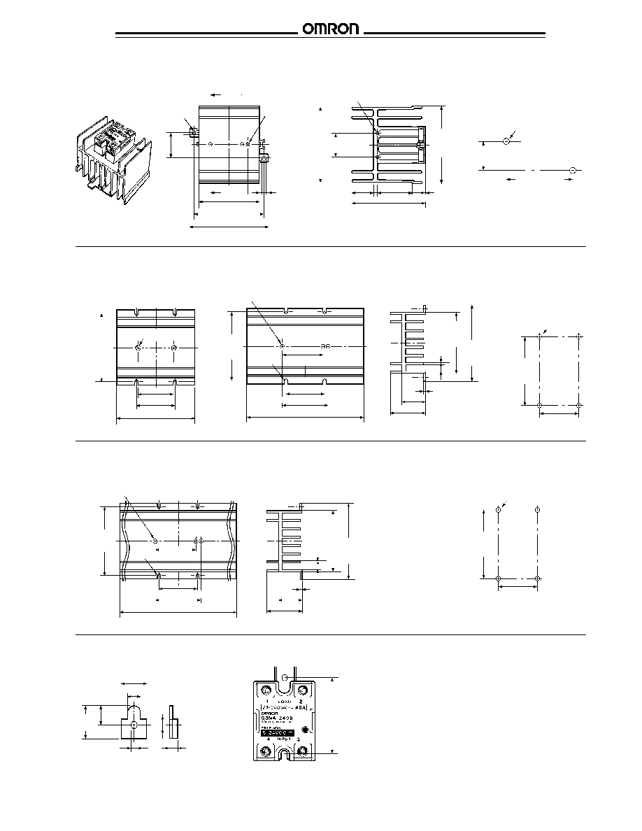
G3NA-205B, G3NA-210B, G3NA-220B,
G3NA-225B, G3NA-410B,
G3NA-420B, G3NA-425B
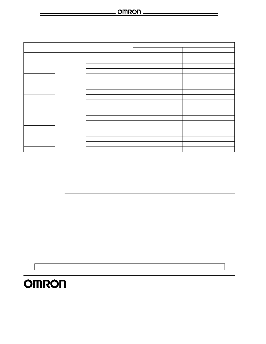
Terminal arrangement/
Mounting holes
Internal connections
(Bottom view)
(Top view)
s
SOLID-STATE RELAYS
Unit: mm (inch)
Dimensions
Four -
M4 x 10 (0.39)
58
(2.28)
max.
47.5
(1.87)
44
(1.73)
Operation
indicator
4.5 (0.18) dia.
43 (1.69) max.
25 (0.98)
4.5 (0.18)
13.8 (0.54)
25 (0.98) max.
27 (1.06) max.
Load
Load
Input
1
(-)
4
2
(+)
3
Load
power
supply
Two,
4.4 (0.17) dia. or M4
47.6
�
0.2
(1.87
�
0.01)
G3NA-240B, G3NA-440B
Terminal arrangement/
Mounting holes
Internal connections
(Bottom view)
(Top view)
4.5 (0.18) dia.
47.5
(1.87)
44
(1.73)
58
(2.28)
min.
Two,
M4 x 10
(0.39)
Operation
indicator
Two,
M5 x 12 (0.47)
13.8 (0.54)
27 (1.06) max.
25 (0.98)
4.5 (0.18)
43 (1.69) max.
25 (0.98) max.
Load
Load
Input
1
(-)
4
2
(+)
3
Load
power
supply
Two,
4.4 (0.17) dia. or M4
47.6
�
0.2
(1.87
�
0.01)
In the case of surface mounting, a 30% derating of load current is required.

6
G3NA
G3NA
Track Mount Heat Sink � Y92B-N50
Mounting holes
(Top view)
G3NA-D210B
Terminal arrangement/
Mounting holes
Internal connections
(Bottom view)
(Top view)
s
SOLID-STATE RELAYS (continued)
Unit: mm (inch)
4.5 (0.18) dia.
Operation
indicator
Four,
M4 x 10 (0.39)
47.5
(1.87)
44
(1.73)
4.5 (0.18)
13.8 (0.54)
58
(2.28)
max.
25 (0.98) max.
27 (1.06) max.
43 (1.69) max.
25 (0.98)
Load
Input
Load
power
supply
1
-
(-)
4
Load
2
+
(+)
3
47.6
�
0.2
(1.87
�
0.01)
Two,
4.4 (0.17) dia. or M4
s
HEAT SINKS
4.6 (0.18) dia.
35
(1.38)
30.5
�
0.3
(1.20
�
0.01)
90
�
0.3 (3.54
�
0.01)
47.6 (1.87)
77 (3.03) max.
100 (3.94) max.
5.6
(0.22)
Two, M4 holes
Two, M3 holes
Two, 3.2 (0.13) dia. holes
44
(1.73)
max.
30
(1.18)
47
(1.85)
max.
4.5 (0.18)
51 (2.01) max.
6 (0.24)
5
(0.20)
90
�
0.4
(3.54
�
0.02)
Two, 4.4 (0.17) dia.
or M4 holes
35
�
0.2
(1.38
�
0.01)
Weight: approx. 200 g (7 oz.)
Track Mount Heat Sink � Y92B-N100
Mounting holes
(Top view)
Two, 3.2 (0.13) dia. holes
71
(2.80)
max.
28
(1.10)
74
(2.91)
max.
4.5 (0.18)
100 (3.94) max.
5 (0.20)
Two, M3 holes
35
(1.38)
90
�
0.3 (3.54
�
0.01)
100 (3.94) max.
77 (3.03) max.
47.6 (1.87)
5.6
(0.22)
Two, M4 holes
4.6 (0.18) dia.
30.5
�
0.3
(1.20
�
0.01)
13 (0.51)
30 (1.18)
90
�
0.4
(3.54
�
0.02)
Two, 4.4 (0.17) dia.
or M4 holes
35
�
0.2
(1.38
�
0.01)
Weight: approx. 400 g (14 oz.)
7
G3NA
G3NA
Weight: approx. 560 g (20 oz.)
Track Mount Heat Sink � Y92B-N150
Mounting holes
(Top view)
35
(1.38)
47.6
(1.87)
Two,
M4 holes
4.6 (0.18) dia.
56
�
0.3
(2.21
�
0.01)
77 (3.03) max.
5.6
(0.22)
30 (1.18)
100
(3.94)
max.
104
(4.09)
max.
28
(1.10)
4.5 (0.18)
Two, 3.2 (0.13) dia. holes
100 (3.94) max.
13 (0.51)
5 (0.20)
100 (3.94) max.
90
�
0.3 (3.54
�
0.01)
90
�
0.4
(3.54
�
0.02)
Two, 4.4 (0.17) dia.
or M4 holes
35
�
0.2
(1.38
�
0.01)
Standard Mount Heat Sinks
Y92B-A100
Y92B-A150
Mounting holes
Y92B-A100, Y92B-A150N
Y92B-A250
4.6 (0.18)
21
(0.83)
12.5
(0.49)
5
(0.20)
8 (0.32)
56
(2.21)
Note:
Use mounting bracket R99-11 to mount the
G3NA-240B with a pitch of 56 mm (2.21 in)
instead of 47.5 mm (1.87 in) to match the pitch
of G3N-240B.
16 (0.63)
4 (0.16)
90
�
0.1
(3.54
�
0.004)
50
�
0.1
(1.97
�
0.004)
Four, 4.4 (0.17) dia.
or M4 holes
Two, M4 holes
47.6 (1.87)
50
�
0.1 (1.97
�
0.004)
100 (3.93) max.
90
�
0.1
(3.54
�
0.004)
90
�
0.1
(3.54
�
0.004)
50
�
0.1 (1.97
�
0.004)
56
�
0.5 (2.21
�
0.02)
R2.2
(0.09)
150 (5.91) max.
47.6 (1.87)
Three, M4 holes
Standard Mount Heat Sinks
Y92B-A250
Mounting holes
90
�
0.1
(3.54
�
0.004)
50
�
0.1
(1.97
�
0.004)
Four, 4.4 (0.17) dia.
or M4 holes
Three, M4 holes
90
�
0.1
(3.54
�
0.004)
50
�
0.1 (1.97
�
0.004)
56
�
0.5 (2.21
�
0.02)
R2.2
(0.09)
47.6 (1.87)
2 (0.08)
45.5 (1.79) max.
1.5
(0.06)
9.6 (0.38)
1.5
(0.06)
80.5
(3.17)
max.
100.5
(3.94)
max.
30 (1.18)
250 (9.84) max.
R99-11 Mounting Bracket for G3NA-240B
2 (0.08)
45.5 (1.79) max.
1.5
(0.06)
9.6 (0.38)
1.5
(0.06)
80.5
(3.17)
max.
100.5
(3.94)
max.
30 (1.18)
8
G3NA
G3NA
Contact ratings
SSR type
Input voltage
Load type
Without heat sink
With heat sink
(see note 1)
G3NA-205B
5 to 24 VDC
General use/Tungsten
3 A, 240 VAC
5 A, 240 VAC
100 to 120 VAC
Motor
2.5 FLA, 15 LRA, 240 VAC
2.5 FLA, 15 LRA, 240 VAC
G3NA-210B
200 to 240 VAC
General use/Tungsten
4 A, 240 VAC
10 A, 240 VAC
Motor
2.5 FLA, 15 LRA, 240 VAC
5 FLA, 30 LRA, 240 VAC
G3NA-220B
General use/Tungsten
4 A, 240 VAC
20 A, 240 VAC
Motor
2.5 FLA, 15 LRA, 240 VAC
10 FLA, 60 LRA, 240 VAC
G3NA-225B
General use/Tungsten
4 A, 240 VAC
25 A, 240 VAC
Motor
2.5 FLA, 15 LRA, 240 VAC
12 FLA, 72 LRA, 240 VAC
G3NA-240B
General use/Tungsten
6 A, 240 VAC
40 A, 240 VAC
Motor
5 FLA, 30 LRA, 240 VAC
20 FLA, 120 LRA, 240 VAC
G3NA-410B
5 to 24 VDC
General use/Tungsten
4 A, 480 VAC
10 A, 480 VAC
100 to 240 VAC
Motor
2.5 FLA, 15 LRA, 480 VAC
5 FLA, 30 LRA, 480 VAC
G3NA-420B
General use/Tungsten
4 A, 480 VAC
20 A, 480 VAC
Motor
2.5 FLA, 15 LRA, 480 VAC
10 FLA, 60 LRA, 480 VAC
G3NA-425B
General use/Tungsten
4 A, 480 VAC
25 A, 480 VAC
Motor
2.5 FLA, 15 LRA, 480 VAC
12 FLA, 72 LRA, 480 VAC
G3NA-440B
General use/Tungsten
6 A, 480 VAC
40 A, 480 VAC
Motor
5 FLA, 30 LRA, 480 VAC
20 FLA, 120 LRA, 480 VAC
G3NA-D210B
General use
4 A, 200 VDC
10 A, 200 VDC
s
APPROVALS
UL (File No. E64562)/CSA (File No. LR35535)
Note:
1. When used with the proper OMRON heat sink part number or an appropriately dimensioned equivalent.
2. The rated values approved by each of the safety standards (e.g., UL, CSA, and TUV) may be different from the performance
characteristics individually defined in this catalog.
3. In the interest of product improvement, specifications are subject to change.
Precautions
See General Information Section near the front of this catalog for Solid State Precautions.
OMRON ELECTRONICS, INC.
OMRON CANADA, INC.
One East Commerce Drive
885 Milner Avenue
Schaumburg, IL 60173
Scarborough, Ontario M1B 5V8
1-800-55-OMRON
416-286-6465
Cat. No. GC RLY7
01/00
Specifications subject to change without notice.
Printed in the U.S.A.
NOTE: DIMENSIONS ARE SHOWN IN MILLIMETERS. To convert millimeters to inches divide by 25.4.