157
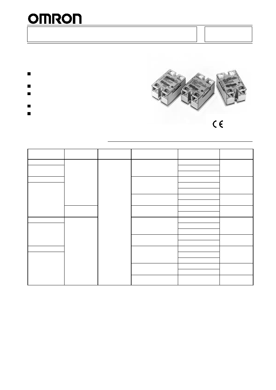
Solid-state Relay
G3NA
A Wide Range of Models with 5- to 40-A
Output Currents and Up to
480-VAC/200-VDC Output Voltages
All models feature the same compact dimensions
to provide a uniform mounting pitch.
Built-in varistor effectively absorb external surges.
Operation indicator (red LED) enables monitoring
operation.
Protective cover for greater safety.
Standard models approved by UL/CSA and -UTU
models by VDE (TÐV).
RCE
Ordering Information
Isolation
Zero cross
function
Indicator
Rated output load
(Applicable output load)
Rated input voltage
Model
Phototriac
Yes
Yes
5 A at 24 to 240 VAC*
(19 t 264 VAC)
5 to 24 VDC
G3NA-205B
Photocoupler
5
a
o
0
C
(19 to 264 VAC)
100 to 120 VAC
Photocou ler
200 to 240 VAC
Phototriac
10 A at 24 to 240 VAC*
(19 t 264 VAC)
5 to 24 VDC
G3NA-210B
Photocoupler
0
a
o
0
C
(19 to 264 VAC)
100 to 120 VAC
o ocou e
200 to 240 VAC
10 A at 200 to 480 VAC*
(180 t 528 VAC)
5 to 24 VDC
G3NA-410B
0
a
00 o 80
C
(180 to 528 VAC)
100 to 240 VAC
---
10 A at 5 to 200 VDC
(4 t 220 VDC)
5 to 24 VDC
G3NA-D210B
0
a 5 o 00
C
(4 to 220 VDC)
100 to 240 VAC
Phototriac
Yes
20 A at 24 to 240 VAC*
(19 t 264 VAC)
5 to 24 VDC
G3NA-220B
Photocoupler
0
a
o
0
C
(19 to 264 VAC)
100 to 120 VAC
o ocou e
200 to 240 VAC
20 A at 200 to 480 VAC*
(180 t 528 VAC)
5 to 24 VDC
G3NA-420B
0
a
00 o 80
C
(180 to 528 VAC)
100 to 240 VAC
Phototriac
40 A at 24 to 240 VAC*
(19 t 264 VAC)
5 to 24 VDC
G3NA-240B
Photocoupler
0
a
o
0
C
(19 to 264 VAC)
100 to 120 VAC
o ocou e
200 to 240 VAC
40 A at 200 to 480 VAC*
(180 t 528 VAC)
5 to 24 VDC
G3NA-440B
0
a
00 o 80
C
(180 to 528 VAC)
100 to 240 VAC
50 A at 200 to 480 VAC*
(180 to 528 VAC)
5 to 24 VDC
G3NA-450B
*Loss time increases under 75 VAC. (Refer to page 164.)
Note:
When ordering a TÐV-approved model, add "-UTU" to the model number as shown below:
Example: G3NA-210B-UTU
G3NA
G3NA
158
Accessories (Order Separately)
Heat Sink
The following heat sinks are thin and can be DIN-track mounted
(except Y92B-P250).
See
Dimensions for details.
Model
Applicable SSR
Y92B-N50
G3NA-205B, G3NA-210B, G3NA-D210B,
G3NA-410B, G3NE-205T(L), G3NE-210T(L)
Y92B-N100
G3NA-220B, G3NA-420B, G3NE-220T(L)
Y92B-N150
G3NA-240B, G3NA-440B
Y92B-P250
G3NA-450B
Low-cost Models
Model
Applicable SSR
Y92B-A100
G3NA-205B, G3NA-210B, G3NA-D210B,
G3NA-220B, G3NA-410B, G3NA-420B
Y92B-A150N
G3NA-240B, G3NA-440B
Y92B-A250
G3NA-440B
Mounting Bracket
Used to mount the G3NA with a mounting dimension of 56 mm.
Model
Applicable SSR
R99-11
G3NA-240B, G3NA-440B
See
Dimensions for details. (Refer to page 164.)
Specifications
Ratings
Input (Ambient Temperature: 25
∞
C)
Model
Rated voltage
Operating voltage
Impedance
Voltage level
Must operate
voltage
Must release
voltage
G3NA-2
jj
B
5 to 24 VDC
4 to 32 VDC
7 mA max.*
4 VDC max.
1 VDC min.
100 to 120 VAC
75 to 132 VAC
36 k
±
20%
75 VAC max.**
20 VAC min.**
200 to 240 VAC
150 to 264 VAC
72 k
±
20%
150 VAC max.**
40 VAC min.**
G3NA-4
jj
B
5 to 24 VDC
4 to 32 VDC
5 mA max.*
4 VDC max.
1 VDC min.
G3NA-D210B
100 to 240 VAC
75 to 264 VAC
72 k
±
20%
75 VAC max.
20 VAC min.
Note:
The input impedance is measured at the maximum value of the rated supply voltage (for example, with the model rated at 100 to
120 VAC, the input impedance is measured at 120 VAC).
*With constant current input circuit system. The impedance for the G3NA-
jjj
B-UTU is 15 mA max.
**Refer to the
Engineering Data for further details.
Output
Model
Applicable load
Rated load voltage
Load voltage range
Load current
Inrush current
With heat sink*
Without heat sink
G3NA-205B
24 to 240 VAC
19 to 264 VAC
0.1 to 5 A
0.1 to 3 A
60 A (60 Hz, 1 cycle)
G3NA-210B
0.1 to 10 A
0.1 to 4 A
150 A (60 Hz, 1 cycle)
G3NA-410B
200 to 480 VAC
180 to 528 VAC
0.2 to 10 A
0.2 to 4 A
G3NA-220B
24 to 240 VAC
19 to 264 VAC
0.1 to 20 A
0.1 to 4 A
220 A (60 Hz, 1 cycle)
G3NA-420B
200 to 480 VAC
180 to 528 VAC
0.2 to 20 A
0.2 to 4 A
G3NA-240B
24 to 240 VAC
19 to 264 VAC
0.1 to 40 A
0.1 to 6 A
440 A (60 Hz, 1 cycle)
G3NA-440B
200 to 480 VAC
180 to 528 VAC
0.2 to 40 A
0.2 to 6 A
G3NA-450B
200 to 480 VAC
180 to 528 VAC
0.2 to 50 A
0.2 to 6 A
G3NA-D210B
5 to 200 VDC
4 to 220 VDC
0.1 to 10 A
0.1 to 4 A
20 A (10 ms)
*When OMRON's heat sink (refer to the accessories) or a heat sink of specified size is used.
G3NA
G3NA
159
Characteristics
Item
G3NA-205B, -210B,
-220B
G3NA-240B
G3NA-410B, -420B,
-440B, -450B
G3NA-D210B
Operate time
1/2 of load power source cycle + 1 ms max. (DC input)
3/2 of load power source cycle + 1 ms max. (AC input)
1 ms max. (DC input)
30 ms max. (AC input)
Release time
1/2 of load power source cycle + 1 ms max. (DC input)
3/2 of load power source cycle + 1 ms max. (AC input)
5 ms max. (DC input)
30 ms max. (AC input)
Output ON voltage drop
1.6 V (RMS) max.
1.8 V (RMS) max.
1.5 V max.
Leakage current
5 mA max. (at 100 VAC)
10 mA max. (at 200 VAC)
10 mA max. (at 200 VAC)
20 mA max. (at 400 VAC)
5 mA max. (at 200 VDC)
Insulation resistance
100 M
min. (at 500 VDC)
Dielectric strength
2,500 VAC, 50/60 Hz for 1 min
Vibration resistance
Malfunction: 10 to 55 Hz, 1.5-mm double amplitude
Shock resistance
Malfunction: 1,000 m/s
2
Ambient temperature
Operating: ≠30
∞
C to 80
∞
C (with no icing or condensation)
Storage:
≠30
∞
C to 100
∞
C (with no icing or condensation)
Approved standards
UL508 File No. E64562/CSA C22.2 (No.0, No.14) File No. LR35535 (except for G3NA-450B)
TÐV R9151660 (EN60950) (except for G3NA-4
j
0B)
Ambient humidity
Operating: 45% to 85%
Weight
Approx. 60 g
Approx. 70 g
Approx. 80 g
Approx. 70 g
G3NA
G3NA
160
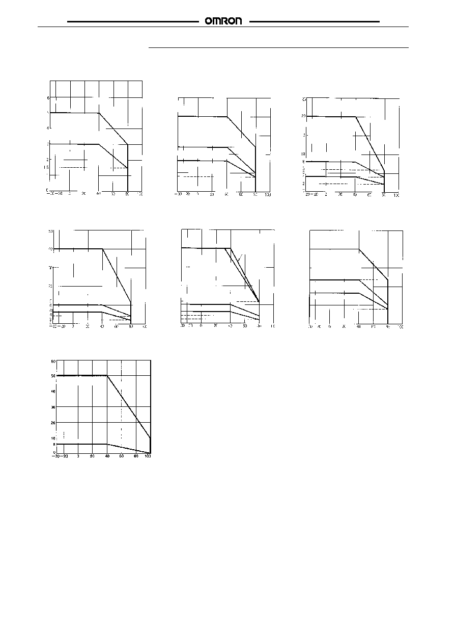
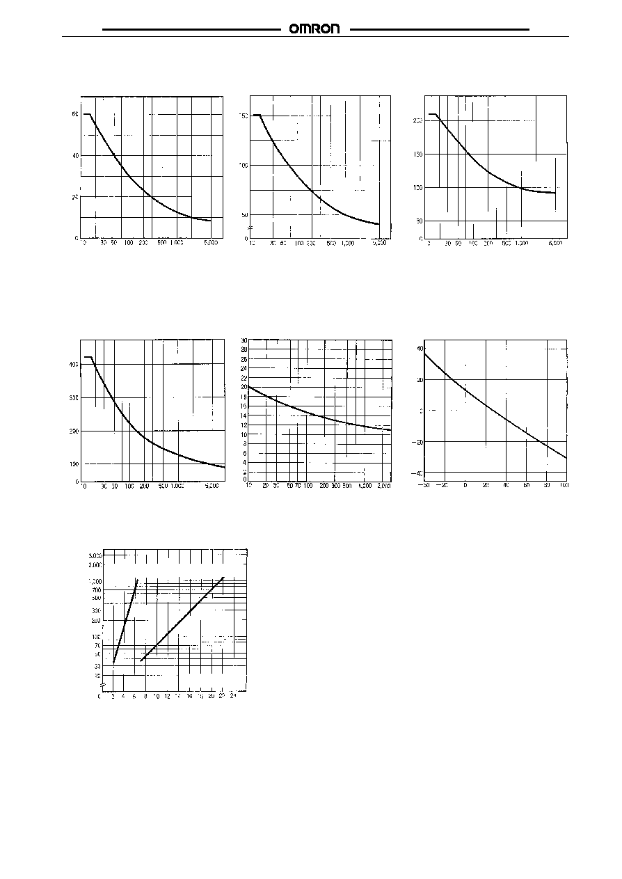
Engineering Data
Load Current vs. Ambient Temperature Characteristics
G3NA-205B
G3NA-210B/410B
G3NA-220B/420B
Ambient temperature (
∞
C)
Ambient temperature (
∞
C)
Ambient temperature (
∞
C)
Load current (A)
Load current (A)
Load current (A)
20
16
10
8
6
5
4
2
0
With standard heat sink
(Y92B-A100 or Y92B-
N50) or aluminum plate
measuring 75 mm x 75
mm x 13.2 mm
(W x H x D)
Without heat sink
With standard heat sink
(Y92B-A100 or Y92B-N50)
or aluminum plate measur-
ing 150 mm x 150 mm x
13.2 mm
(W x H x D)
With iron plate measuring
100 x 100 x 0.8 (W x H x D)
Without heat sink
With standard heat
sink (Y92B-A100 or
Y92B-N100) or alumi-
num plate measuring
200 mm x 200 mm x
13.2 mm (W x H x D)
With iron plate measuring
100 x 100 x 0.8 (W x H x D)
Without heat sink
G3NA-240B
G3NA-440B
G3NA-D210B
Load current (A)
Ambient temperature (
∞
C)
Load current (A)
Ambient temperature (
∞
C)
Load current (A)
Ambient temperature (
∞
C)
50
45
40
30
20
12
10
6
4
2
0
20
10
6
5
4
2
0
With standard heat
sink (Y92B-A150N
or Y92B-N150)
With iron plate measuring
100 x 100 x 0.8 (W x H x D)
Without heat sink
With Y92B-
A250 or heat
sink with a ra-
diation efficien-
cy of 1
∞
C/W.
With standard heat
sink (Y92B-A150N or
Y92B-N150)
With iron plate measuring
100 x 100 x 0.8 (W x H x D)
Without heat sink
With standard heat sink
(Y92B-A100 or Y92B-N50)
or aluminum plate measur-
ing 150 mm x 150 mm x
13.2 mm (W x H x D)
With iron plate measuring
100 x 100 x 0.8 (W x H x D)
Without heat sink
G3NA-450B
Load current (A)
Ambient temperature (
∞
C)
With standard heat sink
(Y92B-P250)
Without heat sink
G3NA
G3NA
161
Inrush Current Resistivity
Non-repetitive (Keep the inrush current to half the rated value if it occurs repetitively.)
G3NA-205B
G3NA-210B/410B
G3NA-220B/420B
Inrush current (A. Peak)
Energizing time (ms)
Inrush current (A. Peak)
Energizing time (ms)
Inrush current (A. Peak)
Energizing time (ms)
Ambient temperature (
∞
C)
G3NA-240B/440B/450B
G3NA-D210B
Temperature Characteristics
(with Must Operate Voltage
and Must Release Voltage)
G3NA-2
jj
B AC Input
Inrush current (A. Peak)
Energizing time (ms)
Inrush current (A. Peak)
Energizing time (ms)
V
ariation rate (%)
Heat Sink Size vs. Load Current
G3NA-220B
Heat sink size (cm )
2
Ambient temperature
80
∞
C
Ambient temperature
40
∞
C
Aluminum plate
3.2 mm thick
Load current (A)
Note:
The heat sink size refers to the combined area of the sides of the heat
sink that radiate heat. For example, when a current of 18 A is allowed
to flow through the SSR at 40
∞
C, the graph shows that the heat sink
size is about 450 cm
2
. Therefore, if the heat sink is square, one side of
the heat sink must be 15 cm (15
2
x 2 = 450) or longer.
G3NA
G3NA
162
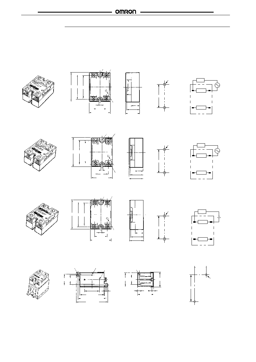
Dimensions
Note:
All units are in millimeters unless otherwise indicated.
In the case of surface mounting, a 30% derating of the load current is required.
The orientation indicated by the external dimensions is not the correct mounting orientation. When opening mounting holes, refer to the mount-
ing hole dimensions.
G3NA-205B, G3NA-210B, G3NA-220B, G3NA-410B, G3NA-420B
13.8
Mounting Holes
Terminal Arrangement/
Internal Connections
(Top View)
47.6
±
0.2
Two, 4.3-dia.
or M4 holes
Load
Input
1
2
3
4
(-)
(+)
Load
power
supply
Load
25 max.
27 max.
4.5 dia.
Four, M4 x 8
screws
4.5
25
43 max.
58 max. 47.5 44
Operating
indicator
Mounting Holes
Terminal Arrangement/
Internal Connections
(Top View)
47.6
±
0.2
Two, 4.3-dia.
or M4 holes
Load
Input
1
2
3
4
(-)
(+)
Load
power
supply
Load
G3NA-240B, G3NA-440B, G3NA-450B
13.8
25 max.
27 max.
58 min.47.5 44
4.5 dia.
Two, M5 x 12 screws
Two,
M 4 x 8
4.5
25
43 max.
Operating
indicator
G3NA-D210B
47.6
±
0.2
Two, 4.3-dia.
or M4 holes
Mounting Holes
Terminal Arrangement/
Internal Connections
(Top View)
Load
Input
1
2
3
4
(-)
(+)
Load
-
+
Load
power
supply
25 max.
27 max.
4.5 dia.
Four,
M4 x 8
screws
4.5
25
43 max.
58 max. 47.5 44
Operating
indicator
13.8
Note:
The load can be connected to either the positive or negative side.
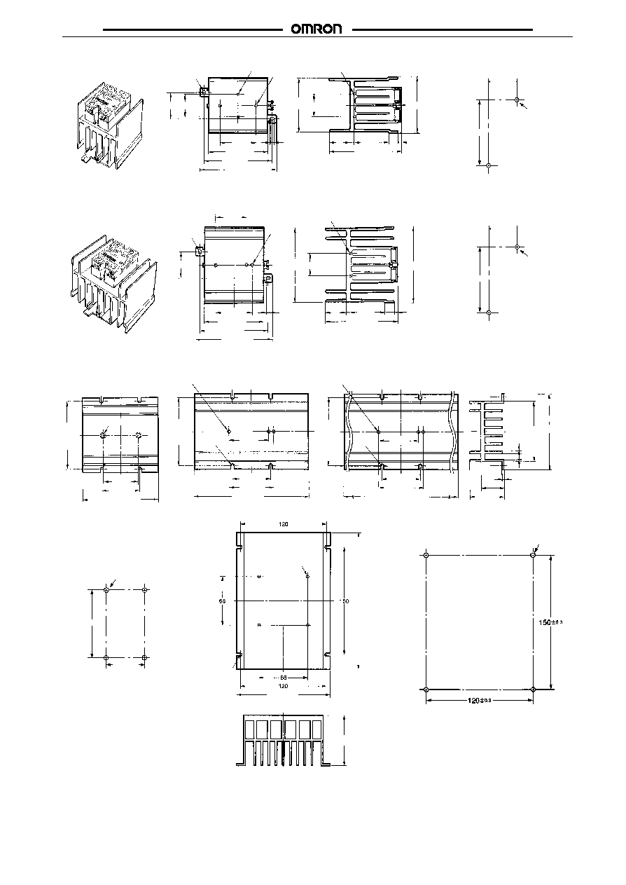
Mounting Holes
Heat Sink
Y92B-N50
4.6 dia.
Two, M3 holes
Two, M4 holes
5.6
47.6
77 max.
90
±
0.3
100 max.
35 30.5
±
0.3
44 max. 30
5
4.5
6
47 max.
Two, 3.2-dia.
holes
35
±
0.2
90
±
0.4
Two, 4.4-dia.
or M4 holes
Weight: approx. 200 g
51 max.
G3NA
G3NA
163
Y92B-N100
4.6 dia.
Two, M3 holes
Two, M4
holes
35 30.5
±
0.3
47.6
77 max.
90
±
0.3
100 max.
5.6
30
71 max.
5
100 max.
4.5
75 max.
Two, 3.2-dia. holes
35
±
0.2
90
±
0.4
Two, 4.4-dia.
or M4 holes
Mounting Holes
Weight: approx. 400 g
28
13
Y92B-N150
4.6 dia.
35
47.6
77 max.
5.6
100 max.
100 max.
5
4.5
30
100 max.
90
±
0.3
Two, 3.2-dia. holes
104 max.
35
±
0.2
90
±
0.4
Two, 4.4-dia.
or M4 holes
Mounting Holes
Weight: approx. 560 g
56
±
0.3
13
28
Three,
M4
holes
Mounting Holes
Y92B-A100
Y92B-A150
Y92B-A250
Y92B-A100
Y92B-A150N
Two, M4 holes
47.6
50
±
0.1
100 max.
Three, M4 holes
47.6
50
±
0.1
56
±
0.5
150 max.
R2.2
Three, M4 holes
R2.2
47.6
50
±
0.1
56
±
0.5
250 max.
100.5 max.
80.5 max.
1.5
9.6
2
1.5
Y92B-A250
90
±
0.1
50
±
0.1
Four, 4.3-dia. or M4 holes
30
45.5 max.
90 0.1
±
90 0.1
±
90 0.1
±
70 max.
Four, M4
Four, R2.5
130.5 max.
190.5 max.
Mounting Holes
Four, 4.5 dia. or M4

G3NA
G3NA
164
R99-11
21
12.5
16
8
4
4.6
5
56
Use Mounting Bracket R99-11 so that the
G3NA-240B can be mounted with the same pitch
as that of the G3N-240B.
Y92B-P250
70 max.
Four, M4
Four, R2.5
130.5 max.
190.5 max.
Mounting Holes
Four, 4.5 dia. or M4
Precautions
Refer to pages 11 to 19 for general precautions.
Load Connection
For an AC load, use a power supply rated at 50 or 60 Hz.
The maximum operating frequency is 10 Hz.
The G3NA has a built-in varistor for overvoltage protection.
Zero Cross Function
An SSR with a zero cross function operates when an AC load volt-
age reaches the zero point or its vicinity. This reduces clicking
noises when the load is input, and minimizes the influence of an in-
ductive load, such as a lamp, heater, or motor, on the power supply
because the inrush current of the load is reduced. This can also
minimize the scale of the inrush current protection circuit.
Output (load voltage)
Input
ON
OFF
At a low applied voltage, such as 24 VAC, the load current is not fully
supplied. When the Unit is switched ON, the voltage required to
power the Unit deprives the output signal of the necessary voltage
level and thus creates loss time. The lower the load voltage is, the
greater the loss time is. This condition, however, will not create any
serious problems.
Loss time
For a DC or L load, a diode should be connected in parallel the load
to absorb the counter electromotive force of the load.
SSR
Input
Load
Load power
supply
G3NA
G3NA
165
When attaching a heat sink to the G3NA, apply Silicone Grease or
equivalent heat conductive grease on the heat sink. (Toshiba Sili-
con, Shinetsu Silicon, etc.)
Tighten the mounting screws of the heat sink with a torque of 0.78 to
0.98 N
S
m.
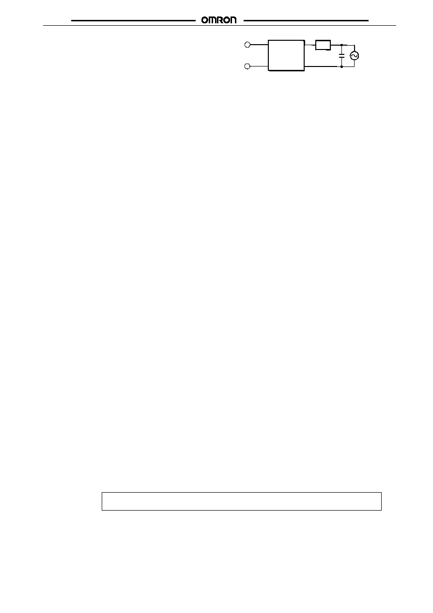
EN55011 Measurement of Mains Terminal Disturbance
Voltage
The G3NA-UTU conforms to EN55011 standards when a capacitor
is connected to the load power supply as shown in the following cir-
cuit diagram.
G3NA-UTU
Output
Load
Input
Recommended Capacitor:
Nissei Denki's MKT-series R40 (1
µ
F)
The output terminal side of the G3NA-D210B is connected to a built-
in diode for protecting the SSR from damage that may result from
reverse connection. The SSR, however, cannot withstand one min-
ute or more if the wires are connected in reverse order. Therefore,
pay the utmost attention not to make polarity mistakes on the load
side.
ALL DIMENSIONS SHOWN ARE IN MILLIMETERS.
To convert millimeters into inches, multiply by 0.03937. To convert grams into ounces, multiply by 0.03527.
Cat. No. K067-E1-1D