Document Outline
- First Page
- Ordering Information
- Specifications
- Engineering Data
- Dimensions
- Precautions
- Contact Omron

Solid State Relay
G3NE
1
Solid State Relay
G3NE
Compact, Low-cost, SSR Switching
5 to 20 A
D
Wide load voltage range: 75 to 264 VAC.
D
Dedicated, compact aluminum PCB and power elements
used.
D
Built-in varistor effectively absorbs external surges.
D
Quick-connect #110 input terminals and #250 output
connections. (#187 input terminals available).
D
Approved by UL, CSA and TÐV; marked with CE.
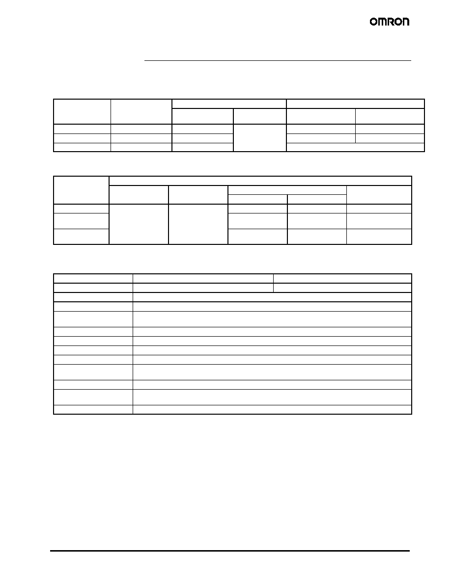
Ordering Information
To order: Select the part number and add the desired coil voltage rating, (e.g., G3NE-205T-US DC24)
Isolation
Zero cross
function
Indicator
Rated output load
(applicable output load)
Rated input voltage
Model
Phototriac
Yes
No
5 A at 100 to 240 VAC
(5 A at 75 to 264 VAC)
5, 12, 24 VDC
G3NE-205T-US
10 A at 100 to 240 VAC
(10 A at 75 to 264 VAC)
G3NE-210T-US
20 A at 100 to 240 VAC
(20 A at 75 to 264 VAC)
G3NE-220T-US
No
5 A at 100 to 240 VAC
(5 A at 75 to 264 VAC)
G3NE-205TL-US
10 A at 100 to 240 VAC
(10 A at 75 to 264 VAC)
G3NE-210TL-US
20 A at 100 to 240 VAC
(20 A at 75 to 264 VAC)
G3NE-220TL-US
Note: For information on ordering #187 input terminals contact your local Omron representative
J
ACCESSORIES (ORDER SEPARATELY)
Heat Sink
The following heat sinks are thin and can be track-mounted.
See Dimensions for details.
Part number
Applicable SSR
Y92B-N50
G3NE-205T(L)/-210T(L)
Y92B-N100
G3NE-220T(L)
2
Solid State Relay
G3NE
Specifications
J
RATINGS
Input
Rated voltage
Operating voltage
Voltage level
Input impedance
Must operate
Must release
With zero cross function Without zero cross
function
5 VDC
4 to 6 VDC
4 VDC max.
1 VDC min.
250 ±20%
300 k ±20%
12 VDC
9.6 to 14.4 VDC
9.6 VDC max.
600 ±20%
800 k ±20%
24 VDC
19.2 to 28.8 VDC
19.2 VDC max.
1.6 k ±20%
Note: Each model has 5-VDC, 12-VDC, and 24-VDC input versions.
Output
Part number
Applicable load
Rated load voltage
Load voltage range
Load current
Inrush current
g
g
With heat sink
Without heat sink
G3NE-205T(L)-US
100 to 240 VAC
75 to 264 VAC
0.1 to 5 A
0.1 to 5 A
60 A (60 Hz, 1 cycle)
G3NE-210T(L)-US
0.1 to 10 A
(see note)
0.1 to 5 A
150 A (60 Hz, 1 cycle)
G3NE-220T(L)-US
0.1 to 20 A
(see note)
0.1 to 5 A
220 A (60 Hz, 1 cycle)
Note: These values apply when using a dedicated radiator or a radiation plate of specified size.
J
CHARACTERISTICS
Item
G3NE-2jjT-US
G3NE-2jjTL-US
Operate time
1/2 of load power source cycle + 1 ms max.
1 ms max.
Release time
1/2 of load power source cycle + 1 ms max.
Output ON voltage drop
1.6 V (RMS) max.
Leakage current
5 mA max. (at 100 VAC)
10 mA max. (at 200 VAC)
Insulation resistance
100 M min. (at 500 VDC)
Dielectric strength
2,000 VAC, 50/60 Hz for 1 min
Vibration resistance
Malfunction: 10 to 55 Hz, 1.5-mm double amplitude
Shock resistance
Malfunction: 1,000 m/s
2
{approx. 100G}
Ambient temperature
Operating: --30∞C to 80∞C (with no icing nor condensation)
Storage: --30∞C to 100∞C (with no icing nor condensation)
Ambient humidity
Operating: 45% to 85%
Approved standards
UL508 File No.E64562/CSA C22.2 (No.0, No.14) File No. LR35535
TÐV R9051064 (VDE0435) (EN60950)
Weight
Approx. 37 g
3
Solid State Relay
G3NE
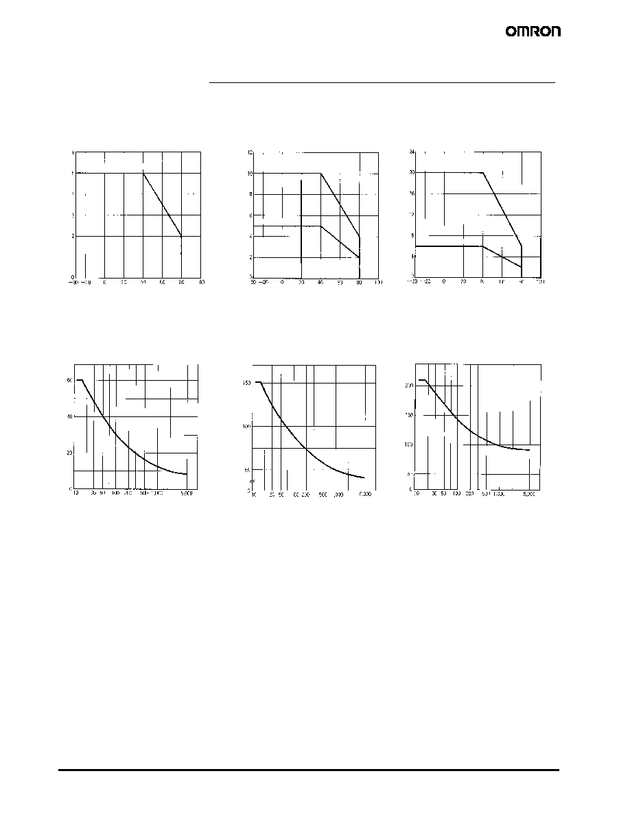
Engineering Data
Load Current vs. Ambient
Temperature Characteristics
G3NE-205T(L)-US
G3NE-210T(L)-US
G3NE-220T(L)-US
Ambient temperature (∞C)
Ambient temperature (∞C)
Ambient temperature (∞C)
Load
c
urrent
(A)
Load
c
urrent
(A)
Load
c
urrent
(A)
Without heat sink
Without heat sink
With standard heat sink (Y92B-N50)
or aluminum plate measuring 100 mm
x 100 mm x 2 mm (W x H x D)
Without heat sink
With standard heat sink (Y92B-N100) or
aluminum plate measuring 300 mm x
300 mm x 2 mm (W x H x D)
Inrush Current Resistivity
Non-repetitive (Keep the inrush current to half the rated value if it occurs repetitively.)
G3NE-205T(L)-US
G3NE-210T(L)-US
G3NE-220T(L)-US
Inrus
h
c
urrent
(A.
P
eak
)
Energizing time (ms)
Inrus
h
c
urrent
(A.
P
eak
)
Energizing time (ms)
Inrus
h
c
urrent
(A.
P
eak
)
Energizing time (ms)

4
Solid State Relay
G3NE
Dimensions
Unit: mm (inch)
G3NE-205T(L)/210T(L)/220T(L)-US
Mounting Holes
Terminal Arrangement/
Internal Connections
(Top View)
Two, 3.5-dia. or M3 holes
30±0.2
3 +
4 --
1
2
Input
Input
voltage
Load power
supply
Load
Input
14.5
6.5
7.1
2.9
7.95
3
6
37.5 max.
47.5
max.
3.5 dia. hole
11.5 max.
Two #110 (t = 0.5) (Faston
tab or equivalent)
Two #250 (t = 0.8) (Faston
tab or equivalent)
30±0.5
Mounting Holes
Heat Sink
Y92B-N50
4.6 dia.
Two, M3 holes
Two, M4 holes
5.6
47.6
77 max.
90±0.3
100 max.
35 30.5±0.3
44 max. 30
5
4.5
6
47 max.
Two, 3.2-dia.
holes
35±0.2
90±0.4
Two, 4.4-dia.
or M4 holes
Weight: approx. 200 g
51 max.
Y92B-N100
4.6 dia.
Two, M3 holes
Two, M4
holes
35 30.5±0.3
47.6
77 max.
90±0.3
100 max.
5.6
30
71 max.
5
100 max.
4.5
75 max.
Two, 3.2-dia. holes
35±0.2
90±0.4
Two, 4.4-dia.
or M4 holes
Mounting Holes
Weight: approx. 400 g
28
13
5
Solid State Relay
G3NE
J
APPROVALS
UL (File No. E64562)/CSA File No. LR35535
Input voltage
SSR type
Output ratings
5, 12, 24 VDC
G3NE--205
5 A resistive 240 VAC, 3 A Tungsten 240 VAC, 3.2 A FLA 19.2 A LRA 240 VAC, 50/60 Hz
G3NE--210
10 A resistive 240 VAC, 7.5 A Tungsten 240 VAC, 4.8 A FLA 28.8 A LRA 240 VAC, 50/60 Hz
G3NE--210
5 A resistive 240 VAC, 5 A Tungsten 240 VAC, 3 A FLA, 18 A LRA, 240 VAC, 50/60 Hz
G3NE--220
20 A resistive 240 VAC, 11 A Tungsten 240 VAC, 11.1 FLA, 66.6 LRA, 240 VAC, 50/60 Hz
G3NE--220
6 A resistive 240 VAC, 6 A Tungsten 240 VAC, 3.3 FLA, 19.8 LRA, 240 VAC, 50/60 Hz
Precautions
Refer to the pages at the back of the catalog for general precautions.
Although the LOAD terminal are internally connected to a snubber
circuit that absorbs noises, do not wire power lines or high-tension
lines with the load connecting lines of the G3NE in the same conduit
or the G3NE may be damaged or malfunction.
Because the operation time of the G3NE is extremely short, take
measures to suppress noise induced between the INPUT terminals.
If generation of strong noise is expected, connect an external noise
absorber such as an RC circuit.
Do not apply excessive force to the terminals. Exercise care when
pulling or inserting the terminal clips.
When attaching a heat sink to the G3NE, apply heat conductive
grease on the heat sink. Tighten the mounting screws of the heat
sink with a torque of 0.59 to 0.98 N-m.
NOTE: DIMENSIONS SHOWN ARE IN MILLIMETERS. To convert millimeters to inches divide by 25.4.
6
Solid State Relay
G3NE
OMRON ON-LINE
Global - http://www.omron.com
USA - http://www.omron.com/oei
Canada - http://www.omron.ca
ALL DIMENSIONS SHOWN ARE IN MILLIMETERS. To convert millimeters into inches, divide by 25.4
Cat. No. GC RLY8
5/03 Specifications subject to change without notice Printed in USA
OMRON CANADA, INC.
885 Milner Avenue
Toronto, Ontario M1B 5V8
416-286-6465
OMRON ELECTRONICS LLC
One Commerce Drive
Schaumburg, IL 60173
847-882-2288