Document Outline
- Front Page
- Ordering Information
- Application Example
- Specifications
- Engineering Data
- Dimensions
- Precautions
- Contact Omron Information
1
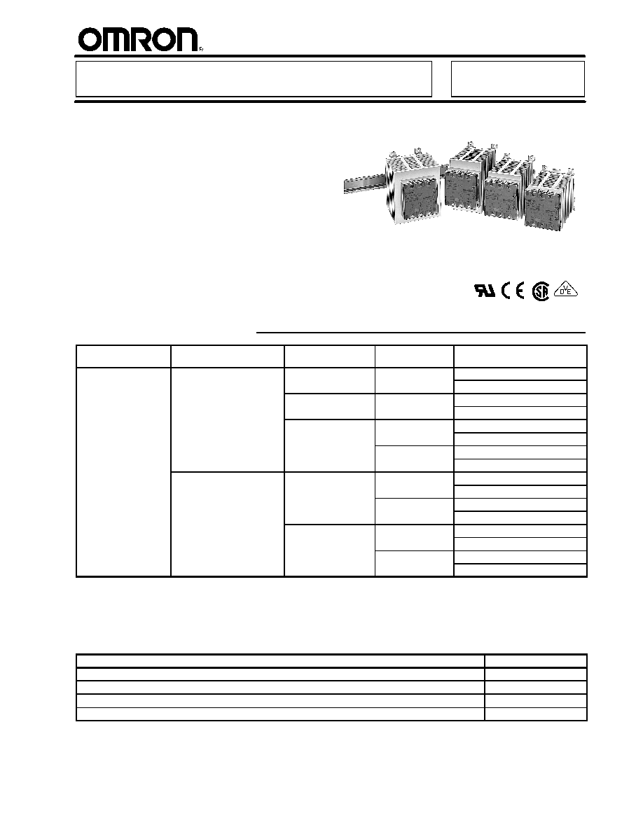
Industrial 3--Phase Solid State Relay
G3PB
H
A comprehensive lineup that now includes
480-VAC models
H
Used to switch electrical loads including
Omron's temperature coltrollers
H
No audible noise; EMI (Electro-Magnetic
Interference) and vibration resistant
H
Improved heat sink increases life and
reliability
H
Voltage turn-on at zero crossing reduces
initial inrush load currents
H
LED indicator turns on when control power
is applied
H
DIN rail or panel mountable
Ordering Information
Input operating voltage
(Rated voltage)
Operating load voltage
(Rated load voltage)
Max. inrush current
(60Hz, 1 cycle)
Max. load current
Part number
9.6 to 30 VDC
(12
2 VDC)
75 to 264 VAC
(100
2 0 VAC)
150A
15 amps
G3PB-215B-3N-VD DC12--24V
(12 to 24 VDC)
(100 to 240 VAC)
p
G3PB-215B-2N-VD DC12--24V
220A
25 amps
G3PB-225B-3N-VD DC12--24V
p
G3PB-225B-2N-VD DC12--24V
440A
35 amps
G3PB-235B-3N-VD DC12--24V
p
G3PB-235B-2N-VD DC12--24V
45 amps
G3PB-245B-3N-VD DC12--24V
p
G3PB-245B-2N-VD DC12--24V
180 to 528 VAC
(200
80 VAC)
220A
15 amps
G3PB-515B-3N-VD DC12--24V
(200 to 480 VAC)
p
G3PB-515B-2N-VD DC12--24V
25 amps
G3PB-525B-3N-VD DC12--24V
p
G3PB-525B-2N-VD DC12--24V
440A
35 amps
G3PB-535B-3N-VD DC12--24V
p
G3PB-535B-2N-VD DC12--24V
45 amps
G3PB-545B-3N-VD DC12--24V
p
G3PB-545B-2N-VD DC12--24V
Note: 1. All models have zero cross function.
2. Number of poles indicated by --2N (for two poles) or --3N (for three poles) in part number.
J
Accessories
DIN Rail Mounting Track
Description
Part number
DIN rail track, 7.3 mm (0.29 in) depth; 50 cm (1.64 ft) length
PFP-50N
DIN rail track, 7.3 mm (0.29 in) depth; 1 m (3.28 ft) length
PFP-100N
End plate
PFP-M
Spacer
PFP-S
G3PB
G3PB
2
Application Example
Load
Heater
Power supply
for load
Direct connection possible
Temperature Controller
Voltage output
terminal
(for driving SSR)
SSR
Input
Output
Omron's SSRs offer these advantages over electro-mechanical relays (EMRs):
D
Longer service life with no contacts to wear out
D
Reduced electromagnetic interference
D
Faster response time
D
Vibration and shock resistance
D
No audible noise when switching
D
Enhanced reliability
Specifications
J
Ratings (at an Ambient Temperature of 25�C)
Operating Circuit (Common)
Item
Common
Rated operating voltage
12 to 24 VDC
Operating voltage range
9.6 to 30 VDC
Rated input current (Impedance)
10 mA max. (at 24 VDC)
Must-operate voltage
9.6 VDC max.
Reset voltage
1 VDC min.
Insulation method
Phototriac coupler
Operation indicator
Yellow LED
Output
Item
G3PB-
215B-
3N-VD
G3PB-
215B-
2N-VD
G3PB-
225B-
3N-VD
G3PB-
225B-
2N-VD
G3PB-
235B-
3N-VD
G3PB-
235B-
2N-VD
G3PB-
245B-
3N-VD
G3PB-
245B-
2N-VD
Rated voltage
100 to 240 VAC
Operating voltage range
75 to 264 VAC
Rated carry current
(see note)
15 A
25 A
35 A
45 A
Minimum load current
0.2 A
0.5 A
Inrush current resistance
(peak value)
150 A
(60 Hz, 1 cycle)
220 A
(60 Hz, 1 cycle)
440 A
(60 Hz, 1 cycle)
Permissible I
2
t
(half 60-Hz wave)
121 A
2
s
260 A
2
s
1,260 A
2
s
Item
G3PB-
515B-
3N-VD
G3PB-
515B-
2N-VD
G3PB-
525B-
3N-VD
G3PB-
525B-
2N-VD
G3PB-
535B-
3N-VD
G3PB-
535B-
2N-VD
G3PB-
545B-
3N-VD
G3PB-
545B-
2N-VD
Rated voltage
200 to 480 VAC
Operating voltage range
180 to 528 VAC
Rated carry current
(see note)
15 A
25 A
35 A
45 A
Minimum load current
0.5 A
Inrush current resistance
(peak value)
220 A
(60 Hz, 1 cycle)
440 A
(60 Hz, 1 cycle)
Permissible I
2
t
(half 60-Hz wave)
260 A
2
s
1,260 A
2
s
G3PB
G3PB
3
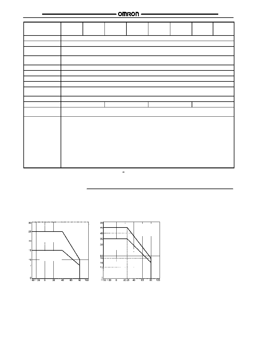
Note: Rated carry current varies depending on the ambient temperature. For details, refer to Load Current vs. Ambient Temperature in
Engineering Data.
J
Characteristics
Item
G3PB-
215B-
3N-VD
G3PB-
215B-
2N-VD
G3PB-
225B-
3N-VD
G3PB-
225B-
2N-VD
G3PB-
235B-
3N-VD
G3PB-
235B-
2N-VD
G3PB-
245B-
3N-VD
G3PB-
245B-
2N-VD
Operate time
1/2 of load power source cycle + 1 ms max. (DC input)
Release time
1/2 of load power source cycle + 1 ms max. (DC input)
Output ON voltage
drop
1.6 V (RMS) max.
Leakage current
(see note)
10 mA (at 200 VAC)
Insulation resistance
100 M min. (at 500 VDC)
Dielectric strength
2,500 VAC, 50/60 Hz for 1 min
Vibration resistance
10 to 55 Hz, 0.175-mm single amplitude
Shock resistance
294 m/s
2
(98 m/s
2
with reverse mounting)
Ambient temperature
Operating: --30�C to 80�C (--22�F to 176�F) with no icing or condensation
Storage:
--30�C to 100�C (--30�F to 2121�F) with no icing or condensation
Ambient humidity
Operating: 45% to 85%
Weight
Approx. 1.25 kg (2.75 lbs)
Approx. 1.45 kg (3.20 lbs)
Approx. 1.65 kg (3.64 lbs)
Approx. 2.0 kg (4.41 lbs)
Approved standards
UL508, CSA22.2 No. 14, EN60947-4-3 (IEC947-4-3) approved by VDE
(From April 2001)
EMC
Emission
EN55011 Group 1 Class B
Immunity
ESD
IEC947-4-3, EN61000-4-2
4 kV contact discharge
8 kV air discharge
Immunity
Electromagnetic
IEC947-4-3, EN61000-4-3
10 V/m (80 MHz to 1 GHz)
Immunity
EFT
IEC947-4-3, EN61000-4-4
2 kV AC power-signal line
Immunity
Surge transient
IEC947-4-3, EN61000-4-5
Normal mode �1 kV, Common mode �2 kV
Immunity
RF disturbance
IEC947-4-3, EN61000-4-6
10 V (0.15 to 80 MHz)
Immunity
Dips
IEC947-4-3, EN61000-4-11
Note:
The leakage current of phase S will be approximately
times larger if the 2-element model is applied.
3
G3PB
G3PB
4
Item
G3PB-
515B-
3N-VD
G3PB-
515B-
2N-VD
G3PB-
525B-
3N-VD
G3PB-
525B-
2N-VD
G3PB-
535B-
3N-VD
G3PB-
535B-
2N-VD
G3PB-
545B-
3N-VD
G3PB-
545B-
2N-VD
Operate time
1/2 of load power source cycle + 1 ms max. (DC input)
Release time
1/2 of load power source cycle + 1 ms max. (DC input)
Output ON voltage
drop
1.8 V (RMS) max.
Leakage current
(see note)
20 mA (at 480 VAC)
Insulation resistance
100 M min. (at 500 VDC)
Dielectric strength
2,500 VAC, 50/60 Hz for 1 min
Vibration resistance
10 to 55 Hz, 0.175-mm single amplitude
Shock resistance
294 m/s
2
(98 m/s
2
with reverse mounting)
Ambient temperature
Operating: --30�C to 80�C (--22�F to 176�F) with no icing or condensation
Storage:
--30�C to 100�C (--30�F to 2121�F) with no icing or condensation
Ambient humidity
Operating: 45% to 85%
Weight
Approx. 1.25 kg (2.75 lbs)
Approx. 1.45 kg (3.20 lbs)
Approx. 1.65 kg (3.64 lbs)
Approx. 2.0 kg (4.41 lbs)
Approved standards
UL508, CSA22.2 No. 14, EN60947-4-3 (IEC947-4-3) approved by VDE
(From April 2001)
EMC
Emission
EN55011 Group 1 Class B
Immunity
ESD
IEC947-4-3, EN61000-4-2
4 kV contact discharge
8 kV air discharge
Immunity
Electromagnetic
IEC947-4-3, EN61000-4-3
10 V/m (80 MHz to 1 GHz)
Immunity
EFT
IEC947-4-3, EN61000-4-4
2 kV AC power-signal line
Immunity
Surge transient
IEC947-4-3, EN61000-4-5
Normal mode �1 kV, Common mode �2 kV
Immunity
RF disturbance
IEC947-4-3, EN61000-4-6
10 V (0.15 to 80 MHz)
Immunity
Dips
IEC947-4-3, EN61000-4-11
Note:
The leakage current of phase S will be approximately
times larger if the 2-element model is applied.
3
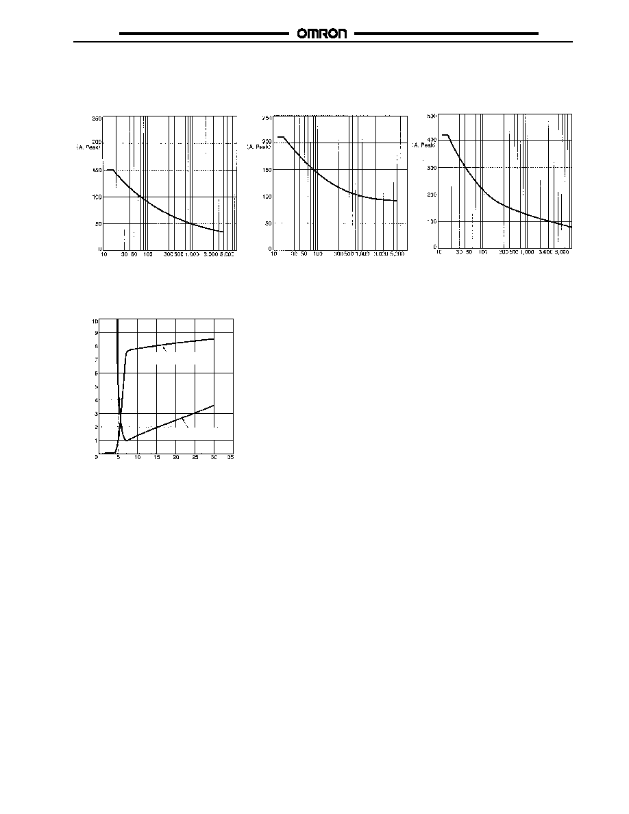
Engineering Data
J
Load Current vs. Ambient Temperature (Continuous Input)
G3PB-215B-3N-VD
G3PB-215B-2N-VD
G3PB-515B-3N-VD
G3PB-515B-2N-VD
G3PB-225B-3N-VD
G3PB-225B-2N-VD
G3PB-525B-3N-VD
G3PB-525B-2N-VD
G3PB-245B-3N-VD
G3PB-245B-2N-VD
G3PB-545B-3N-VD
G3PB-545B-2N-VD
G3PB-235B-3N-VD
G3PB-235B-2N-VD
G3PB-535B-3N-VD
G3PB-535B-2N-VD
G3PB-225B-3N-VD
G3PB-225B-2N-VD
G3PB-525B-3N-VD
G3PB-525B-2N-VD
G3PB-215B-3N-VD
G3PB-215B-2N-VD
G3PB-515B-3N-VD
G3PB-515B-2N-VD
Load
c
u
r
r
ent
(
A
)
Ambient temperature (_C)
G3PB-245B-3N-VD
G3PB-245B-2N-VD
G3PB-545B-3N-VD
G3PB-545B-2N-VD
G3PB-235B-3N-VD
G3PB-235B-2N-VD
G3PB-535B-3N-VD
G3PB-535B-2N-VD
Ambient temperature (_C)
Load
c
u
r
r
ent
(
A
)
G3PB
G3PB
5
J
Inrush Current Resistivity: Non-repetitive (Less than Half for Repetitive)
G3PB-215B-3N-VD
G3PB-215B-2N-VD
G3PB-225B-3N-VD
G3PB-225B-2N-VD
G3PB-515B-3N-VD
G3PB-515B-2N-VD
G3PB-525B-3N-VD
G3PB-525B-2N-VD
G3PB-245B-3N-VD
G3PB-245B-2N-VD
G3PB-545B-3N-VD
G3PB-545B-2N-VD
G3PB-235B-3N-VD
G3PB-235B-2N-VD
G3PB-535B-3N-VD
G3PB-535B-2N-VD
I
n
r
u
sh
cu
r
r
e
n
t
Energized time (ms)
Energized time (ms)
Energized time (ms)
I
n
r
u
sh
cu
r
r
e
n
t
I
n
r
u
sh
cu
r
r
e
n
t
J
Input Voltage vs. Input Current and Input Voltage vs. Input Impedance
Input voltage (V)
I
nput
c
u
r
r
ent
(
m
A
)
I
nput
impedanc
e
(
k
)
Input current
Input impedance
G3PB
G3PB
6
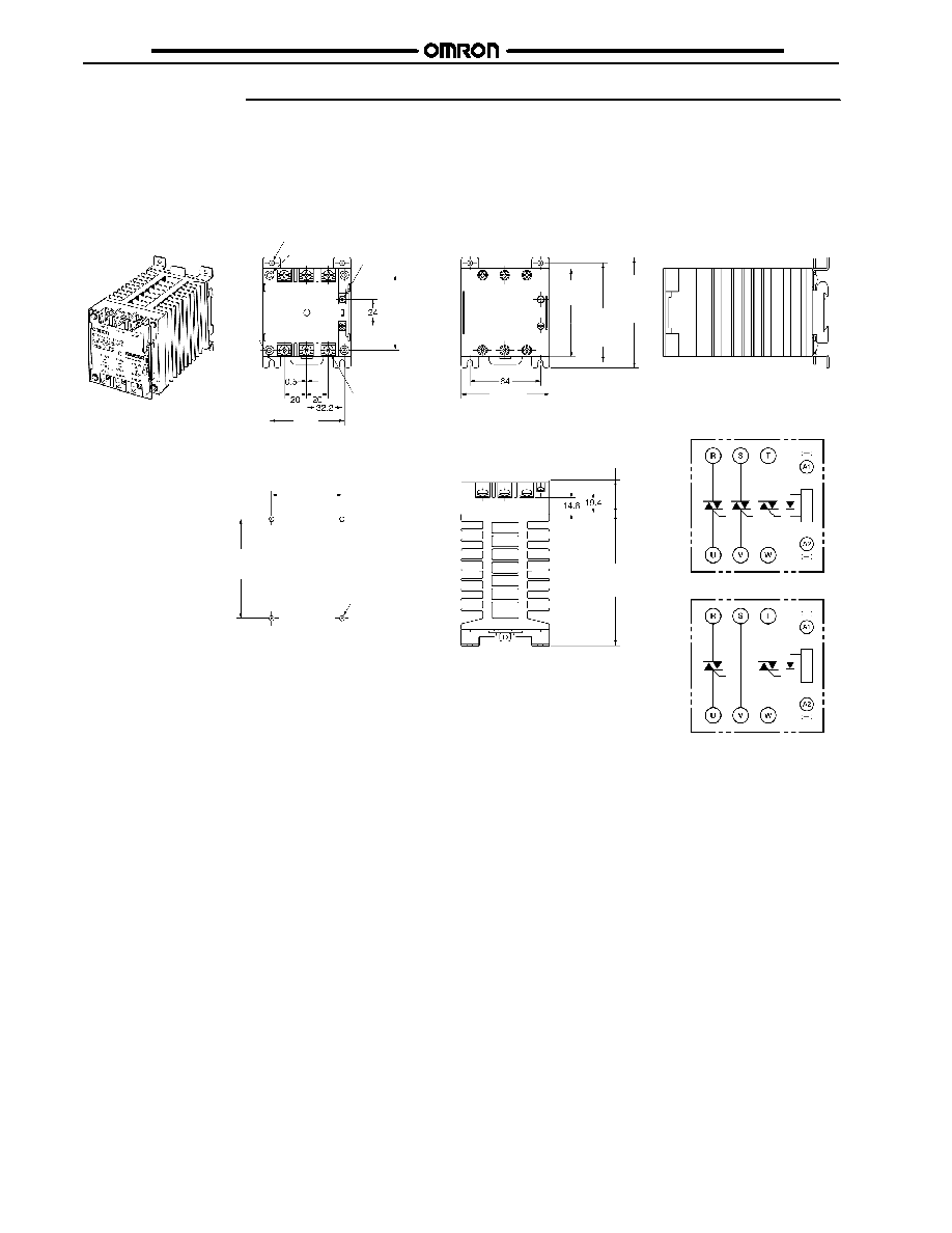
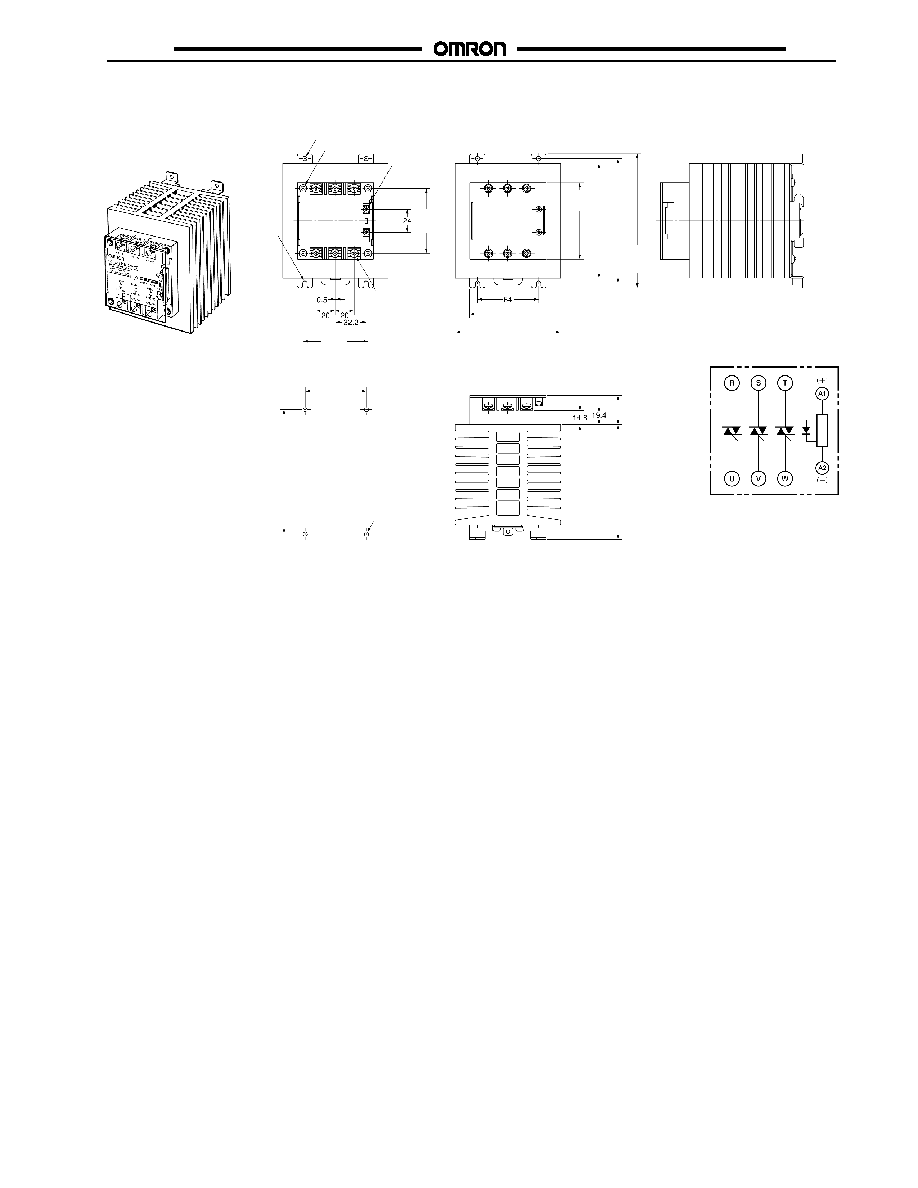
Dimensions
Unit: mm (inch)
G3PB-215B-3N-VD
G3PB-515B-3N-VD
G3PB-215B-2N-VD
G3PB-515B-2N-VD
G3PB-225B-2N-VD
G3PB-525B-2N-VD
Two, 4.6-dia. mounting holes
Four, 8 dia.
Two, R2.3
mounting
holes
80 max.
(3.15)
100 max.
(3.94)
80.5 max.
(3.17)
Mounting Hole Dimensions
Four, 4.5-dia. or M4
30.5 max.
(1.20)
120 max.
(4.72)
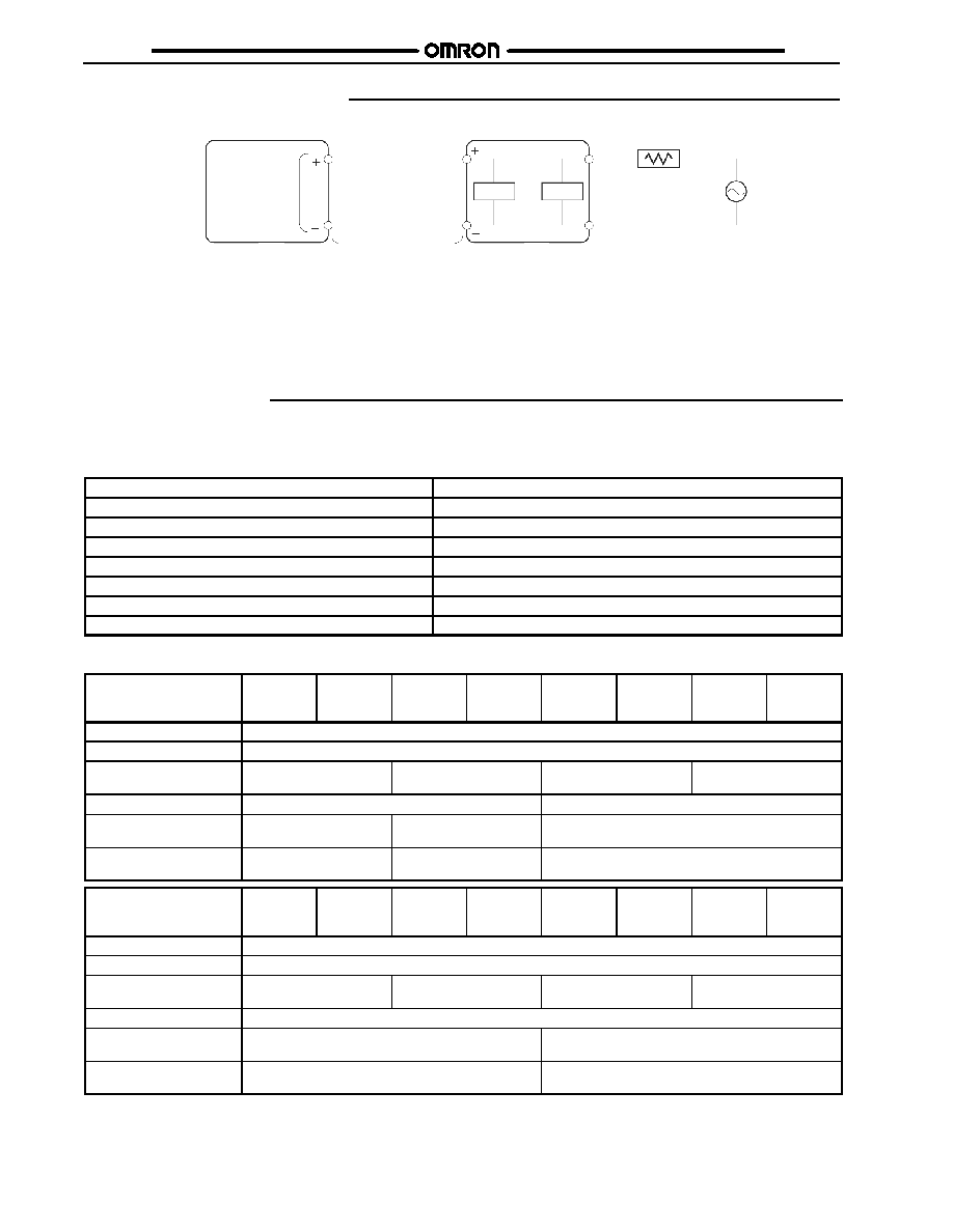
Terminal Arrangement/
Internal Connections
G3PB-jjjB-3N-VD
G3PB-jjjB-2N-VD
I
nput
c
i
r
c
uit
I
nput
c
i
r
c
uit
Without Terminal Cover
With Terminal Cover
Two, M3.5
Six, M4
68
(2.68)
90
(3.17)
90 �0.3
(3.54 �0.012)
68
(2.68)
64 �0.3
(2.52 �0.012)
G3PB
G3PB
7
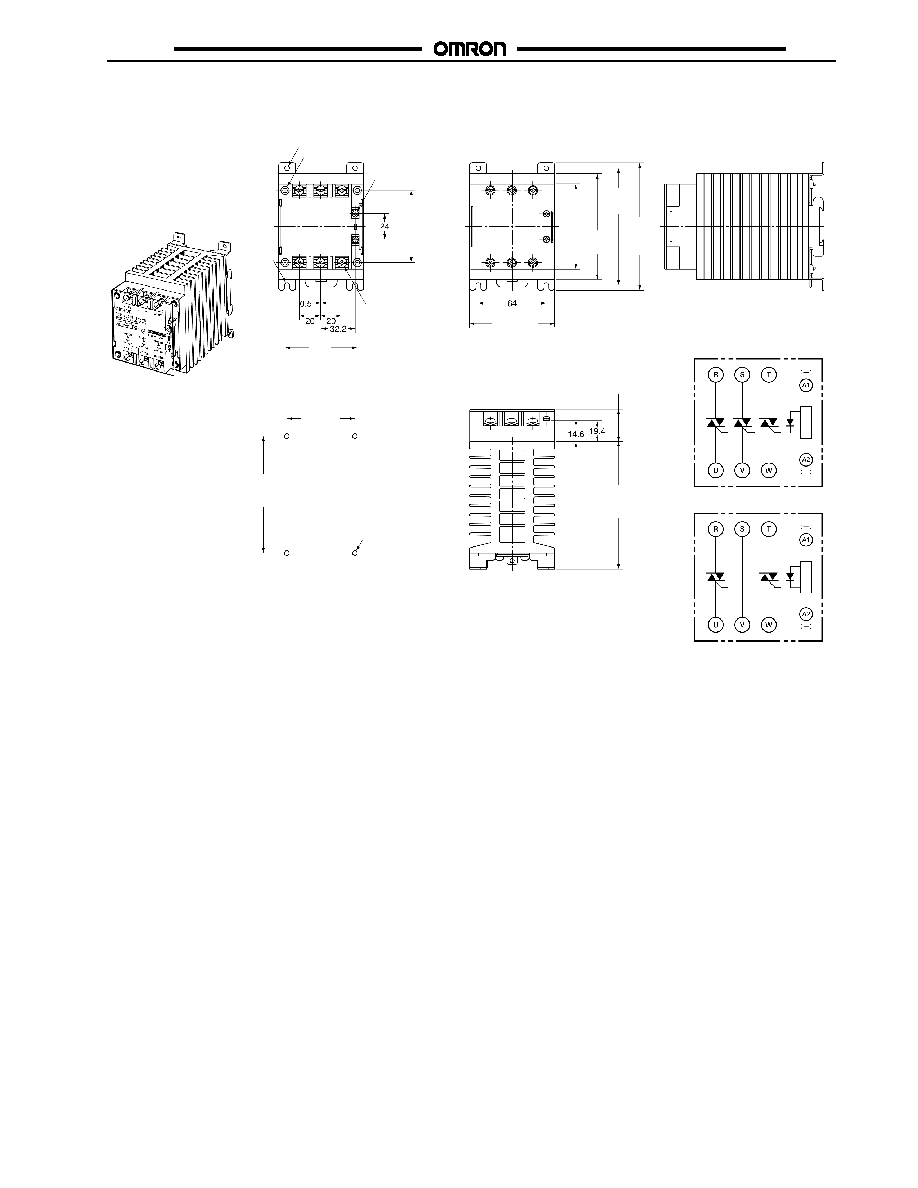
Unit: mm (inch)
G3PB-225B-3N-VD
G3PB-235B-2N-VD
G3PB-525B-3N-VD
G3PB-535B-2N-VD
Two, 4.6-dia. mounting holes
Four, 8 dia.
Two, R2.3
mounting
holes
120 max.
(4.72)
80.5 max.
(3.17)
Mounting Hole Dimensions
30.5 max.
(1.20)
120 max.
(4.72)
Terminal Arrangement/
Internal Connections
G3PB-jjjB-3N-VD
G3PB-jjjB-2N-VD
I
nput
c
i
r
c
uit
I
nput
c
i
r
c
uit
Without Terminal Cover
With Terminal Cover
Four, 4.5-dia. or M4
Six, M5 (35 A type)
Six, M4 (25 A type)
Two, M3.5
80 max.
(3.15)
110
(4.33)
100
(3.94)
68
(2.68)
110 �0.3
(4.33 �0.012)
64 �0.3
(2.52 �0.012)
68
(2.68)
G3PB
G3PB
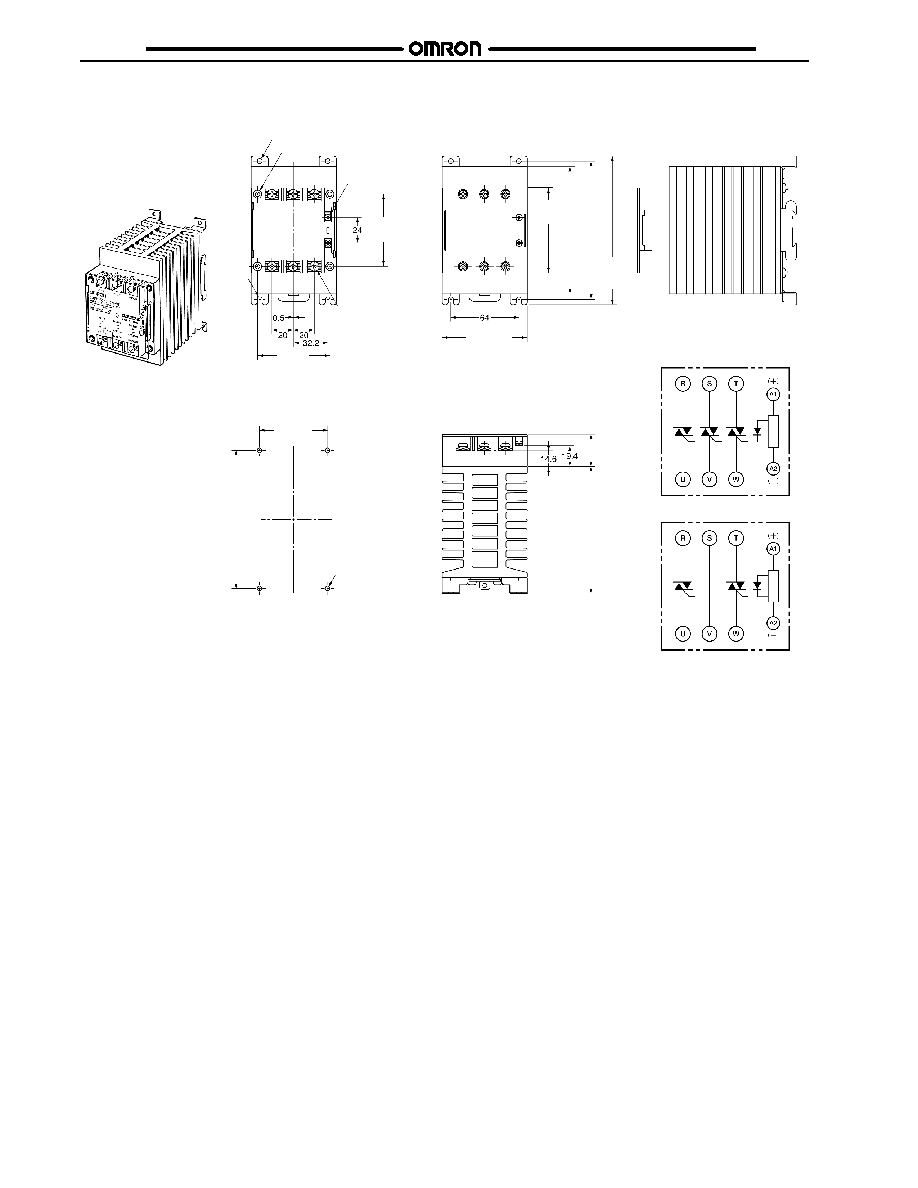
8
Unit: mm (inch)
G3PB-235B-3N-VD
G3PB-245B-2N-VD
G3PB-535B-3N-VD
G3PB-545B-2N-VD
Two, 4.6-dia. mounting holes
Four, 8 dia.
140 max.
(5.51)
30.5 max.
(1.20)
G3PB-jjjB-3N-VD
G3PB-jjjB-2N-VD
Two, R2.3
mounting
holes
Four, 4.5-dia. or M4
Without Terminal Cover
With Terminal Cover
Terminal Arrangement/
Internal Connections
I
nput
c
i
r
c
uit
I
nput
c
i
r
c
uit
Mounting Hole Dimensions
Two, M3.5
Six, M5
80.5 max.
(3.17)
120 max.
(4.72)
80 max.
(3.15)
120
(4.72)
130 �0.3
(5.12 �0.012)
64 �0.3
(2.52 �0.012)
68
(2.68)
68
(2.68)
130
(5.12)
G3PB
G3PB
9
Unit: mm (inch)
G3PB-245B-3N-VD
G3PB-545B-3N-VD
Four, 8 dia.
G3PB-jjjB-3N-VD
110 max.
(4.33)
Two, 4.6-dia. mounting holes
Two, R2.3
mounting
holes
Without Terminal Cover
With Terminal Cover
Mounting Hole Dimensions
Four, 4.5-dia.
or M4
Terminal Arrangement/
Internal Connections
I
nput
c
i
r
c
uit
Two, M3.5
Six, M5
140 max.
(5.51)
30.5 max.
(1.20)
80.5 max.
(3.17)
120 max.
(4.72)
80 max.
(3.15)
120
(4.72)
130 �0.3
(5.12 �0.012)
64 �0.3
(2.52 �0.012)
68
(2.68)
68
(2.68)
130
(5.12)

G3PB
G3PB
10
Precautions
Do not touch the terminals (i.e., charged parts) of the G3PB
while power is supplied, otherwise an electric shock may be
received.
If the G3PB is provided with a terminal cover, be sure to attach
the terminal cover to the G3PB before operating the G3PB.
WARNING
WARNING
The G3PB and radiator are very hot while power is supplied to
the G3PB.
Do not touch the G3PB or the radiator while power is supplied
to the G3PB or immediately after the G3PB is turned OFF,
otherwise a burn may result.
WARNING
Do not touch main circuit terminal of the G3PB immediately af-
ter the G3PB is turned OFF, otherwise an electric shock may
be received due to the residual charge of the built-in snubber
circuit.
WARNING
Be sure to turn OFF the power supply to the G3PB before wir-
ing, otherwise an electric shock may be received.
Mount the terminal cover to the G3PB after wiring.
Do not touch the terminals of the G3PB while power is sup-
plied, otherwise an electric shock may be received.
WARNING
Ensure that a short-circuit current does not flow on the load
side of the SSR, otherwise the G3PB may be damaged.
J
General Precautions
At OMRON, we are constantly working to improve the quality and
reliability of our products. SSRs, however, use semiconductors,
which are prone to malfunction. Be sure to use SSRs within their
rated values.
Use the SSR only in systems that are designed with redundan-
cies, flame protection, counter measures to prevent operation
errors, and other countermeasures to prevent accidents involving
human life or fires.
1. Do not apply voltages or currents to the G3PB's terminals
in excess of the rated values. Doing so may result in
malfunction or burning.
2. Do not use the G3PB with terminal screws not properly
tightened. Abnormal heating of the terminals may result in
burning.
3. Do not obstruct the flow of air around the G3PB and the
radiator. Abnormal heating of the G3PB may result
short-circuiting of output elements and burning.
4. Perform wiring and tighten screws according to the
instructions given under Correct Use. Using the G3PB with
incorrect wiring or with the screws not tightened properly
may result in burning due to abnormal heating of the G3PB
during use.
J
Correct Use
Before Actual Operation
�
The G3PB in operation may cause an unexpected accident.
Therefore it is necessary to test the G3PB under a variety of
conditions that are possible. As for the characteristics of the
G3PB, it is necessary to consider differences in
characteristics between G3PB Units.
�
The ratings in this datasheet are tested values in a
temperature range between 15�C and 30�C, a relative
humidity range between 25% and 85%, and an atmospheric
pressure range between 88 and 106 kPa. It will be necessary
to provide the above conditions as well as the load conditions
if the user wants to confirm the ratings of actual G3PB Units.
Mounting Method
Since the Relay is heavy, firmly mount the DIN track and fix both
ends with End Plates for DIN-track-mounting models.
Applicable DIN Tracks
The G3PB can be mounted to TH35-15Fe (IEC60715) DIN
tracks. The manufacturers and models of DIN tracks to which
mounting is possible are shown in the following table.
Manufacturer
Thickness
1.5 mm
2.3 mm
Schneider
AM1-DE200
---
WAGO
210-114, 210-197
210-118
PHOENIX
NS35/15
NS35/15-2.3
Direct Mounting
When mounting directly onto a panel, mount securely under the
following conditions.
Screw diameter: M4
Tightening torque: 0.98 to 1.47 N S m
Mounted State
Vertical Mounting
Horizontal Mounting
V
e
r
t
i
c
al
di
r
e
c
t
i
o
n
Panel
Panel
Note: Mount the G3PB so
that the markings
can be read.
Note: When the G3PB is
mounted horizontally,
use at 50% of the rated
load current.
Wiring duct
80 mm min.
80 mm min.
Wiring duct
Close Mounting
!
!
!
!
!
G3PB
G3PB
11
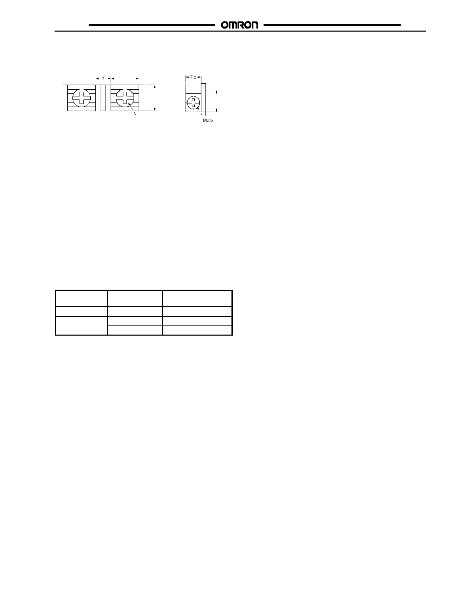
Wiring
When using crimp terminals, refer to the terminal clearances
shown below.
Output Terminals
Input Terminals
M4 (15 A, 25 A)
M5 (35 A, 45 A)
13
(0.51)
12
(0.47)
10
(0.39)
�
Be sure that all lead wires are thick enough according to the
current.
�
Output terminals T1, T2, and T3 are charged regardless of
whether the Unit is a 2- or 3-element model that is turned on
or off. Do not touch these terminals, otherwise an electric
shock may be received.
To isolate the Unit from the power supply, install an appropri-
ate circuit breaker between the power supply and Unit.
Be sure to turn off the power supply before wiring the Unit.
�
Terminal L2 and terminal T2 of the 2-element model are
internally short-circuited to each other. Therefore, connect
terminal L2 to the ground terminal side of the power supply. If
terminal L2 is connected to a terminal other than the ground
terminal, cover all the charged terminals, such as heater
terminals, for the prevention of electric shock accidents and
ground faults.
Tightening Torque
Refer to the following and be sure to tighten each screw of the
Unit to the specified torque in order to prevent the Unit from mal-
functioning.
Item
Screw terminal
diameter
Tightening torque
Input terminal
M3.5
0.59 to 1.18 N S m
Output terminal
M4
0.98 to 1.47 N S m
p
M5
1.47 to 2.45 N S m
Operating Conditions
�
Do not apply current exceeding the rated current otherwise,
the temperature of the G3PB may rise excessively.
�
Be sure to prevent the ambient temperature rising due to the
heat radiation of the G3PB. If the G3PB is mounted inside a
panel, install a fan so that the interior of the panel is fully
ventilated.
�
Do not use the G3PB if heat dissipation fins have been bent
as a result of, for example, dropping the G3PB. If used in this
state, the G3PB may be damaged due to the decreased heat
dissipation capacity.
�
Only use the G3PB with loads that are within the rated values.
Using the G3PB with loads outside the rated values may
result in malfunction, damage, or burning.
�
Use a power supply within the rated frequency range. Using a
power supply outside the rated frequency range may result in
malfunction, damage, or burning.
�
Keep wiring separate from high-voltage power lines and use
wires of an appropriate length, otherwise malfunction and
damage may result due to induction.
�
As protection against accidents due to short-circuiting, be sure
to install protective devices, such as fuses and no-fuse
breakers on the power supply side.
J
Operating and Storage Environments
Operating Ambient Temperature
The rated value for the ambient operating temperature of the
G3PB is for when there is no built-up heat. For this reason, under
conditions where heat dissipation is not good due to poor ventila-
tion, and where heat may build up easily, the actual temperature
of the G3PB may exceed the rated value resulting in malfunction
on burning.
When using the G3PB, design the system to allow heat dissipa-
tion sufficient to stay below the Load Current vs. Ambient Tem-
perature characteristic curve. Note also that the ambient temper-
ature of the G3PB may increase as a result of environmental
conditions (e.g., climate, air-conditioning) and operating condi-
tions (e.g., mounting in an airtight panel).
Operating and Storage Locations
Do not use or store the G3PB in the following locations. Doing so
may result in damage, malfunction, or deterioration of perfor-
mance characteristics.
�
Do not use or store in locations subject to direct sunlight.
�
Do not use in locations subject to ambient temperatures
outside the range --20 to 60�C (--4�F to 140�F).
�
Do not use in locations subject to relative humidity outside the
range 45% to 85% or locations subject to condensation as the
result of severe changes in temperature.
�
Do not store in locations subject to ambient temperatures
outside the range --30 to 70�C (--22�F to 158�F).
�
Do not use or store in locations subject to corrosive or
flammable gases.
�
Do not use or store in locations subject to dust (especially iron
dust) or salts.
�
Do not use or store in locations subject to shock or vibration.
�
Do not use or store in locations subject to exposure to water,
oil, or chemicals.
Transportation
When transporting the G3PB, observe the following points. Not
doing so may result in damage, malfunction, or deterioration of
performance characteristics.
�
Do not drop the G3PB or subject it to severe vibrations or
shock.
�
Do not transport the product if it is wet.
Vibration and Shock
Do not subject the SSR to excessive vibration or shock. Other-
wise the SSR may malfunction and internal components may be
damaged.
To prevent the SSR from abnormal vibration, do not install the
G3PB in locations or by means that will subject it to the vibrations
from other devices, such as motors.
Solvents
Do not allow the G3PB to come in contact with solvents such as
thinners or gasoline. Doing so will dissolve the markings on the
SSR.
Oil
Do not allow the G3PB terminal cover to come in contact with oil.
Doing so will cause the cover to crack and become cloudy.
G3PB
G3PB
12
J
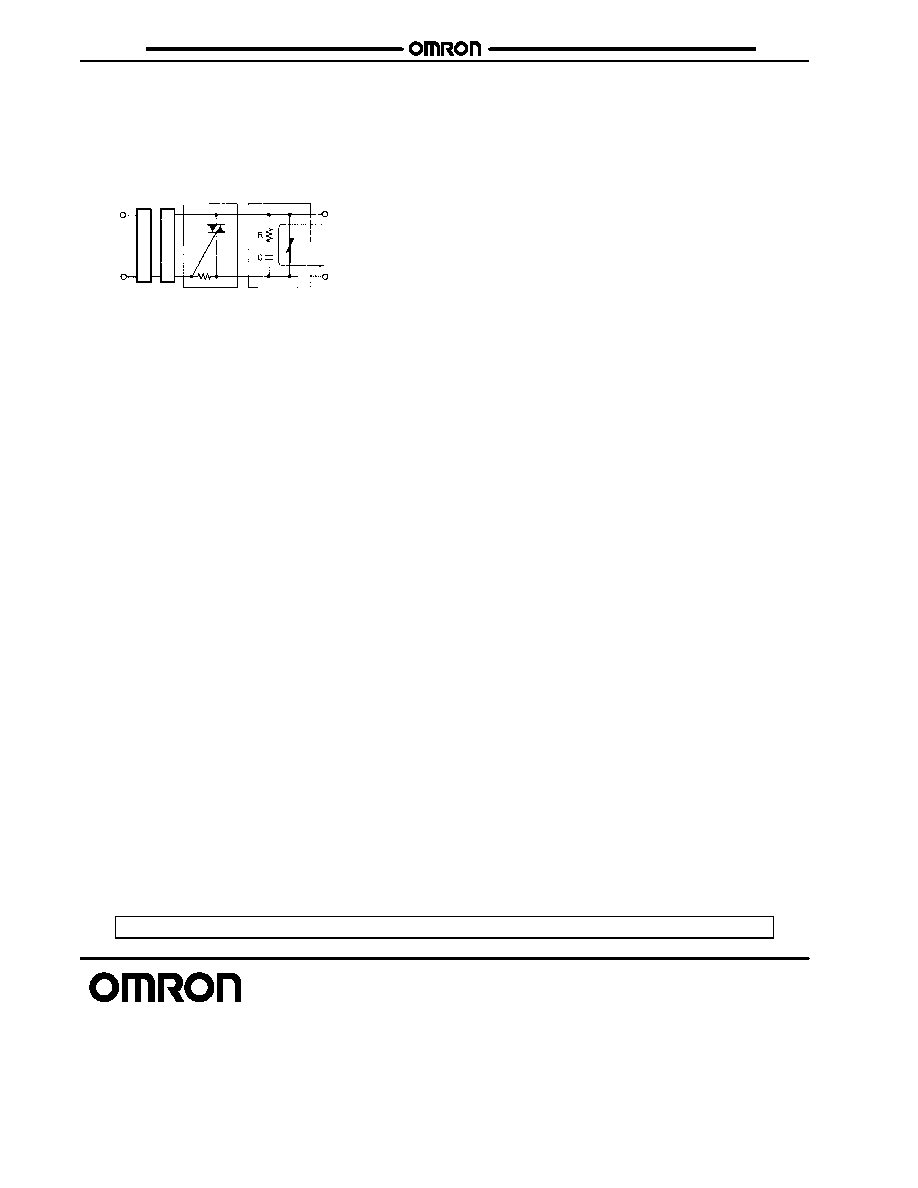
Operation
Leakage Current
A leakage current flows through a snubber circuit in the G3PB
even when there is no input. Therefore, always turn OFF the
power to the input or load and check that it is safe before replac-
ing or wiring the G3PB.
Switch element Snubber circuit
Input
c
i
r
c
ui
t
T
r
ig
g
e
r
c
ir
cu
it
Va
r
i
s
t
o
r
Leakage current
Screw Tightening Torque
Tighten the G3PB terminal screws properly. If the screws are not
tight, the G3PB will be damaged by heat generated when the
power is ON.
Mounting
Do not perform mounting with oil or metal powder on your hands.
Doing so may result in damage to the G3PB.
Dropping
Be careful not to drop the G3PB during mounting. The G3PB
weighs approximately 1.25 to 2.0 kg and could cause injury if
dropped on any part of your body.
Cat.No. J112-E3-2 08/01/ 7.5 Specifications subject to change without notice. Printed in U.S.A.
OMRON ELECTRONICS LLC
One East Commerce Drive
Schaumburg, IL 60173
NOTE: DIMENSIONS SHOWN ARE IN MILLIMETERS. To convert millimeters to inches divide by 25.4.
1-800-55-OMRON
OMRON CANADA, INC.
885 Milner Avenue
Scarborough, Ontario M1B 5V8
416-286-6465
R
OMRON ON--LINE
Global -- http://www.omron.com
USA -- http://www.omron.com/oei
Canada -- http://www.omron.com/oci