78
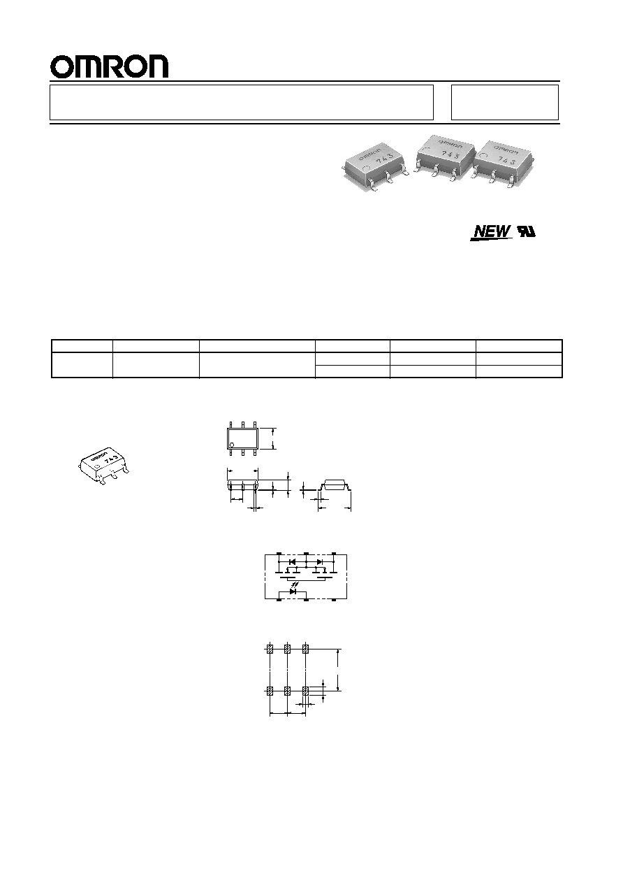
G3VM-351H
MOS FET Relays
Slim, 2.1-mm High Relay Incorporating a
MOS FET Optically Coupled with an
Infrared LED in a Miniature, Flat SOP
Package
∑ Upgraded G3VM-S3 Series.
∑ Continuous load current of 110 mA.
∑ Dielectric strength of 1,500 Vrms between I/O.
Application Examples
∑ Broadband systems
∑ Measurement devices
∑ Data loggers
∑ Amusement machines
Note:
The actual product is marked differently from the image
shown here.
List of Models
Dimensions
Note:
All units are in millimeters unless otherwise indicated.
Terminal Arrangement/Internal Connections (Top View)
Actual Mounting Pad Dimensions (Recommended Value, Top View)
Contact form
Terminals
Load voltage (peak value)
Model
Number per stick
Number per tape
SPST-NO
Surface-mounting
terminals
350 VAC
G3VM-351H
75
---
G3VM-351H(TR)
---
2,500
4.4
±
0.25
6.3
±
0.25
0.4
±
0.1
2.54
±
0.25
2.1 max.
0.1
±
0.1
7.0
±
0.4
0.6
±
0.3
0.15
G3VM-351H
Note: The actual product is
marked differently from the image shown
Weight: 0.13 g
6
5
4
1
3
2
G3VM-351H
6 to 6.3
1.2
0.8
2.54
2.54
G3VM-351H
Tel:0755-83003780 Fax:0755-83003794 www.andiantech.com

79
G3VM-351H
G3VM-351H
Absolute Maximum Ratings (Ta = 25
∞
C)
Electrical Characteristics (Ta = 25
∞
C)
Recommended Operating Conditions
Use the G3VM under the following conditions so that the Relay will operate properly.
Engineering Data
Load Current vs. Ambient Temperature
G3VM-351H
Safety Precautions
Refer to page 6 for precautions common to all G3VM models.
Item
Symbol
Rating
Unit
Measurement Conditions
Input
LED forward current
I
F
50
mA
Repetitive peak LED forward
current
I
FP
1
A
100
m
s pulses, 100 pps
LED forward current reduction
rate
D
I
F
/
∞
C
-
0.5
mA/
∞
C
Ta
≥
25
∞
C
LED reverse voltage
V
R
5
V
Connection temperature
T
j
125
∞
C
Output
Output dielectric strength
V
OFF
350
V
Continuous
load current
Connection A
I
O
110
mA
Connection B
110
Connection C
220
ON current
reduction
rate
Connection A
D
I
ON
/
∞
C
-
1.1
mA/
∞
C
Ta
≥
25
∞
C
Connection B
-
1.1
Connection C
-
2.2
Connection temperature
T
j
125
∞
C
Dielectric strength between input and
output (See note 1.)
V
I-O
1,500
Vrms
AC for 1 min
Operating temperature
T
a
-
40 to +85
∞
C
With no icing or condensation
Storage temperature
T
stg
-
55 to +125
∞
C
With no icing or condensation
Soldering temperature (10 s)
---
260
∞
C
10 s
Load
or
AC
DC
1
2
3
6
5
4
1
2
3
6
5
4
Load
DC
DC
Load
1
2
3
6
5
4
Connection Diagram
Connection
A
Connection
B
Connection
C
Note:
1. The dielectric strength between the input and
output was checked by applying voltage be-
tween all pins as a group on the LED side and
all pins as a group on the light-receiving side.
Item
Symbol
Mini-
mum
Typical
Maxi-
mum
Unit
Measurement
conditions
Input
LED forward voltage
V
F
1.0
1.15
1.3
V
I
F
= 10 mA
Reverse current
I
R
---
---
10
m
A
V
R
= 5 V
Capacity between terminals
C
T
---
30
---
pF
V = 0, f = 1 MHz
Trigger LED forward current
I
FT
---
1
3
mA
I
O
= 110 mA
Output
Maximum resistance
with output ON
Connection A
R
ON
---
25
35
W
I
F
= 5 mA,
I
O
= 110 mA, t < 1 s
---
35
50
W
I
F
= 5 mA,
I
O
= 110 mA
Connection B
---
28
40
W
I
F
= 5 mA,
I
O
= 110 mA
Connection C
---
14
20
W
I
F
= 5 mA,
I
O
= 220 mA
Current leakage when the relay is
open
I
LEAK
---
---
1.0
m
A
V
OFF
= 350 V
Capacity between I/O terminals
C
I-O
---
0.8
---
pF
f = 1 MHz, Vs = 0 V
Insulation resistance
R
I-O
1,000
---
---
M
W
V
I-O
= 500 VDC,
RoH
£
60%
Turn-ON time
tON
---
0.3
1.0
ms
I
F
= 5 mA, R
L
= 200
W,
V
DD
= 20 V (See note 2.)
Turn-OFF time
tOFF
---
0.1
1.0
ms
V
OUT
I
F
t
ON
t
OFF
10%
90%
I
F
1
2
6
4
R
L
V
DD
V
OUT
Note:
2. Turn-ON and Turn-OFF
Times
Item
Symbol
Minimum
Typical
Maximum
Unit
Output dielectric strength
V
DD
---
---
280
V
Operating LED forward current
I
F
5
10
25
mA
Continuous load current
I
O
---
---
100
mA
Operating temperature
T
a
-
20
---
65
∞
C
Ambient temperature (
∞
C)
Load current (mA)
Connection A or connection B
250
200
150
100
50
0
-
20
0
20
40
60
80
100
Connection C
Tel:0755-83003780 Fax:0755-83003794 www.andiantech,com