48
PCB Power Relay ≠ G5NB-E
Ordering Information
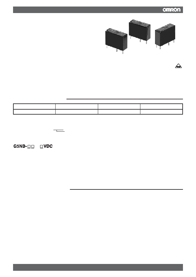
Application Examples
A Miniature Relay with 1-pole 5 A
Switching Capability and 10 kV
Impulse Withstand Voltage
ROHS compliant.
Highly efficient magnetic circuit for high
sensitivity (200 mW).
Compact, slim, yet provides 10 kV impulse
withstand voltage (between coil and contacts).
Standard model conforms to UL, CSA and EN
standards.
Tracking resistance: CTI>250
R
C
Classification
Contact form
Enclosure ratings
Model
Standard
SPST-NO
Flux protection
G5NB-1A
Rated coil voltage
Note: When ordering, add the rated coil voltage to the model number.
Example: G5NB-1A-E 12 VDC
Model Number Legend
1. Number of Poles
3. Rated Coil Voltage
1: 1 pole
5, 12, 18, 24 VDC
2. Contact Form
A: SPST-NO
1 2
3
-E
Water heaters, refrigerators, air conditioners, and small electric
appliances

49
PCB Power Relay ≠ G5NB-E
Rated voltage
5 VDC
12 VDC
18 VDC
24 VDC
Rated current
40.0 mA
16.7 mA
11.1 mA
8.3 mA
Coil resistance
125
720
1,620
2,880
Must operate voltage
75% max. of rated voltage
Must release voltage
10% min. of rated voltage
Max. voltage
170% of rated voltage (at 23∞C)
Power consumption
Approx. 200 mW
Note: The rated current and coil resistance are measured at a coil temperature of 23∞C with a tolerance of ±10%.
The operating characteristics are measured at a coil temperature of 23∞C.
The "Max. voltage" is the maximum voltage that can be applied to the relay coil.
Specifications
Coil Ratings
Contact Ratings
Load
Resistive load (cos
= 1)
Rated load
5 A at 250 VAC, 3 A at 30 VDC
Max. switching voltage
250 VAC, 30 VDC
Max. switching current
5 A
Max. switching power
1250 VA, 90 W
Failure rate (reference value)
10 mA at 5 VDC
Note: P level:
60 = 0.1 x 10
-6
/operation (with an operating frequency of 120 operations/min)
Characteristics
Contact resistance (See note 2.)
100 m max.
Operate time
10 ms max.
Release time
10 ms max.
Insulation resistance (See note 3.)
1,000 M min. (at 500 VDC)
Dielectric strength
4,000 VAC, 50/60 Hz for 1 min between coil and contacts
750 VAC, 50/60 Hz for 1 min between contacts of same polarity
Impulse withstand voltage
10,000 V (1.2 x 50 ms) between coil and contacts
Vibration resistance
Destruction: 10 to 55 to 10 Hz, 0.75-mm single amplitude (1.5-mm double amplitude)
Malfunction: 10 to 55 to 10 Hz, 0.75-mm single amplitude (1.5-mm double amplitude)
Shock resistance
Destruction: 1,000 m/s
2
Malfunction: 100 m/s
2
Endurance
Mechanical: 5,000,000 operations min.
Electrical: 100,000 operations min (5 A at 250 VAC), 200,000 operations min. (3 A at 30 VDC)
Failure rate P level (reference value) 5 VDC, 10 mA
(See note 4.)
Ambient temperature
Operating: -40∞C to 85∞C (with no icing or condensation)
Ambient humidity
Operating: 5% to 85%
Weight
Approx. 4 g
Note: 1. The data shown above are initial value.
2. Measurement conditions: 5 VDC, 1 A, voltage drop method.
3. Measurement conditions: Measured at the same points as the dielectric strength using a 500-VDC ohmmeter.
4. This value is for a switching frequency of 120 operations/minute.
Power Relays

50
PCB Power Relay ≠ G5NB-E
Approved Standards
UL508 (File No. 41515)
Coil ratings
Contact ratings
5 to 24 VDC
5 A, 30 VDC (resistive)
5 A, 125 VAC (resistive)
5 A, 250 VAC (general use)
CSA C22.2 (No. 0, No. 1, No. 14) (File No. LR31928)
Actual Load Life (Reference Values)
Coil ratings
Contact ratings
5 to 24 VDC
5 A, 30 VDC (resistive)
5 A, 125 VAC (resistive)
5 A, 250 VAC (general use)
EN 61810-1 (VDE Reg No 137575)
Coil ratings
Contact ratings
5 to 24VDC
5 A, 30 VDC (resistive)
5 A, 250 VAC (general use)
1. 120-VAC motor and lamp load (2.5-A surge and 0.5-A normal): 250,000 operations min.(at 23∞C)
2. 160-VDC valve load (with varistor) (0.24-A): 250,000 operations min.(at 23∞C)
51
PCB Power Relay ≠ G5NB-E
ALL DIMENSIONS SHOWN ARE IN MILLIMETERS.
To convert millimeters into inches, multiply by 0.03937. To convert grams into ounces, multiply by 0.03527.
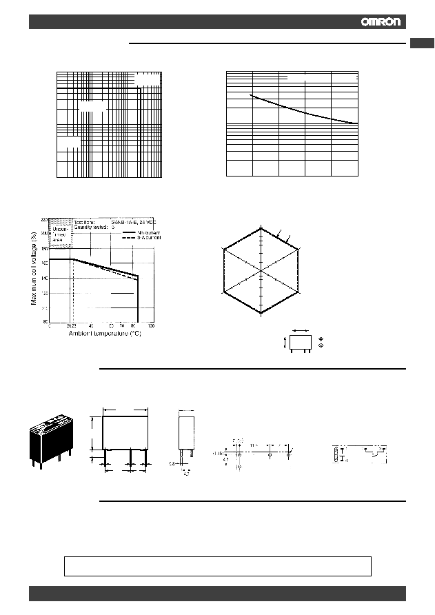
Correct Use
Contact voltage (V)
10
1
10
30
100
250
1,000
DC resistive
load
AC resistive
load
Contact
resistance
Maximum Switching Capacity
Contact current (A)
100
50
30
10
5
3
1
0
1
2
3
4
250 VAC, 30 VDC resistive load
Endurance
Contact current (A)
No. of operations (x 10
4
)
5
3
1
0.1
Ambient Temperature vs. Maximum Coil Voltage
Maximum coil voltage (%)
Ambient temperature (
∞
C)
Test item:
G5NB-1A-E, 24 VDC
Quantity tested: 5
No current
3-A current
Z
Z
Z'
Z'
Shock direction
Unit: m/s
2
Y
Y
Y'
Y'
X
X
X'
X'
1,000
1,000
1,000
1,000
1,000
1,000
Excited
Not excited
700
125
Malfunctioning Shock
G5NB-1A
Quantity Tested: 5 units
Test Method: Shock was applied 3
times in 6 directions along 3 axes
and the level at which shock caused
malfunction was measured.
Rating: 100 m/s
2
Uncon-
firmed
area
Precautions
HANDLING
The enclosure rating of the G5NB is for flux protection. Do not use
immersion-cleaning.
Dimensions
Note: All units are in millimeters unless otherwise indicated.
PCB Mounting Holes
(Bottom View)
Tolerance:
±
0.1 mm
Terminal Arrangement/
Internal Connections
(Bottom View)
7.2 max.
(7.0)*
Four, 1.1 dia.
(No coil polarity)
*Average value
15. 3 max.
(15.0)*
3.4
0.4
11.5
7
0.27
0.33
20.5 max.
(20.4)*
G5NB-1A-E
Engineering Data
Power Relays