Document Outline
- PCB Relay G6C
- Ordering Information
- Accessories (Order Separately)
- Specifications
- Coil Ratings
- Contact Ratings
- Characteristics
- Approved Standards
- Engineering Data
- Dimensions
1
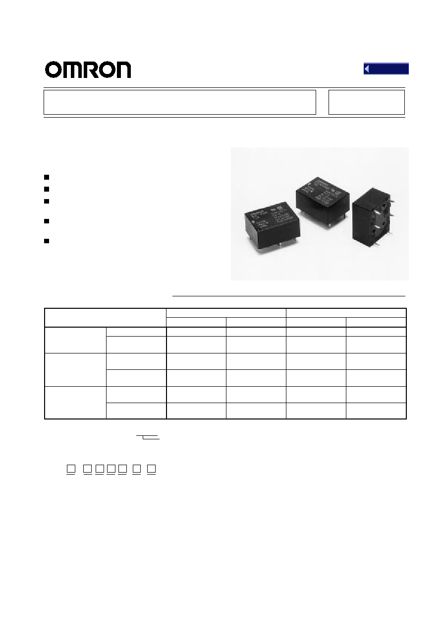
PCB Relay G6C
SPST-NO Type Breaks 10-A Loads;
SPST-NO + SPST-NC Type
Breaks 8-A Load
Compact: 20 x 15 x 10 mm (L x W x H).
Low power consumption: 200 mW.
Flux protection or plastic-sealed construction
available.
Unique moving loop armature reduces relay size,
magnetic interference, and contact bounce.
Single- and double-winding latching types also
available
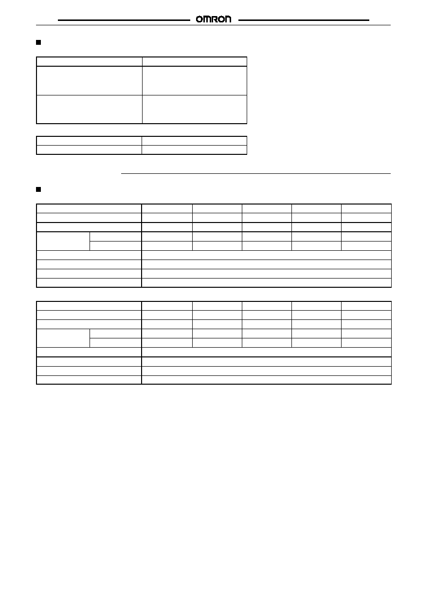
Ordering Information
Classification
Straight PCB
Self-clinching PCB
Flux protection
Plastic-sealed
Flux protection
Plastic-sealed
Single-side stable
SPST-NO
G6C-1117P-US
G6C-1114P-US
G6C-1117C-US
G6C-1114C-US
SPST-NO +
SPST-NC
G6C-2117P-US
G6C-2114P-US
G6C-2117C-US
G6C-2114C-US
Single-winding
latching
SPST-NO
G6CU-1117P-US
G6CU-1114P-US
G6CU-1117C-US
G6CU-1114C-US
SPST-NO +
SPST-NC
G6CU-2117P-US
G6CU-2114P-US
G6CU-2117C-US
G6CU-2114C-US
Double-winding
latching
SPST-NO
G6CK-1117P-US
G6CK-1114P-US
G6CK-1117C-US
G6CK-1114C-US
SPST-NO +
SPST-NC
G6CK-2117P-US
G6CK-2114P-US
G6CK-2117C-US
G6CK-2114C-US
Rated coil voltage
Note: When ordering, add the rated coil voltage to the model number.
Example: G6C-1117P-US 12 VDC
Model Number Legend:
G6C - - VDC
1
2
3
4
5
1.
Relay Function
None:Single-side stable
U: Single-winding latching
K: Double-winding latching
2.
Contact Form
11: SPST-NO
21: SPST-NO + SPST-NC
3.
Contact Type
1: Single button
4.
Enclosure Ratings
7: Flux protection
4: Plastic-sealed
5.
Terminals
P: Straight PCB
C: Self-clinching PCB
6.
Approved Standards
US: UL/CSA certified
7.
Rated Coil Voltage
3, 5, 6, 12, 24 VDC
6
7
Back
G6C
G6C
2
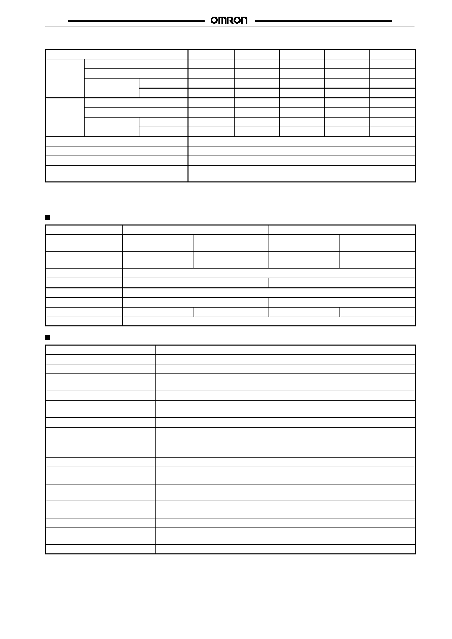
Accessories (Order Separately)
Back Connecting Sockets
Applicable relay
Back connecting socket*
G6C(U)-1114P-US
G6C(U)-1117P-US
G6C(U)-2114P-US
G6C(U)-2117P-US
P6C-06P
G6CK-1114P-US
G6CK-1117P-US
G6CK-2114P-US
G6CK-2117P-US
P6C-08P
*Not applicable to the self-clinching versions.
Removal Tool
P6B-Y1
Hold-down Clips
P6B-C2
Specifications
Coil Ratings
Single-side Stable Type
Rated voltage
3 VDC
5 VDC
6 VDC
12 VDC
24 VDC
Rated current
67 mA
40 mA
33.3 mA
16.7 mA
8.3 mA
Coil resistance
45
125
180
720
2,880
Coil inductance
Armature OFF
0.078
0.22
0.36
1.32
4.96
(H) (ref. value)
Armature ON
0.067
0.18
0.29
1.13
4.19
Must operate voltage
70% max. of rated voltage
Must release voltage
10% min. of rated voltage
Max. voltage
130% of rated voltage
Power consumption
Approx. 200 mW
Single-winding Latching Type
Rated voltage
3 VDC
5 VDC
6 VDC
12 VDC
24 VDC
Rated current
67 mA
40 mA
33.3 mA
16.7 mA
8.3 mA
Coil resistance
45
125
180
720
2,880
Coil inductance
Armature OFF
0.09
0.25
0.36
1.75
5.83
(H) (ref. value)
Armature ON
0.06
0.20
0.24
1.17
3.84
Must operate voltage
70% max. of rated voltage
Must release voltage
70% min. of rated voltage
Max. voltage
130% of rated voltage
Power consumption
Approx. 200 mW
G6C
G6C
3
Double-winding Latching Type
Rated voltage
3 VDC
5 VDC
6 VDC
12 VDC
24 VDC
Set coil
Rated current
93.5 mA
56.0 mA
46.7 mA
23.3 mA
11.7 mA
Coil resistance
32.1
89.3
129
514
2,056
Coil inductance
Armature OFF
0.03
0.07
0.10
0.37
1.56
(H) (ref. value)
Armature ON
0.02
0.06
0.08
0.32
1.18
Reset coil
Rated current
93.5 mA
56.0 mA
46.7 mA
23.3 mA
11.7 mA
Coil resistance
32.1
89.3
129
514
2,056
Coil inductance
Armature OFF
0.03
0.08
0.12
0.47
1.46
(H) (ref. value)
Armature ON
0.02
0.07
0.10
0.38
1.13
Must set voltage
70% max. of rated voltage
Must reset voltage
70% min. of rated voltage
Max. voltage
130% of rated voltage
Power consumption
Set coil:
Approx. 280 mW
Reset coil: Approx. 280 mW
Note:
1. The rated current and coil resistance are measured at a coil temperature of 23
�
C with a tolerance of
�
10%.
2. Operating characteristics are measured at a coil temperature of 23
�
C.
3. The minimum pulse width of the set and reset voltage is 20 ms.
Contact Ratings
Item
SPST-NO
SPST-NO+SPST-NC
Load
Resistive load
(cos
= 1)
Inductive load
(cos
= 0.4; L/R = 7 ms)
Resistive load
(cos
= 1)
Inductive load
(cos
= 0.4; L/R = 7 ms)
Rated load
10 A at 250 VAC;
10A at 30 VDC
5 A at 250 VAC;
5 A at 30 VDC
8 A at 250 VAC;
8A at 30 VDC
3.5 A at 250 VAC;
3.5 A at 30 VDC
Contact material
AgCdO
Rated carry current
10 A
8 A
Max. switching voltage
380 VAC, 125 VDC (the case of latching 250 VAC, 125 VDC)
Max. switching current
10 A
8 A
Max. switching capacity
2,500 VA, 300 W
1,250 VA, 220 W
2,000 VA, 240 W
875 VA, 170 W
Min. permissible load
10 mA at 5 VDC
Characteristics
Contact resistance
30 m
max.
Operate (set) time
10 ms max. (mean value: approx. 5 ms)
Release (reset) time
10 ms max. (mean value: approx. 2 ms; latching types: mean value: approx. 5 ms)
Bounce time
Operate: 5 ms max.
Release: 5 ms max.
Min. set/reset signal width
Latching type: 20 ms (at 23
�
C)
Max. switching frequency
Mechanical: 18,000 operations/hr
Electrical:
1,800 operations/hr (under rated load)
Insulation resistance
1,000 M
min. (at 500 VDC, at 250 VDC between set coil and reset coil)
Dielectric strength
2,000 VAC, 50/60 Hz for 1 min between coil and contacts
2,000 VAC, 50/60 Hz for 1 min between contacts of different polarity
1,000 VAC, 50/60 Hz for 1 min between contacts of same polarity
250 VAC, 50/60 Hz for 1 min between set and reset coils
Impulse withstand voltage
6.000 V, 1.2 x 50
�
s (between coil and contacts) (latching types: 4500 V, 1.2
50
�
s)
Vibration resistance
Destruction: 10 to 55 Hz, 1.5-mm double amplitude
Malfunction: 10 to 55 Hz, 1.5-mm double amplitude
Shock resistance
Destruction: 1,000 m/s
2
(approx. 100G)
Malfunction: 100 m/s
2
(approx. 10G)
Ambient temperature
Operating: �25
�
C to 70
�
C (with no icing)
Storage:
�25
�
C to 70
�
C (with no icing)
Ambient humidity
Operating: 35% to 85%
Life expectancy
Mechanical: 50,000,000 operations min. (at 18,000 operations/hr)
Electrical:
100,000 operations min. (at 1,800 operations/hr)
Weight
Approx. 5.6 g
G6C
G6C
4
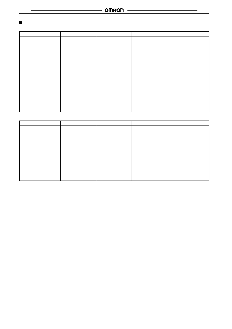
Approved Standards
UL508 (File No. E41643)
Model
Contact form
Coil rating
Contact rating
G6C-1114P-US
G6C-1114C-US
G6C-1117P-US
G6C-1117C-US
SPST-NO
3 to 60 VDC
10 A, 250 VAC (general use)
10 A, 30 VDC (resistive load)
1/6 hp, 125 VAC
1/4 hp, 125 VAC
1/4 hp, 250 VAC
1/3 hp, 250 VAC
TV-5
600 W, 120 VAC (tungsten)
530 VA, 20 to 265 VAC, 2 A max. (pilot duty)
43.2 VA, 30 VDC (pilot duty)
12LRA, 2.2FLA, 30 VDC (30,000 cycle)
G6C-2114P-US
G6C-2114C-US
G6C-2117P-US
G6C-2117C-US
SPST-NO + SPST-NC
8 A, 250 VAC (general use)
8 A, 30 VDC (resistive load)
1/6 hp, 125 VAC
1/4 hp, 125 VAC
1/4 hp, 250 VAC
TV-5
600 W, 120 VAC (tungsten)
530 VA, 20 to 265 VAC, 2 A max. (pilot duty)
43.2 VA, 30 VDC (pilot duty)
12LRA, 2.2FLA, 30 VDC (30,000 cycle)
CSA C22.2 No.14 (File No. LR31928)
Model
Contact form
Coil rating
Contact rating
G6C-1114P-US
G6C-1114C-US
G6C-1117P-US
G6C-1117C-US
SPST-NO
3 to 60 VDC
10 A, 250 VAC (general use)
10 A, 30 VDC (resistive load)
1/6 hp, 125 VAC
1/4 hp, 125 VAC
1/4 hp, 250 VAC
1/3 hp, 250 VAC
TV-5
600 W, 120 VAC (tungsten)
G6C-2114P-US
G6C-2114C-US
G6C-2117P-US
G6C-2117C-US
SPST-NO + SPST-NC
3 to 60 VDC
8 A, 250 VAC (general use)
8 A, 30 VDC (resistive load)
1/6 hp, 125 VAC
1/4 hp, 125 VAC
1/4 hp, 250 VAC
TV-5
600 W, 120 VAC (tungsten)
G6C
G6C
5
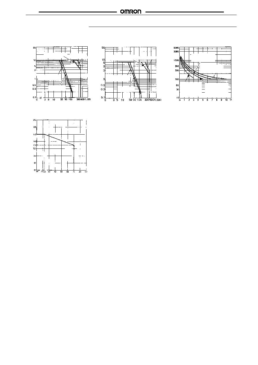
Engineering Data
Max. Switching Capacity
SPST-NO
Switching voltage (V)
SPST-NO + SPST-NC
Life Expectancy
Life expectancy (x10 operations)
3
Switching current (A)
Switching current (A)
Switching voltage (V)
Switching current (A)
AC resistive
load
AC inductive load
(cos
= 0.4)
DC resistive
load
DC inductive load
(L/R = 7 ms)
AC resistive load
AC inductive load
(cos
= 0.4)
DC inductive load
(L/R = 7 ms)
G6C-2114P-US
250-VAC resistive
30-VDC resistive
G6C-1114P-US
250-VAC resistive
30-VDC resistive
G6C-2114P-US
250-VAC induc-
tive (cos
= 0.4)
30-VDC induc-
tive (L/R = 7 ms)
G6C-1114P-US
250-VAC induc-
tive (cos
= 0.4)
30-VDC inductive
(L/R = 7 ms)
DC resistive
load
Ambient Temperature vs.
Maximum Voltage
Maximum voltage (%)
Ambient temperature (
�
C)
G6C
G6C
6
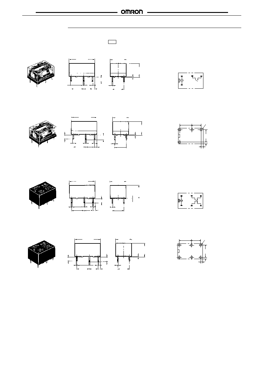
Dimensions
Note:
1. All units are in millimeters unless otherwise indicated.
2. Orientation mark is indicated as follows:
Terminal Arrangement/Internal
Connections (Bottom View)
Mounting Holes
(Bottom View)
G6C-
j
117P-US
G6C-
j
117C-US
G6C-1117P-US, G6C-1117C-US
G6C-1114P-US, G6C-1114C-US
Tolerance:
�
0.1
*Average value
*Average value
(19.9)*
20 max.
3.5
0.8
0.8
0.6
10.16
7.62
1.11
(14.9)*
15 max.
(9.9)*
10 max.
0.3
10.16
0.4
(19.9)*
20 max.
(14.9)*
15 max.
0.8
0.8
0.6
0.4
10.16
7.62
1.11
10.16
0.3
(9.9)*
10 max.
3.5
3.2
10.16
(2.4)
10.16
7.62
(1.1)
Four, 1.1-dia. holes
8
1
3
4
+
�
G6C-2117P-US, G6C-2117C-US
G6C-2114P-US, G6C-2114C-US
G6C-
j
114P-US
G6C-
j
114C-US
*Average value
*Average value
(19.9)*
20 max.
(14.9)*
15 max.
(9.9)*
10 max.
0.3
3.5
0.8
0.8
0.6
0.4
10.16
1.11
7.62
10.16
(19.9)*
20 max.
(14.9)*
15 max.
(9.9)*
10 max.
0.3
3.5
0.8
0.8
0.6
0.4
10.16
1.11
7.62
10.16
3.2
Terminal Arrangement/Internal
Connections (Bottom View)
Mounting Holes
(Bottom View)
Tolerance:
�
0.1
10.16
(2.4)
10.16
7.62
(1.1)
Six, 1.1-dia. holes
8
1
3
4
+
�
6
5
G6C
G6C
7
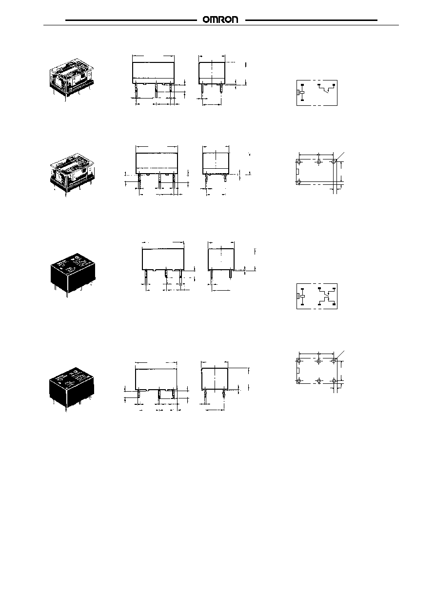
Terminal Arrangement/Internal
Connections (Bottom View)
Mounting Holes
(Bottom View)
G6CU-
j
117P-US
G6CU-1117P-US, G6CU-1117C-US
G6CU-1114P-US, G6CU-1114C-US
*Average value
*Average value
G6CU-
j
117C-US
(19.9)*
20 max.
(14.9)*
15 max.
(9.9)*
10 max.
0.3
3.5
0.8
0.8
0.6
0.4
10.16
1.11
7.62
10.16
(19.9)*
20 max.
(14.9)*
15 max.
(9.9)*
10 max.
0.3
3.5
0.8
0.8
0.6
0.4
10.16
1.11
7.62
10.16
10.16
7.62
10.16
(1.1)
(2.4)
Four, 1.1-dia holes
8
1
3
4
+
�
0
G6CU-2117P-US, G6CU-2117C-US
G6CU-2114P-US, G6CU-2114C-US
G6CU-
j
114P-US
G6CU-
j
114C-US
*Average value
*Average value
(19.9)*
20 max.
(14.9)*
15 max.
(9.9)*
10 max.
0.3
3.5
0.8
0.8
0.6
0.4
10.16
1.11
7.62
10.16
3.2
(19.9)*
20 max.
(14.9)*
15 max.
(9.9)*
10 max.
0.3
3.5
0.8
0.8
0.6
0.4
10.16
1.11
7.62
10.16
3.2
Terminal Arrangement/Internal
Connections (Bottom View)
Mounting Holes
(Bottom View)
10.16
7.62
10.16
(1.1)
(2.4)
Six, 1.1-dia holes
8
1
3
4
+
�
6
5
S
�
+
R
G6C
G6C
8
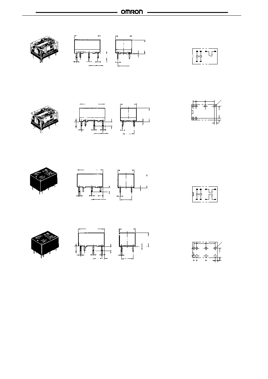
G6CK-
j
117P-US
G6CK-1117P-US, G6CK-1117C-US
G6CK-1114P-US, G6CK-1114C-US
*Average value
(19.9)*
20 max.
(14.9)*
15 max.
(9.9)*
10 max.
0.3
3.5
0.8
0.8
0.6
0.4
1.11
7.62
10.16
Terminal Arrangement/Internal
Connections (Bottom View)
Mounting Holes
(Bottom View)
�
10.16
(2.4)
7.62
7.62
2.5
(1.1)
Four, 1.1-dia
holes
G6CK-
j
117C-US
*Average value
(19.9)*
20 max.
(14.9)*
15 max.
(9.9)*
10 max.
0.3
3.5
0.8
0.8
0.4
1.11
7.62
10.16
1 2
3
4
7
8
S
R
+
�
+
�
G6CK-2117P-US, G6CK-2117C-US
G6CK-2114P-US, G6CK-2114C-US
G6CK-
j
114P-US
G6CK-
j
114C-US
*Average value
*Average value
Terminal Arrangement/Internal
Connections (Bottom View)
Mounting Holes
(Bottom View)
(19.9)*
20 max.
(14.9)*
15 max.
(9.9)*
10 max.
0.3
3.5
0.8
0.8
0.6
0.4
1.11
7.62
10.16
(19.9)*
20 max.
(14.9)*
15 max.
(9.9)*
10 max.
0.3
3.5
0.8
0.8
0.6
0.4
1.11
7.62
10.16
10.16
(2.4)
7.62
7.62
2.5
(1.1)
Six., 1.1-dia.
holes
1 2
3
4
5
6
7
8
S
R
+
�
+
�
3.2
3.2
G6C
G6C
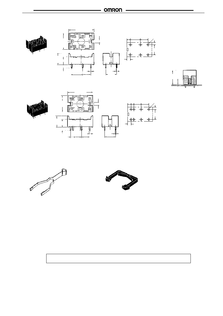
9
Mounting Holes (Bottom View)
Mounting Height of Relay
with Connecting Socket
P6C-08P
Note: Rated current of socket max. 5 A
Back Connecting Sockets
P6C-06P
(23)*
23.2 max.
(14.9)
15 max.
3.1
(10.6)*
10.8 max. 7.5
3.5
0.8
0.4
10.16
7.62
10.16
17 mm
max.
7.5 mm
max.
7.62
10.16
10.16
(2.61)
(2.4)
(2.61)
Six, 1.1-dia holes
7.62
10.16
7.62
2.61
(2.4)
(2.61)
Eight, 1.1-dia holes
2.54
Removal Tool
P6B-Y1
Hold-down Clips
P6B-C2
(23)*
23.2 max.
(14.9)
15 max.
3.1
(10.6)*
10.8 max. 7.5
3.5
2.54
0.8
0.4
7.62
7.62
10.16
*Average value
*Average value
Mounting Holes (Bottom View)
ALL DIMENSIONS SHOWN ARE IN MILLIMETERS.
To convert millimeters into inches, multiply by 0.03937. To convert grams into ounces, multiply by 0.03527.
Cat. No. K18-E1-4C