Document Outline
- PCB Relay G6D
- Ordering Information
- Accessories (Order Separately)
- Specifications
- Coil Ratings
- Contact Ratings
- Characteristics
- Approved Standards
- Engineering Data
- Dimensions
- Precautions

1
PCB Relay G6D
Slim, Miniature Relay (17.5 x 6.5 x 12.5
(L x W x H)), Capable of Relaying
Programmable Controller and
Temperature Controller Outputs
Reduced bottom area (45% smaller than the G6B's
bottom area) ideal for high-density mounting.
Switches 5 A at 250 VAC/30 VDC.
Allows 300,000 operations with a 2-A load at
250 VAC or 30 VDC.
Actual load switching capability equals the G6B's
capability.
Washable construction.
Ordering Information
Contact form
Model
SPST-NO
G6D-1A
Rated coil voltage
Note: When ordering, add the rated coil voltage to the model number.
Example: G6D-1A 12 VDC
Classification
Contact form: SPST-NO
Enclosure: Plastic sealed
Terminal: PCB terminal
Model Number Legend:
G6D - VDC
1
2
1.
Number of Poles
1: 1 pole
2.
Contact Form
A: SPST-NO
3.
Rated Coil Voltage
5, 12, 24 VDC
3
Accessories (Order Separately)
Connecting Socket
P6D-04P
Back

G6D
G6D
2
Specifications
Coil Ratings
Rated voltage
5 VDC
12 VDC
24 VDC
Rated current
40 mA
16.7 mA
8.3 mA
Coil resistance
125
720
2,880
Must operate voltage
70% max. of rated voltage
Must release voltage
10% min. of rated voltage
Max. voltage
130% of rated voltage
Power consumption
Approx. 200 mW
Note: The must operate voltage is 75% or less of the rated voltage if the relay is mounted upside down.
Contact Ratings
Load
Resistive load (cos
= 1)
Rated load
5 A at 250 VAC, 5 A at 30 VDC
Rated carry current
5 A
Max. switching voltage
250 VAC, 30 VDC
Max. switching current
5 A
Max. switching capacity
1,250 VA, 150 W
Min. permissible load
10 mA at 5 VDC
Note: P level:
60
= 0.1 x 10
-6
/operation
Characteristics
Contact resistance
100 m
max.
Operating time
10 ms max.
Release time
5 ms max.
Insulation resistance
1,000 M
min. (at 500 VDC)
Dielectric strength
3,000 VAC, 50/60 Hz for 1 min between coil and contacts
750 VAC, 50/60 Hz for 1 min between contacts of same polarity
Impulse withstand voltage
6,000 V 1.2 x 50
µ
s (between coil and contacts)
Vibration resistance
Destruction: 10 to 55 Hz, 1.5-mm double amplitude
Malfunction: 10 to 55 Hz, 1.5-mm double amplitude
Shock resistance
Destruction: 1,000 m/s
2
(approx. 100G)
Malfunction: 100 m/s
2
(approx. 10G)
Life expectancy
Mechanical: 20,000,000 operations min. (at 18,000 operations/hr)
Electrical: 100,000 operations min. (5 A at 250 VAC/30 VDC, resistive load)
300,000 operations min. (2 A at 250 VAC/30 VDC, resistive load)
Ambient temperature
Operating: ≠25
∞
C to 70
∞
C (with no icing)
Storage: ≠25
_
C to 70
_
C (with no icing)
Ambient humidity
Operating: 35% to 85%
Storage: 35% to 85%
Weight
Approx. 3 g
Approved Standards
UL508 (File No. E41515)/CSA C22.2 No.14 (File No. LR31928)
Model
Coil ratings
Contact ratings
G6D-1A
5 to 24 VDC
5 A, 250 VAC
5 A, 30 VDC
G6D
G6D
3
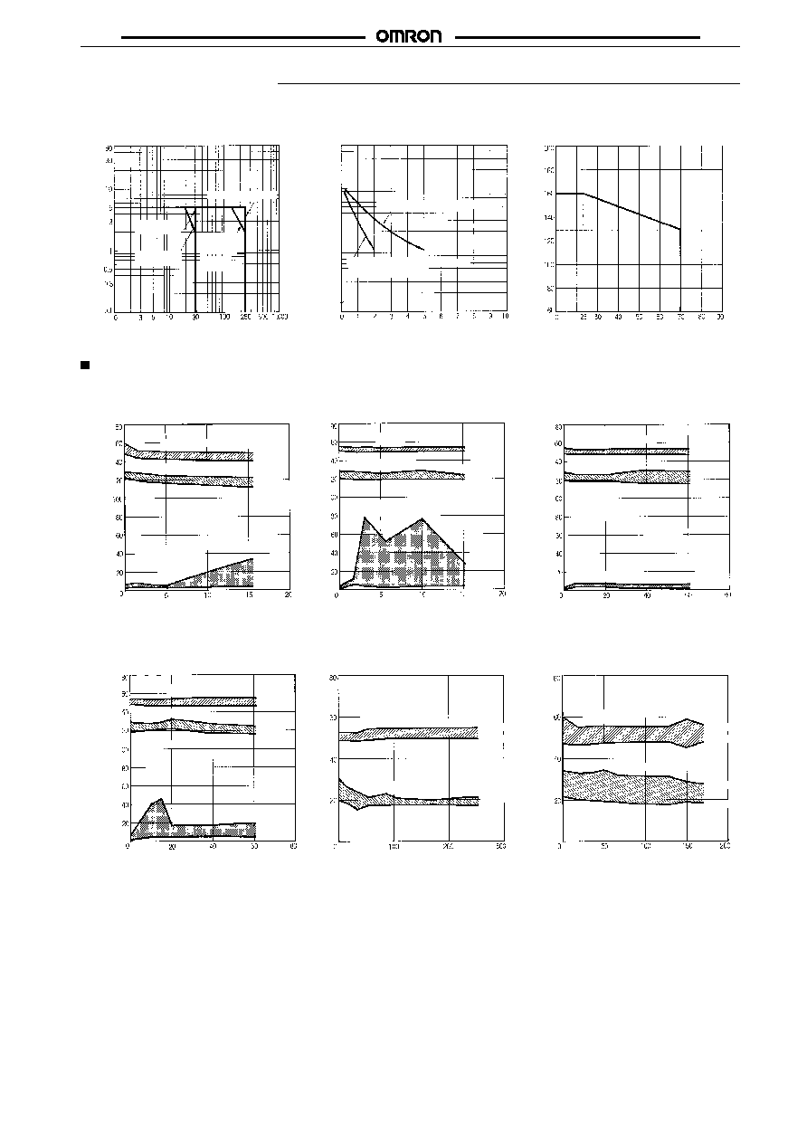
Engineering Data
Max. Switching Capacity Ambient Temperature vs.
Maximum Voltage
Life Expectancy
Switching current (A)
Switching voltage (V) Switching current (A)
Life expectancy (x10 operations)
3
Ambient temperature (
∞
C)
Maximum voltage (%)
AC resistive load
AC in-
ductive
load
DC resistive
load
DC inductive
load
5000
3000
1000
500
300
100
50
30
250-VAC/30-VDC resistive load
250-VAC/30 VDC inductive load
(cos
= 1/ L/R = 7 ms)
cos
=
0.4
Reference Data
Electrical Life Expectancy
5 A at 250 VAC, cos
= 1
Number of operations (x 10
4
)
5 A at 30 VDC, Resistive Load 2 A at 30 VDC, Resistive Load
Operating voltage
Release voltage
Contact resistance
Contact
resistance
Operating voltage
Release voltage
Operating voltage
Release voltage
Contact resistance
Number of operations (x 10
4
) Number of operations (x 10
4
)
Contact resistance
Operating voltage
Release voltage
Operating voltage
Release voltage
Operating voltage
Release voltage
Electrical Life Expectancy
2 A at 250 VAC, cos
= 1
Actual Load Test Data
With OMRON's H3BA Timer
(5 mA at 200 VAC)
With OMRON's MA415A Contacter
(40 mA at 200 VAC)
Number of operations (x 10
4
) Number of operations (x 10
4
) Number of operations (x 10
4
)
Operating/release voltage (%)
Operating/release voltage (%)
Max.
Min.
Max.
Min.
Max.
Min.
Max.
Min.
Max.
Min.
Max.
Min.
Max.
Min.
Max.
Min.
Max.
Min.
Max.
Min.
Max.
Min.
Max.
Min.
Max.
Min.
Max.
Min.
Max.
Min.
Max.
Min.
/Operating/release
voltage (%)
Contact resistance
(m )
W
/Operating/release
voltage (%)
Contact resistance
(m )
W
/Operating/release
voltage (%)
Contact resistance
(m )
W
/Operating/release
voltage (%)
Contact resistance
(m )
W

G6D
G6D
4
Dimensions
Note: 1. All units are in millimeters unless otherwise indicated.
2. Orientation marks are indicated as follows:
G6D-1A
Terminal Arrangement/
Internal Connections
(Bottom View)
Mounting Holes
(Bottom View)
Tolerance:
±
0.1
P6D-04P Socket
1
13
5
7
(1.13)
(0.71)
2.54
2.54
0.5
15.24
5.08
12.5 max.
17.5 max.
6.5
2.54
3.6
10.8
0.65
2.54
0.3
3.5
5.08
7.62.
0.8
5.08
0.5
0.3
5.08
76.2
19.7 max.
6.9 max.
6
±
0.1
(2.18)
(0.86)
2.54
2.54
15.24
5.08
Mounting Holes
(Bottom View)
Tolerance:
±
0.1
Four, 1.1-dia.
holes
Four, 1.1-dia.
holes
(17.3)*
max.
(6.4)*
(12.4)*
*Average value
*Average value
(6.7)*
(19.5)*
Precautions
More than two relays can be closely mounted right side up as shown
in the following illustration.
Current flow:
5 A max.
6.5 mm
More than two relays can be closely mounted upside down as
shown in the following illustration.
7.62 mm in the
upside-down
direction
1.12 mm
Current flow:
2 A max.
Note: The space between each relay required for heat radiation
may vary with operating conditions. Contact your OMRON
representative for details.
Socket Mounting Height
18.5 mm max.
When mounting the relay, insert it into the socket as vertically as
possible so that the relay terminals contact securely with the contact
pins on the socket.
The P6D is flux-resistive. Do not wash the P6D with water.
Dismount the relay from the socket before soldering the socket to a
PCB.
ALL DIMENSIONS SHOWN ARE IN MILLIMETERS.
To convert millimeters into inches, multiply by 0.03937. To convert grams into ounces, multiply by 0.03527.
Cat. No. K84-E1-1B