Document Outline
- PCB Relay G6E
- Ordering Information
- Specifications
- Coil Ratings
- Contact Ratings
- Characteristics
- Approved Standards
- Engineering Data
- Dimensions
1
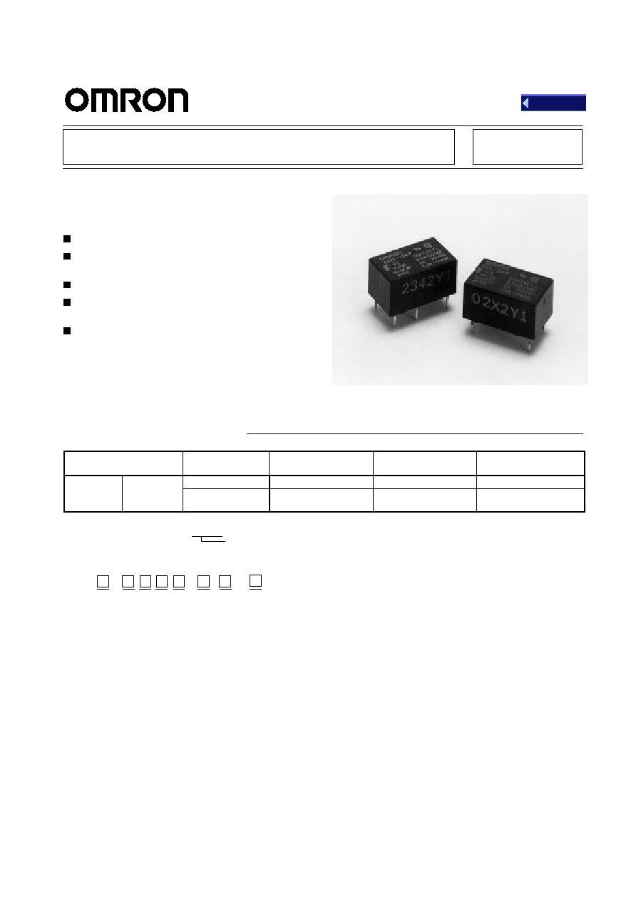
PCB Relay G6E
Subminiature, Sensitive SPDT Signal
Switching Relay
High sensitivity: 98 mW pickup coil power.
Impulse withstand voltage meets FCC Part 68
requirements.
Plastic-sealed construction.
Unique moving loop armature reduces relay size,
magnetic interference, and contact bounce time.
Single- and double-winding latching types also
available.
Ordering Information
Contact form
Terminal
Single-side stable
Single-winding
latching
Double-winding
latching
SPDT
Bifurcated
b
Straight terminal
G6E-134P-US
G6EU-134P-US
G6EK-134P-US
u ca ed
crossbar
Self-clinching
terminal
G6E-134C-US
G6EU-134C-US
G6EK-134C-US
Rated coil voltage
Note: When ordering, add the rated coil voltage to the model number.
Example: G6E-134P-US 12 VDC
Model Number Legend:
1.
Relay Function
None:Single-side stable
U: Single-winding latching
K: Double-winding latching
2.
Contact Form
1: SPDT
3.
Contact Type
3: Bifurcated crossbar
Ag (Au-clad) contact
9: Bifurcated crossbar
AgNi (Au-clad) contact
4.
Enclosure Rating
4: Plastic-sealed
5.
Terminals
P: Straight PCB
C: Curved tail
6.
Approved Standards
US: UL, CSA certified
7.
Special Function
U: For ultrasonically cleanable
8.
Rated Coil Voltage
3, 5, 6, 9, 12, 24, 48 VDC
G6E - - - VDC
1
2
3
4
5
6
7
8
Back

G6E
G6E
2
Specifications
Coil Ratings
Single-side Stable, Bifurcated Crossbar Contact Type
Rated voltage
3 VDC
5 VDC
6 VDC
9 VDC
12 VDC
24 VDC
48 VDC
Rated current
66.7 mA
40 mA
33.3 mA
22.2 mA
16.7 mA
8.3 mA
8.3 mA
Coil resistance
45
125
180
405
720
2,880
5,760
Coil inductance
Armature OFF
0.08
0.18
0.31
0.62
1.20
4.70
5.35
(H) (ref. value)
Armature ON
0.06
0.17
0.24
0.50
0.99
3.90
5.12
Must operate voltage
70% max. of rated voltage
Must release voltage
10% min. of rated voltage
Max. voltage
155% of rated voltage at 50
∞
C, 130% at
∞
70C
140% of rated voltage at
50
∞
C, 115% at 70
∞
C
Power consumption
Approx. 200 mW
Approx. 400 mW
Single-winding Latching, Bifurcated Crossbar Contact Type
Rated voltage
3 VDC
5 VDC
6 VDC
9 VDC
12 VDC
24 VDC
Rated current
66.7 mA
40 mA
33.3 mA
22.2 mA
16.7 mA
8.3 mA
Coil resistance
45
125
180
405
720
2,880
Coil inductance
Armature OFF
0.05
0.13
0.19
0.45
0.84
3.56
(H) (ref. value)
Armature ON
0.04
0.12
0.17
0.40
0.79
3.10
Must set voltage
70% max. of rated voltage
Must reset voltage
70% max. of rated voltage
Max. voltage
130% of rated voltage at 70
∞
C
Power consumption
Approx. 200 mW
Double-winding Latching, Bifurcated Crossbar Contact Type
Rated voltage
3 VDC
5 VDC
6 VDC
9 VDC
12 VDC
24 VDC
Set coil
Rated current
66.7 mA
40 mA
33.3 mA
22.2 mA
16.7 mA
8.3 mA
Coil resistance
45
125
180
405
720
2,880
Coil inductance
Armature OFF
0.03
0.09
0.12
0.25
0.44
1.66
(H) (ref. value)
Armature ON
0.03
0.08
0.11
0.22
0.41
1.62
Reset coil
Rated current
66.7 mA
40 mA
33.3 mA
22.2 mA
16.7 mA
8.3 mA
Coil resistance
45
125
180
405
720
2,880
Coil inductance
Armature OFF
0.03
0.09
0.12
0.25
0.44
1.66
(H) (ref. value)
Armature ON
0.03
0.08
0.11
0.22
0.41
1.62
Must set voltage
70% max. of rated voltage
Must reset voltage
70% max. of rated voltage
Max. voltage
130% of rated voltage at 70
∞
C
Power consumption
Set coil:
Approx. 200 mW
Reset coil: Approx. 200 mW
Note:
1. The rated current and coil resistance are measured at a coil temperature of 23
∞
C with a tolerance of
±
10%.
2. Operating characteristics are measured at a coil temperature of 23
∞
C.
Contact Ratings
Load
Resistive load (cos
= 1)
Inductive load (cos
= 0.4; L/R = 7 ms)
Rated load
0.4 A at 125 VAC; 2 A at 30 VDC
0.2 A at 125 VAC; 1 A at 30 VDC
Contact material
Ag (Au-clad)
Rated carry current
3 A
Max. switching voltage
250 VAC, 220 VDC
Max. switching current
3 A
3 A
Max. switching capacity
50 VA, 60 W
25 VA, 30 W
Min. permissible load
10
µ
A at 10 mVDC
Note:
P level:
60
= 0.1 x 10
-6
/operation
G6E
G6E
3
Characteristics
Contact resistance
50 m
max.
Operate (set*) time
5 ms max. (mean value: approx. 2.9 ms; 48 VDC type: approx. 2.4 ms)
Release (reset*) time
5 ms max. (mean value: approx. 1.3 ms)
Bounce time
Operate: 3 ms max. (mean value: 0.37 ms)
Release: 3 ms max. (mean value: 1.12 ms)
Max. operating frequency
Mechanical: 36,000 operations/hr
Electrical:
1,800 operations/hr (under rated load)
Insulation resistance
1,000 M
min. (at 500 VDC)
Dielectric withstand voltage
1,500 VAC, 50/60 Hz for 1 min between coil and contacts
1,000 VAC, 50/60 Hz for 1 min between contacts of same polarity
Impulse withstand voltage
1,500 V 10 x 160
µ
s (conforms to FCC Part 68)
Vibration resistance
Destruction: 10 to 55 Hz, 5-mm double amplitude
Malfunction: 10 to 55 Hz, 3.3-mm double amplitude
Shock resistance
Destruction: 1,000 m/s
2
(approx. 100G)
Malfunction: 300 m/s
2
(approx. 30G)
Life expectancy
Mechanical: 100,000,000 operations min. (at 36,000 operations/hr)
Electrical:
100,000 operations min. (0.4 A at 125 VAC resistive load;
0.2 A at 125 VAC inductive load)
500,000 operations min. (2 A at 30 VDC resistive load;
1 A at 30 VDC inductive load)
200,000 operations min. (3 A at 30 VDC resistive load)
Ambient temperature
Operating: ≠40
∞
C to 70
∞
C (with no icing)
Storage:
≠40
∞
C to 70
∞
C (with no icing)
Ambient humidity
35% to 85%
Weight
Approx. 2.7 g
*Minimum set and reset signals width is 7 ms min.
Approved Standards
UL508 (File No. E41515)/CSA C22.2, No.14 (File No. LR31928)
Contact form
Coil ratings
Contact ratings
SPDT
3 to 48 VDC
0.2 A, 250 VAC (general use)
0.6 A, 125 VAC (general use)
2 A, 30 VDC (resistive)
0.6 A, 125 VDC (resistive, Ag contact only)
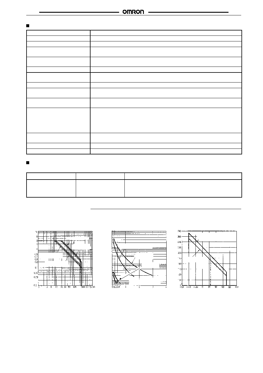
Engineering Data
Max. Switching Capacity
Ambient Temperature vs.
Maximum Voltage
Life Expectancy
Switching current (A)
Switching voltage (V)
Switching current (A)
Life expectancy (x10 operations)
3
Ambient temperature (
∞
)
Maximum voltage (%)
DC resistive load
AC resis-
tive load
DC inductive load
(L/R = 7 ms)
AC inductive load
(cos
= 0.4)
30-VDC inductive load
(L/R = 7 ms)
30-VDC re-
sistive load
125-VAC re-
sistive load
125-VAC inductive load
(cos
= 0.4)
G6E-134P-US,
G6EK-134P-US,
G6EU-134P-US
G6E-134P-US
Only at 48VDC
100,000
50,000
3,000
10,000
5,000
3,000
1,000
500
300
100
50

G6E
G6E
4
Dimensions
Note:
1. All units are in millimeters unless otherwise indicated.
2. Orientation marks are indicated as follows:
Terminal Arrangement/
Internal Connections
(Bottom View)
Mounting Holes
(Bottom View)
Tolerance:
±
0.1
G6E-134P-US,
G6E-194P-US
G6E-134C-US,
G6E-194C-US
(15.9) *
16 max.
(9.9) *
10
max.
(7.9) *
8 max.
0.3
3.5
7.62
0.25
7.62
5.08
1.6
0.6
0.3
7.62
0.25
7.62
5.08
1.6
0.6
(15.9) *
16 max.
(9.9) *
10
max.
2.86
3.16
1 +
≠ 6
12
10
7
5.08
7.62
7.62
(1.65)
Five, 1.0-dia. holes
(1.19)
*Average value
(7.9) *
8 max.
G6EU-134P-US,
G6EU-194P-US
G6EU-134C-US,
G6EU-194C-US
Terminal Arrangement/
Internal Connections
(Bottom View)
Mounting Holes
(Bottom View)
Tolerance:
±
0.1
0.3
7.62
0.25
7.62
5.08
1.6
0.6
2.86
3.16
(15.9) *
16 max.
(9.9) *
10
max.
0.3
3.5
7.62
0.25
7.62
5.08
1.6
0.6
(15.9) *
16 max.
(9.9) *
10
max.
+ 1
≠ 6
12
10
7
S
R
(7.9) *
8 max.
(7.9) *
8 max.
≠
+
5.08
7.62
7.62
(1.65)
(1.19)
Five, 1.0-dia. holes
*Average value
*Average value
*Average value

G6E
G6E
5
G6EK-134P-US,
G6EK-194P-US
G6EK-134C-US,
G6EK-194C-US
Terminal Arrangement/
Internal Connections
(Bottom View)
Mounting Holes
(Bottom View)
Tolerance:
±
0.1
0.3
3.5
7.62
0.25
7.62
5.08
1.6
0.6
(15.9) *
16 max.
(9.9) *
10
max.
0.3
7.62
0.25
7.62
5.08
1.6
0.6
2.86
3.16
(15.9) *
16 max.
(9.9) *
10
max.
+ 1
+ 6
12
10
7
S 3
R
≠
5.08
7.62
(1.65)
7.62
(1.19)
Six, 1.0-dia. holes
*Average value
(7.9) *
8 max.
(7.9) *
8 max.
*Average value
ALL DIMENSIONS SHOWN ARE IN MILLIMETERS.
To convert millimeters into inches, multiply by 0.03937. To convert grams into ounces, multiply by 0.03527.
Cat. No. K24-E1-5A