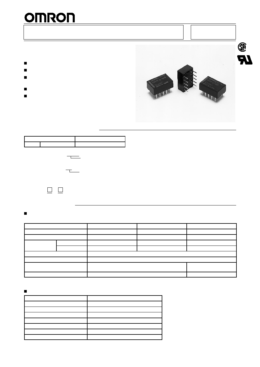
Surface Mount Relay
G6H≠2F
Low Profile, Miniature, Surface Mount
Relay
Ultra low profile only 5.2mm.
Can be soldered by VPS or IRS methods.
Impulse withstand voltage meets FCC and CCITT
rules.
Low power consumption, 140mW.
Available on tape for automatic insertion.
Ordering Information
Classification
Single-side stable
DPDT
Fully sealed
G6H-2F
Note:
1. When ordering, add the rated coil voltage to the model number.
Example: G6H-2F 12 VDC
2. When ordering tape packing, add `TR' to the model number.
Example: G6H-2F TR 12 VDC
3. `TR'is not part of the relay model number, it is not marked on the relay case.
Rated coil voltage
Tape packing
Model Number Legend:
1.
Taped Version
TR:
Taped right
TL:
Taped left
2.
Rated Coil Voltage
5, 12, 24 VDC
G6H≠2F -
1
2
Specifications
Coil Ratings
Single-side Stable Types
Rated voltage
5 VDC
12 VDC
24 VDC
Rated current
28.1 mA
11.7 mA
8.3 mA
Coil resistance
178
1,028
2,880
Coil inductance
Armature OFF
0.065
0.43
1.2
(H) (ref. value)
Armature ON
0.058
0.37
1.0
Must operate voltage
75% max. of rated voltage
Must release voltage
10% min. of rated voltage
Max. voltage
200% of rated voltage at 23
_
C, 150% at 70
_
C
170% of rated voltage at
23
_
C, 130% at 70
_
C
Power consumption
Approx. 140 mW
Approx. 200 mW
Note:
1. The rated current and coil resistance are measured at a coil temperature of 23
_
C with a tolerance of
±
10%.
2. Operating characteristics are measured at a coil temperature of 23
_
C.
Contact Ratings
Load
Resistive load (cos
= 1)
Rated load
0.5 A at 125 VAC; 1 A at 30 VDC
Contact material
Ag (Au-clad)
Rated carry current
1 A
Max. switching voltage
125 VAC, 110 VDC
Max. switching current
1 A
Max. switching capacity
62.5 VA, 33 W
Min. permissible load
10
µ
A at 10 mVDC
Note:
P level:
60
= 0.1 x 10
-6
/operation
Characteristics
Contact resistance
60 m
max.
Operate (set) time
3 ms max. (mean value: approx. 2 ms)
Release (reset) time
2 ms max. (mean value: approx. 1 ms)
Bounce time
Operate: 0.5 ms max.
Release: 0.5 ms max.
Max. operating frequency
Mechanical: 36,000 operations/hr
Electrical:
1,800 operations/hr (under rated load)
Insulation resistance
1,000 M
min. (at 500 VDC)
Dielectric withstand voltage
1,000 VAC, 50/60 Hz for 1 min between coil and contacts
1,000 VAC, 50/60 Hz for 1 min between contacts of different polarity
750 VAC, 50/60 Hz for 1 min between contacts of same polarity
Impulse withstand voltage
1,500 V 10 x 160
µ
s between contacts of same polarity (conforms to FCC Part 68)
Vibration resistance
Destruction: 10 to 55 Hz, 5-mm double amplitude
Malfunction: 10 to 55 Hz, 3-mm double amplitude
Shock resistance
Destruction: 1,000 m/s
2
(approx. 100G)
Malfunction: 500 m/s
2
(approx. 50G)
Life expectancy
Mechanical: 100,000,000 operations min. (at 36,000 operations/hr)
Electrical:
200,000 operations min. (0.1 A at 110 VAC inductive load)
Ambient temperature
Operating: ≠40
_
C to 85
_
C (with no icing)
Ambient humidity
Operating: 35% to 85%
Weight
Approx. 1.5 g
Note:
The data shown above are initial values.
Approved by Standards
UL114, UL478 (File No. E41515)/CSA C22.2 No. 0, No. 14 (File No. LR24825)
Model
Contac tform
Contac tform
Contact form
G6H≠2F
DPDT
3 to 48 VDC
1A, 30 VDC
0.3A, 100 VDC
0.5A, 125 VDC
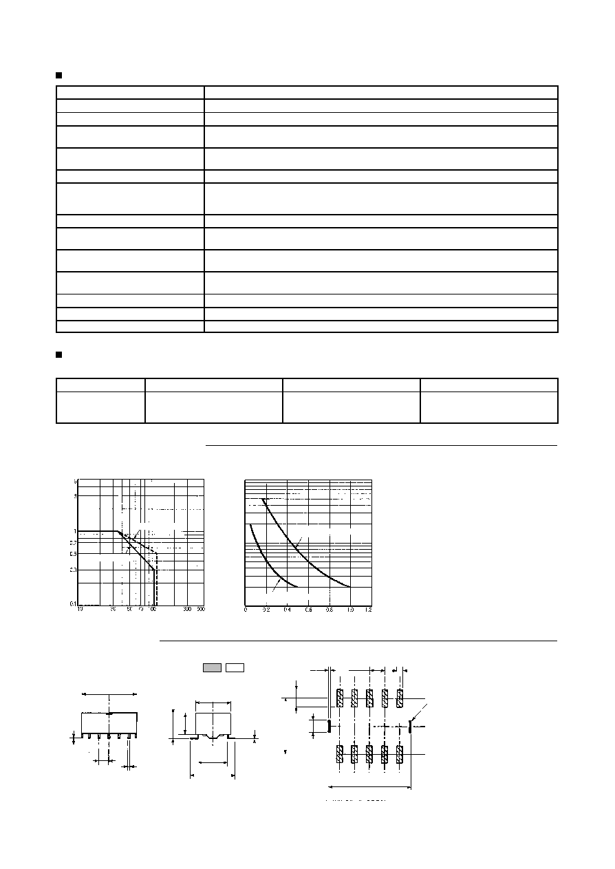
Engineering Data
Max. Switching Capacity
Life Expectancy
Switching current (A)
Switching voltage (V)
Switching current (A)
Life expectancy (x10 operations)
3
AC resistive load
DC resistive load
30-VDC resistive load
125-VAC resistive load
10,000
7,000
5,000
3,000
1,000
700
500
300
100
Dimensions
0.3
2.54
1
2.94
2
9.56
14
9
0.25
7.62
11.5
5.2
6.5
14
0.2
2.54
0.5
Note: Orientation marks are as follows:
Glue Pads
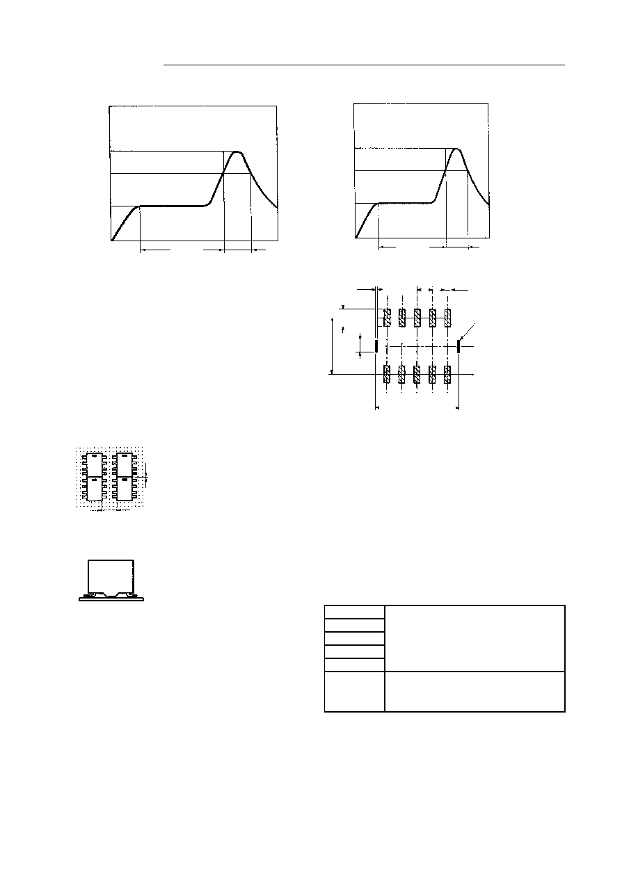
Precautions
Surface Temperature of PC Board VS. Recommended Soldering Time
1. VPS
2. IRS
Time (s)
Time (s)
215
_
C max.
Preheating
Soldering
Air
cooling
T
emperature ( C)
_
T
emperature ( C)
220
to
240
180
to
200
150
20 to 30
_
215
180
to
200
90
to
100
90 to 120
40 to 60
Preheating
Soldering
Air
cooling
90 to 120
3. Other Considerations
∑
Soldering iron heat
Temperature at tip: 280
_
C to 300
_
C
Power: 30 W to 60 W
Heating time: 3 s to 5 s
∑
When soldering with a pulse heater, hot air, or laser, take into
account such factors as heat stress, and test the process under
actual conditions.
Mounting
∑
Can be mounted in any orientation.
∑
Not suitable for socket mounting.
∑
Do not reverse the coil polarity.
∑
The diagram below the minimum spacing necessary when
mounting more than one relay on a printed circuit board.
2,54 mm min.
Surface Mounting Terminals
Terminals
L Terminals (G6H≠2F)
Characteristics
∑
Soldering methods
IRS (Infrared radiation furnace)
VPS (Vapor phase)
∑
Removal and replacement is simple.
Glue pads
Glue Pads
Glue pads are projections from the relay case where adhesive is
applied to temporarily attach the relay to the printed circuit board
before soldering. The soldering points are where solder is applied
during soldering.
∑
Glue pads are for use with epoxy or UV adhesives. Glue pads
are located on the sides to allow UV illumination and adhesive
curing. Two points are provided for stability.
Orientation Marks
These marks are provided to properly position the relays when they
are supplied to the printed circuit board automatically. Two types of
orientation marks are provided.
∑
Mechanical: A U-shaped impression along the top edge is used
for alignment.
∑
Optical: A dark mark on the top surface is used for alignment.
Cleaning Methods
Brushing
Fine as long as the detergent has no chemical
Dipping
or electrical affect on the relay.
Spraying
Vapor
Hot water
Ultrasonic
Fine as long as the detergent has no chemical
or electrical affect on the relay. The model
number of the ultrasound cleaning-type relay
ends in "-U".
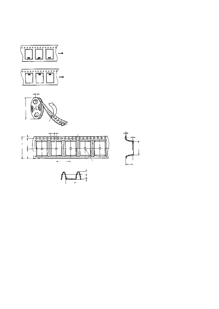
Tape Packing
∑
Taping method
Tape type: TE2416R (or L)
Reel type: R53
There are 500 relays per reel.
Relay orientation:
G6H≠2F≠TL
G6H-2F-TR
Direction
Direction
29.5
Cover tape
1.55 dia.
2
4
1.75
24
11.5
(10.75)
16
1.5 dia. min.
12.1
0.3
4
R0.3 max.
0.3
330
Carrier
tape
emboss tape
Dimensions
0.38
±
0.05
14.5
±
0.1
6.9
±
0.1