508
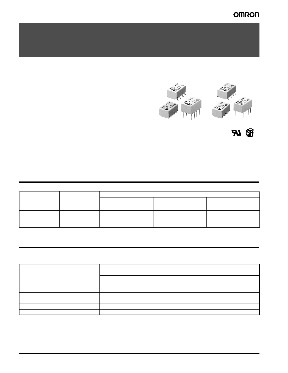
Low Signal Relay
G6K
Low Signal Relay
G6K
∑ Fourth generation design.
∑ Design based on worldwide
communications, computer peripheral
and office automation relay requirements.
∑ Offers excellent board space savings.
∑ Meets 2.5 kV Bellcore surge
requirements.
∑ Terminal design based on Omron's
successful G6S relay.
∑ Available in PCB through-hole, SMT gullwing and SMT
"inside-L" terminals.
∑ Ambient temperature range of -40 to +85∞C.
∑ Complies with UL1950 Basic Insulation
at 125 V.
∑ Available in 2.54 and 3.2 mm coil-contact terminal spacing
versions.
∑ Available in single coil latching.
∑ RoHS Compliant.
Ordering Information
To Order: Select the part number and add the desired coil voltage rating (e.g., G6K-2F-
DC5
).
Specifications
I
Contact data
Terminal
Contact form
Model
Non-latching
2.54 mm spacing
Non-latching
3.2 mm coil-contact
terminal spacing
Single coil latching
3.2 mm coil-contact
terminal spacing
Gullwing
DPDT
G6K-2F
G6K-2F-Y
G6KU-2F-Y
Inside "L"
DPDT
G6K-2G
G6K-2G-Y
G6KU-2G-Y
PCB through-hole
DPDT
G6K-2P
G6K-2P-Y
G6KU-2P-Y
Load
Resistive load (cos
=1)
Rated load
0.3 A at 125 VAC
1 A at 30 VDC
Contact material
Ag (Au clad)
Max. carry current
1 A
Max. operating voltage
125 VAC, 60 VDC
Max. operating current
1 A
Max. switching capacity
37.5 VA, 30W
Min. permissible load
10
µA at 10 mVDC
Low Signal Relay
G6K
509
G6K- 2.5 mm coil-contact terminal spacing, standard, non-latching (G6K-2F, G6K-2G, G6K-2P)
G6K- 3.2 mm coil-contact terminal spacing, non-latching (G6K-2F-Y, G6K-2G-Y, G6K-2P-Y
)
G6KU- 3.2 mm spacing, single coil latching (G6KU-2F-Y, G6KU-2G-Y, G6KU-2P-Y)
Note: 1.
The rated current and coil resistance are measured at a coil temperature of 23∞C (73∞F) with a tolerance of ± 10%.
2.
The operating characteristics are measured at a coil temperature of 23∞C (73∞F) unless otherwise specified.
3.
Pick-up voltage is measured with no carry current across the contacts.
4.
Pick-up voltage will vary with temperature.
5.
Specifications subject to change without notice.
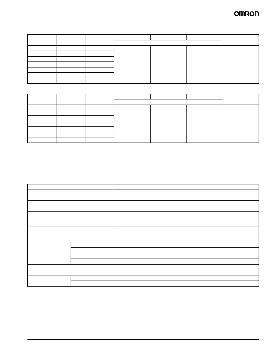
I
Characteristics
Note:
Data shown are of initial value.
Rated voltage
(VDC)
Rated current
(mA)
Coil resistance
(
)
Pick-up voltage
Dropout voltage
Maximum voltage
Power consumption
(mW)
% of rated value
3
33.0
91
80% max.
10% min.
150% max.
(at 85∞C)
100 (approx.)
4.5
23.2
194
5
21.1
237
6
17.6
341
9
11.3
795
12
9.1
1,315
24
4.6
5,220
Rated voltage
(VDC)
Rated current
(mA)
Coil resistance
(
)
Set-up voltage
Reset voltage
Maximum voltage
Power consumption
(mW)
% of rated value
3
33.0
91
80% max.
80 % min.
150% max.
(at 85∞C)
100 (approx.)
4.5
23.2
194
5
21.1
237
6
17.6
341
9
11.3
795
12
9.1
1,315
24
4.6
5,220
Contact resistance (initial)
100 m
max.
Operate time (set time)
3 ms max.
Release time (reset time)
3 ms max.
Bounce time
3 ms max
Insulation resistance
1,000 M
min. (at 500 VDC)
Dielectric strength
1,500 VAC for 1 minute between coil contacts
1,000 VAC for 1 minute between contacts of different poles
750 VAC for 1 minute between contacts of the same pole
Surge withstand voltage
2,500 V, 2x10
µs (conforms to Bellcore specifications) between coil and contacts
1,500 V, 10x160
µs (conforms to FCC Part 68) between contacts of different poles
1,500 V, 10x160
µs (conforms to FCC Part 68) between contacts of the same pole
Vibration
Mechanical durability
10 to 55 Hz; 5.0 mm double amplitude
Malfunction durability
10 to 55 Hz; 3.3 mm double amplitude
Shock
Mechanical durability
1,000 m/s
2
, approx. 100G
Malfunction durability
750 m/s
2
, approx. 75G
Ambient temperature
-40
∞C to 85∞C (-40∞F to 185∞F)
Humidity
35 to 85% RH
Service life
Mechanical
50,000,000 operations min. (at 36,000 operations per hour)
Electrical
100,000 operations min. at rated load (at 1,800 operations per hour)

510
Low Signal Relay
G6K
I
Characteristic data
Max. Switching Capacity
Ambient Temperature vs.
Ambient Temperature vs.
Maximum Coil Voltage
Pick-up and Dropout Voltage
Electrical Service Life
High-frequency Characteristics
Isolation
Insertion Loss
VSWR and Return Loss
Switching voltage (V)
Ambient temperature (
∞
C)
Ambient temperature (
∞
C)
Switch
in
g
cu
r
r
e
n
t (
A
)
Max
i
m
u
m v
o
l
t
age
(%
)
On t
he
basi
s
of ra
ted
v
o
l
t
ag
e (
%
)
Switching current (A)
Service life (x10
3
operations)
resistive load: 1A, 30VDC
Service life (x10
3
operations)
resistive load: 10
µ
A, 10mVDC
S
w
i
t
c
h
i
n
g
op
er
at
i
o
n (
x
10
4
op
e
r
at
i
o
ns
)
C
o
nt
a
c
t
r
e
si
st
a
n
c
e
(
m
)
Co
nta
c
t r
e
sista
n
ce
(
m
)
Frequency (MHz)
Frequency (MHz)
Frequency (MHz)
I
s
ol
at
i
o
n (
d
B
)
Inse
r
t
ion lo
ss (
d
B
)
Re
tu
r
n
lo
ss (
d
B)
Low Signal Relay
G6K
511
I
Approvals
UL (File No. E41515) / CSA (File No. LR24825)
Note:
Complies with UL1950 Basic Insulation at 125 V (pollution degree 1 for internal spacings, pollution degree 2 for external spacings).
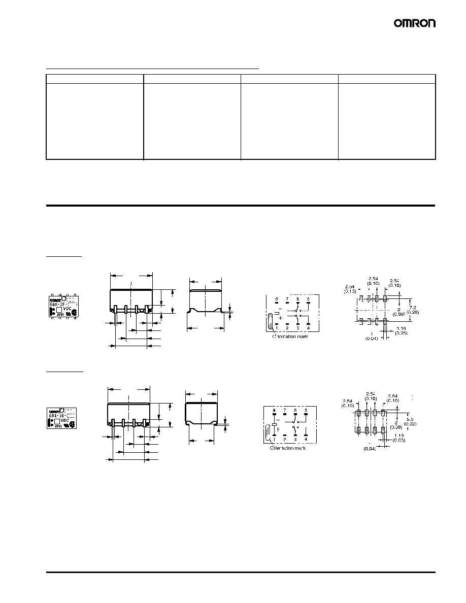
Dimensions
Unit: mm (inch)
I
Relays
G6K-2F
G6K-2G
Type
Contact form
Coil rating
Contact ratings
G6K-2F
G6K-2G
G6K-2P1
G6K-2F-Y
G6K-2G-Y
G6K-2P-Y
G6KU-2F-Y
G6KU-2G-Y
G6KU-2P-Y
DPDT
3 to 24 VDC
0.3 A, 125 VAC
0.5 A, 60 VDC
1 A, 30 VDC
7.62 (0.30)
5.08 (0.20)
2.54 (0.10)
1.19 (0.04)
5.2 ±0.2
(0.20)
1.6 (0.06)
10 ±0.2
(0.39)
0.5
(0.02)
6.5 ±0.2
(0.26)
0.3
(0.012)
7.8
(0.31)
Terminal arrangement/
Internal connections
(top view)
Mounting pads
(top view)
7.62 (0.30)
5.08 (0.20)
2.54 (0.10)
1.19 (0.04)
5.2 ±0.2
(0.20)
1.6 (0.06)
10 ±0.2
(0.39)
0.5
(0.02)
6.5 ±0.2
(0.26)
0.3
(0.012)
4.9
(0.19)
Terminal arrangement/
Internal connections
(top view)
Mounting pads
(top view)

512
Low Signal Relay
G6K
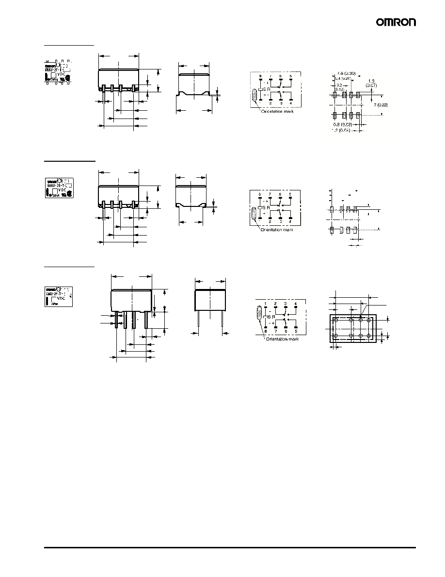
G6K-2P
G6K-2F-Y
G6K-2G-Y
G6K-2P-Y
2.54 (0.10)
2.54 (0.10)
2.54 (0.10)
3.5 (0.14)
0.1
(0.003)
5 ±0.3
(0.20)
10 ±0.2
(0.39)
R0.2
0.4 (0.016)
0.5 (0.02)
6.5 +0.2
(0.26)
5.08
(0.20)
Terminal arrangement/
Internal connections
(bottom view)
Mounting pads
(bottom view)
7.6 (0.30)
5.4 (0.21)
3.2 (0.12)
1.2 (0.04)
0.5
(0.02)
5.2 ±0.2
(0.20)
1.6 (0.06)
10 ±0.2
(0.39)
6.5 ±0.2
(0.26)
0.3
(0.012)
7.8
(0.31)
Terminal arrangement/
Internal connections
(top view)
Mounting pads
(top view)
7.6 (0.30)
5.4 (0.21)
3.2 (0.12)
1.2 (0.04)
0.5
(0.02)
5.2 ±0.2
(0.20)
1.6 (0.06)
10 ±0.2
(0.39)
6.5 ±0.2
(0.26)
0.3
(0.012)
4.9
(0.19)
7.6 (0.30)
5.7 (0.22)
0.8 (0.03)
1.2 (0.04)
5.4 (0.21)
3.2
(0.12)
1.8
(0.07)
Terminal arrangement/
Internal connections
(top view)
Mounting pads
(top view)
3.2 (0.12)
5.4 (0.21)
7.6 (0.30)
1.2 (0.04)
3.5
(0.14)
5
(0.20)
10 ±0.2
(0.39)
0.4 (0.016)
0.5 (0.02)
0.1
(0.003)
6.5 +0.2
(0.26)
5.08 ±0.15
(0.20)
7.6 (0.30)
5.4 (0.21)
1.2 (0.05)
Eight,
0.85-dia.
holes
0.71
(0.03)
5.08 ±0.1
(0.20)
3.2
(0.12)
Terminal arrangement/
Internal connections
(bottom view)
Mounting pads
(bottom view)
Low Signal Relay
G6K
513
G6KU-2F-Y
G6KU-2G-Y
G6KU-2P-Y
7.6 (0.30)
5.4 (0.21)
3.2 (0.12)
1.2 (0.04)
0.5
(0.02)
5.2 ±0.2
(0.20)
1.6 (0.06)
10 ±0.2
(0.39)
6.5 ±0.2
(0.26)
0.3
(0.012)
7.8
(0.31)
Terminal arrangement/
Internal connections
(top view)
Mounting pads
(top view)
7.6 (0.30)
5.4 (0.21)
3.2 (0.12)
1.2 (0.04)
0.5
(0.02)
5.2 ±0.2
(0.20)
1.6 (0.06)
10 ±0.2
(0.39)
6.5 ±0.2
(0.26)
0.3
(0.012)
4.9
(0.19)
7.6 (0.30)
5.7 (0.22)
0.8 (0.03)
1.2 (0.04)
5.4 (0.21)
3.2
(0.12)
1.8
(0.07)
Terminal arrangement/
Internal connections
(top view)
Mounting pads
(top view)
3.2 (0.12)
5.4 (0.21)
7.6 (0.30)
1.2 (0.04)
3.5
(0.14)
5
(0.20)
10 ±0.2
(0.39)
0.4 (0.016)
0.5 (0.02)
0.1
(0.003)
6.5 +0.2
(0.26)
5.08 ±0.15
(0.20)
7.6 (0.30)
5.4 (0.21)
1.2 (0.05)
Eight,
0.85-dia.
holes
0.71
(0.03)
5.08 ±0.1
(0.20)
3.2
(0.12)
Terminal arrangement/
Internal connections
(bottom view)
Mounting pads
(bottom view)
514
Low Signal Relay
G6K
I
Accessories
Relays in tube packing are arranged so that the orientation mark of each Relay is on the left side. Be sure to reference Relay orientation when
mounting the Relay to the PCB.
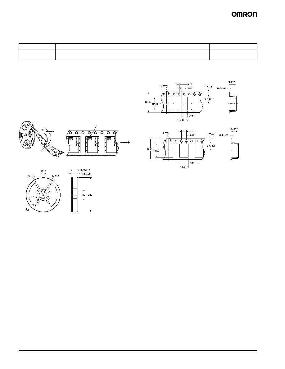
I
Tape and Reel Dimensions
∑
Tape type: ETX7200 (EIAJ - Electronic Industrial Association of
Japan)
∑
16 mm tape meets EIA Standards
5.6 mm pocket depth
12 mm pitch
4 mm sprocket pitch
∑
Reel type: RPM-16D (EIAJ), 330 mm
∑
Relays per reel: 900
1. Direction of Relay Insertion
2. Reel Dimensions
3. Carrier Tape Dimensions
Tube packing
Standard nomenclature
50 pcs per anti-static tube
Tape packing
When ordering, add "TR" before the rated coil voltage (e.g., G6K-2G-TR-DC5).
Note: TR is not part of the relay model number and will not be marked on the relay.
900 pcs per reel
(see details below)
Carrier tape
Top tape
(cover tape)
Emboss tape
Orientation mark
Pulling
direction

Low Signal Relay
G6K
515
Precautions
I
Correct Use
Handling
Do not unpack the relay until mounting it.
Soldering
Solder: JIS Z3282, H63A or equivalent
Soldering temperature: Approx. 250∞C (260∞C if the DWS method is
used)
Soldering time: Approx. 5 s max. (approx. 2 s for the first time and
approx. 3 s for the second time if the DWS method is used)
Be sure to make a molten solder level adjustment so that the solder
will not overflow on the PCB.
Claw Securing Force During Automatic
Mounting
During automatic insertion of Relays, make sure to set the securing
force of each claw to the following so that the Relays characteristics
will be maintained.
Environmental Conditions During
Operation, Storage, and Transportation
It is best to keep the relay in its packaging in a controlled environ-
ment until it is ready for mounting.
If the Relay is stored for a long time in an adverse environment with
high temperature, high humidity, organic gases, or sulfide gases, sul-
fide or oxide films will form on the contact surfaces. These films may
result in unstable contact, contact problems, or functional problems.
Therefore, operate, store, or transport the product under specified
environmental conditions.
Latching Relay Mounting
Make sure that the vibration or shock that is generated from other
devices, such as relays in operation, on the same panel and imposed
on the Latching Relay does not exceed the rated value, otherwise the
Latching Relay that has been set may be reset or vice versa. The
Latching Relay is reset before shipping. If excessive vibration or
shock is imposed, however, the Latching Relay may be set acciden-
tally. Be sure to apply a reset signal before use.
Maximum Allowable Voltage
The maximum allowable voltage of the coil can be obtained from the
coil temperature increase and the heat-resisting temperature of coil
insulating sheath material. (Exceeding the heat-resisting tempera-
ture may result in burning or short-circuiting.) The maximum allow-
able voltage also involves important restrictions which include the
following:
∑
Must not cause thermal changes in or deterioration of the insulating
material.
∑
Must not cause damage to other control devices.
∑
Must not cause any harmful effect on people.
∑
Must not cause fire.
Therefore, be sure to use the maximum allowable voltage as speci-
fied in the catalog.
As a rule, the rated voltage must be applied to the coil. A voltage
exceeding the rated value, however, can be applied to the coil pro-
vided that the voltage is less than or equal to the maximum allowable
voltage. It must be noted that continuous voltage application to the
coil will cause a coil temperature increase which may affect charac-
teristics such as electrical life and coil insulation.
Coating
The Relay mounting on the PCB may be coated or washed but do not
apply silicone coating or detergent containing silicone, otherwise the
silicone coating or detergent may remain on the surface of the Relay.
PCB Mounting
If two or more Relays are closely mounted with the long sides of the
Relays facing each other and soldering is performed with infrared
radiation, the solder may not be properly exposed to the infrared
rays. Be sure to keep the proper distance between adjacent Relays
as shown below to insure formation of good solder joints.
Two or more Relays may be mounted as closely as desired with the
short sides of the Relays facing each other.
Direction A: 1.96 N
Direction B: 4.90 N
Direction C: 1.96 N
G6K-2G
G6K-2F

Terms and Conditions of Sale
1.
Offer; Acceptance. These terms and conditions (these "Terms") are deemed
part of all quotations, acknowledgments, invoices, purchase orders and other
documents, whether electronic or in writing, relating to the sale of products or
services (collectively, the "Products") by Omron Electronic Components LLC
("Seller"). Seller hereby objects to any terms or conditions proposed in
Buyer's purchase order or other documents which are inconsistent with, or in
addition to, these Terms.
2. Prices;
Payment. All prices stated are current, subject to change without
notice by Seller. Buyer agrees to pay the price in effect at time of shipment.
Payments for Products received are due net 30 days unless otherwise stated
in the invoice.
3. Discounts. Cash discounts, if any, will apply only on the net amount of
invoices sent to Buyer after deducting transportation charges, taxes and
duties, and will be allowed only if (i) the invoice is paid according to Seller's
payment terms and (ii) Buyer has no past due amounts owing to Seller.
4. Currencies. If the prices quoted herein are in a currency other than U.S. dol-
lars, Buyer shall make remittance to Seller at the then current exchange rate
most favorable to Seller and which is available on the due date; provided that if
remittance is not made when due, Buyer will convert the amount to U.S. dol-
lars at the then current exchange rate most favorable to Seller available during
the period between the due date and the date remittance is actually made.
5. Governmental
Approvals. Buyer shall be responsible for, and shall bear all
costs involved in, obtaining any government approvals required for the impor-
tation or sale of the Products.
6. Taxes. All taxes, duties and other governmental charges (other than general
real property and income taxes), including any interest or penalties thereon,
imposed directly or indirectly on Seller or required to be collected directly or
indirectly by Seller for the manufacture, production, sale, delivery, importation,
consumption or use of the Products sold hereunder (including customs duties
and sales, excise, use, turnover and license taxes) shall be charged to and
remitted by Buyer to Seller.
7. Financial. If the financial position of Buyer at any time becomes unsatisfactory
to Seller, Seller reserves the right to stop shipments or require satisfactory
security or payment in advance. If Buyer fails to make payment or otherwise
comply with these Terms or any related agreement, Seller may (without liability
and in addition to other remedies) cancel any unshipped portion of Products
sold hereunder and stop any Products in transit until Buyer pays all amounts,
including amounts payable hereunder, whether or not then due, which are
owing to it by Buyer. Buyer shall in any event remain liable for all unpaid
accounts.
8. Cancellation; Etc. Orders are not subject to rescheduling or cancellation
unless Buyer indemnifies Seller fully against all costs or expenses arising in
connection therewith.
9. Force
Majeure. Seller shall not be liable for any delay or failure in delivery
resulting from causes beyond its control, including earthquakes, fires, floods,
strikes or other labor disputes, shortage of labor or materials, accidents to
machinery, acts of sabotage, riots, delay in or lack of transportation or the
requirements of any government authority.
10. Shipping; Delivery. Unless otherwise expressly agreed in writing by Seller:
1. Shipments shall be by a carrier selected by Seller;
2. Such carrier shall act as the agent of Buyer and delivery to such carrier
shall constitute delivery to Buyer;
3. All sales and shipments of Products shall be FOB shipping point (unless
otherwise stated in writing by Seller), at which point title to and all risk of
loss of the Products shall pass from Seller to Buyer, provided that Seller
shall retain a security interest in the Products until the full purchase price is
paid by Buyer;
4. Delivery and shipping dates are estimates only.
5. Seller will package Products as it deems proper for protection against
normal handling and extra charges apply to special conditions.
11. Claims. Any claim by Buyer against Seller for shortage or damage to the
Products occurring before delivery to the carrier must be presented in writing
to Seller within 30 days of receipt of shipment and include the original trans-
portation bill signed by the carrier noting that the carrier received the Products
from Seller in the condition claimed.
12. Warranties. (a) Exclusive Warranty. Seller's exclusive warranty is that the
Products will be free from defects in materials and workmanship for a period of
twelve months from the date of sale by Seller (or such other period expressed
in writing by Seller). Seller disclaims all other warranties, express or implied.
(b) Limitations. SELLER MAKES NO WARRANTY OR REPRESENTATION,
EXPRESS OR IMPLIED, ABOUT NON-INFRINGEMENT, MERCHANTABIL-
ITY OR FITNESS FOR A PARTICULAR PURPOSE OF THE PRODUCTS.
BUYER ACKNOWLEDGES THAT IT ALONE HAS DETERMINED THAT THE
PRODUCTS WILL SUITABLY MEET THE REQUIREMENTS OF THEIR
INTENDED USE. Seller further disclaims all warranties and responsibility of
any type for claims or expenses based on infringement by the Products or oth-
erwise of any intellectual property right. (c) Buyer Remedy. Seller's sole obli-
gation hereunder shall be to replace (in the form originally shipped with Buyer
responsible for labor charges for removal or replacement thereof) the non-
complying Product or, at Seller's election, to repay or credit Buyer an amount
equal to the purchase price of the Product; provided that in no event shall
Seller be responsible for warranty, repair, indemnity or any other claims or
expenses regarding the Products unless Seller's analysis confirms that the
Products were properly handled, stored, installed and maintained and not sub-
ject to contamination, abuse, misuse or inappropriate modification. Return of
any Products by Buyer must be approved in writing by Seller before shipment.
Seller shall not be liable for the suitability or unsuitability or the results from the
use of Products in combination with any electrical or electronic components,
circuits, system assemblies, or any other materials or substances or environ-
ments. Any advice, recommendations or information given orally or in writing
are not to be construed as an amendment or addition to the above warranty.
13. Limitation on Liability; Etc. SELLER SHALL NOT BE LIABLE FOR SPECIAL,
INDIRECT, INCIDENTAL OR CONSEQUENTIAL DAMAGES, LOSS OF
PROFITS OR PRODUCTION OR COMMERCIAL LOSS IN ANY WAY CON-
NECTED WITH THE PRODUCTS, WHETHER SUCH CLAIM IS BASED IN
CONTRACT, WARRANTY, NEGLIGENCE OR STRICT LIABILITY. Further, in
no event shall liability of Seller exceed the individual price of the Product on
which liability is asserted.
14. Indemnities. Buyer shall indemnify and hold harmless Seller, its affiliates and
its employees from and against all liabilities, losses, claims, costs and
expenses (including attorney's fees and expenses) related to any claim, inves-
tigation, litigation or proceeding (whether or not Seller is a party) which arises
or is alleged to arise from Buyer's acts or omissions under these Terms or in
any way with respect to the Products. Without limiting the foregoing, Buyer (at
its own expense) shall indemnify and hold harmless Seller and defend or settle
any action brought against Seller to the extent that it is based on a claim that
any Product made to Buyer specifications infringed intellectual property rights
of another party.
15. Property; Confidentiality. The intellectual property embodied in the Products is
the exclusive property of Seller and its affiliates and Buyer shall not attempt to
duplicate it in any way without the written permission of Seller. Notwithstand-
ing any charges to Buyer for engineering or tooling, all engineering and tooling
shall remain the exclusive property of Seller. All information and materials sup-
plied by Seller to Buyer relating to the Products are confidential and propri-
etary, and Buyer shall limit distribution thereof to its trusted employees and
strictly prevent disclosure to any third party.
16. Miscellaneous. (a) Waiver. No failure or delay by Seller in exercising any right
and no course of dealing between Buyer and Seller shall operate as a waiver
of rights by Seller. (b) Assignment. Buyer may not assign its rights hereunder
without Seller's written consent. (c) Law. These Terms are governed by Illi-
nois law (without regard to conflict of law principles). Federal and state courts
in Illinois shall have exclusive jurisdiction for any dispute hereunder.
(d) Amendment. These Terms constitute the entire agreement between Buyer
and Seller relating to the Products, and no provision may be changed or
waived unless in writing signed by the parties. (e) Severability. If any provision
hereof is rendered ineffective or invalid, such provision shall not invalidate any
other provision. (f) Setoff. Buyer shall have no right to set off any amounts
against the amount owing in respect of this invoice.. (g) Definitions. As used
herein, "including" means "including without limitation".

Certain Precautions on Specifications and Use
1. Suitability for Use. Seller shall not be responsible for conformity with any stan-
dards, codes or regulations which apply to the combination of the Product in
Buyer's application or use of the Product. At Buyer's request, Seller will pro-
vide applicable third party certification documents identifying ratings and limita-
tions of use which apply to the Product. This information by itself is not
sufficient for a complete determination of the suitability of the Product in combi-
nation with the end product, machine, system, or other application or use.
Buyer shall be solely responsible for determining appropriateness of the partic-
ular Product with respect to Buyer's application, product or system. Buyer
shall take application responsibility in all cases but the following is a non-
exhaustive list of applications for which particular attention must be given:
(i) Outdoor use, uses involving potential chemical contamination or electrical
interference, or conditions or uses not described in this document.
(ii) Energy control systems, combustion systems, railroad systems, aviation
systems, medical equipment, amusement machines, vehicles, safety
equipment, and installations subject to
separate industry or government regulations.
(iii)Use in consumer products or any use in significant quantities.
(iv)Systems, machines and equipment that could present a risk to life or
property. Please know and observe all prohibitions of use applicable to this
product.
NEVER USE THE PRODUCT FOR AN APPLICATION INVOLVING SERIOUS
RISK TO LIFE OR PROPERTY WITHOUT ENSURING THAT THE SYSTEM
AS A WHOLE HAS BEEN DESIGNED TO ADDRESS THE RISKS, AND THAT
THE OMRON PRODUCT IS PROPERLY RATED AND INSTALLED FOR THE
INTENDED USE WITHIN THE OVERALL EQUIPMENT OR SYSTEM.
2. Programmable Products. Seller shall not be responsible for the user's
programming of a programmable product, or any consequence thereof.
3. Performance Data. Performance data given in this publication is provided as a
guide for the user in determining suitability and does not constitute a warranty.
It may represent the result of Seller's test conditions, and the users must corre-
late it to actual application requirements. Actual performance is subject to
Seller's Warranty and Limitations of Liability.
4. Change in Specifications. Product specifications and accessories may be
changed at any time based on improvements and other reasons. It is our prac-
tice to change part numbers when published ratings or features are changed,
or when significant construction changes are made. However, some specifica-
tions of the Product may be changed without any notice. When in doubt, spe-
cial part numbers may be assigned to fix or establish key specifications for your
application. Please consult with your Seller representative at any time to con-
firm actual specifications of purchased Product.
5. Errors and Omissions. The information in this publication has been carefully
checked and is believed to be accurate; however, no responsibility is assumed
for clerical, typographical or proofreading errors, or omissions.
6. RoHS Compliance. Where indicated, our products currently comply, to the best
of our knowledge as of the date of this publication, with the requirements of the
European Union's Directive on the Restriction of certain Hazardous Sub-
stances ("RoHS"), although the requirements of RoHS do not take effect until
July 2006. These requirements may be subject to change. Please consult our
website for current information.
OMRON ON-LINE
Global - http://www.omron.com
USA - http://www.components.omron.com
Canada - http://www.omron.ca
Cat. No. JB301-E3-01
Printed in USA
OMRON CANADA, INC.
885 Milner Avenue
Toronto, Ontario M1B 5V8
416-286-6465
OMRON ELECTRONIC
COMPONENTS LLC
55 E. Commerce Drive, Suite B
Schaumburg, IL 60173
847-882-2288
3/05 Specifications subject to change without notice
Complete "Terms and Conditions of Sale" for product purchase and use are on Omron's website
at www.components.omron.com ≠ under the "About Us" tab, in the Legal Matters section.
ALL DIMENSIONS SHOWN ARE IN MILLIMETERS.
To convert millimeters into inches, multiply by 0.03937. To convert grams into ounces, multiply by 0.03527.