552
High-frequency Relay
G6W
High-frequency Relay
G6W
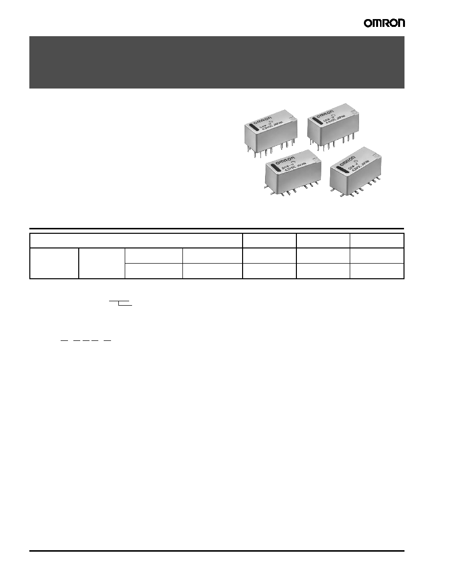
Surface-mountable 5 GHz Band Miniature
SPDT High-frequency Relay
∑ Superior high-frequency characteristics, such as an isolation
of 60 dB min., insertion loss of 0.2 dB max., and V.S.W.R of
1.2 max. at 5 GHz (50
).
∑ High-frequency characteristics obtained by adopting
tri-plate micro strip line design.
∑ Small size at 20 x 9.4 x 8.9 mm (L x W x H).
∑ Y-shape terminal arrangement simplifies wiring to PCBs.
∑ SMT and latching versions available.
∑ RoHS Compliant.
Ordering Information
I Typical Applications
∑ Mobile phone base station (W-CDMA, UMTS, CDMA-2000, PCS)
∑ Wireless LAN
∑ Measurement devices
Classification
Non latching
Single-coil
latching
Dual-coil
latching
SPDT
Fully sealed
Through-hole
terminal
Y-shape terminal
G6W-1P
G6WU-1P
G6WK-1P
Surface-mount
terminal
Y-shape terminal
G6W-1F
G6WU-1F
G6WK-1F
Note:
When ordering, add the rated coil voltage to the model number.
Example: G6W-1P 12 VDC
Model Number Legend:
Rated coil voltage
G 6 W
-
-
1 2 3 4 5
1.
Relay function
None: Non-latching
U:
Single-coil latching
K:
Dual-coil latching
2.
Contact form
1:
SPDT
3.
Terminal shape
F:
Surface-mount terminals
P:
PCB through-hole terminals
4.
Terminal Structure
None: Y-shape terminal
(standard)
5.
Contact Arrangement
None: Standard contact arrangement
R:
Reverse contact arrangement
High-frequency Relay
G6W
553
Specifications
I Contact Ratings
I High-frequency Characteristics
Note: 1. The above values are initial values.
2. These values are for a load with V.SWR
1.2 at an impedance of 50 .
I Coil Ratings
Non-latching Relays (G6W-1F, G6W-1P)
Single-coil Latching Relays (G6WU-1F, G6WU-1P)
Dual-coil Latching Relays (G6WK-1F, G6WK-1P)
Note: 1. The rated current and coil resistance are measured at a coil temperature of 23
∞C with a tolerance of ± 10%.
2. The operating characteristics are measured at a coil temperature of 23
∞C.
3. The maximum voltage is the highest voltage that can be imposed on the relay coil.
Item Load
Resistive load
Rated load
10 mA at 30 VAC
10 mA at 30 VDC
2.5 GHz, 50
, 10 W (See note)
Rated carry current
0.5 A
Max. switching voltage
30 VDC, 30 VAC
Max. switching current
0.5 A
Item Frequency
2.0 GHz
2.5 GHz
5.0 GHz
Isolation
65 dB min.
60 dB min.
40 dB min.
Insertion loss
0.2 dB max.
0.4 dB min
V.SWR
1.2 max.
15 dB min.
Max. carry power
20 W (See note)
Max. switching power
10 W (See note)
Rated voltage
3 VDC
4.5 VDC
9 VDC
12 VDC
24 VDC
Rated current
66.7 mA
44.4 mA
22.2 mA
16.7 mA
8.3 mA
Coil resistance
45
101
405
720
2,880
Must operate voltage
80% of max. of rated voltage
Must release voltage
10% min. of rated voltage
Maximum voltage
150% of rated voltage
Power consumption
Approx. 200 mW
Rated voltage
9 VDC
12 VDC
Rated current
22.2 mA
16.7 mA
Coil resistance
405
720
Must set voltage
80% max. of rated voltage
Must reset voltage
80% max of rated voltage
Maximum voltage
150% of rated voltage
Power consumption
Approx. 200 mW
Rated voltage
3 VDC
4.5 VDC
9 VDC
12 VDC
24 VDC
Rated current
120 mA
80 mA
40 mA
30 mA
15 mA
Coil resistance
25
56
225
400
1,600
Must set voltage
80% max. of rated voltage
Must reset voltage
80% max. of rated voltage
Maximum voltage
150% of rated voltage
Power consumption
Approx. 360 mW

554
High-frequency Relay
G6W
I Characteristics
Note: 1. The contact resistance was measured with 10 mA at 1 VDC with a fall-of-potential method.
2. Values in parentheses are actual values.
3. The insulation resistance was measured with a 500-VDC Megger Tester applied to the same parts as those used for checking the
dielectric strength.
4. The above values are initial values.
Engineering Data
Item Classification
Non-latching
Single-coil
latching
Dual-coil
latching
Model
G6W-1F, G6W-1P
G6WU-1F, G6WU-1P
G6WK-1F, G6WK-1P
Contact resistance (See note 1)
100 m
max.
Operate (set) time (See note 2)
10 ms max. (Approx. 3.5 ms) 10 ms max. (Approx. 2.5 ms)
Release (reset) time (See note 2)
10 ms max. (Approx. 2.5 ms)
Minimum set/reset signal width
-----
12 ms
Insulation resistance (See note 3)
1,000 M
min. (at 500 VDC)
Dielectric strength
Coil and contacts
1,000 VAC, 50/60 Hz for 1 min
Coil and ground,
contacts and ground
500 VAC, 50/60 Hz for 1 min
Contact of same
polarity
500 VAC, 50/60 Hz for 1 min
Vibration resistance
Destruction
10 to 55 Hz, 1.5-mm double amplitude
Malfunction
10 to 55 Hz, 2-mm double amplitude
Shock resistance
Destruction
1,000 m/s
2
Malfunction
500 m/s
2
Endurance
Mechanical
1,000,000 operations min. (at 36,000 operations/hour)
Electrical
300,000 operations min. (with a rated load at 1,800 operations/hour)
Ambient temperature
Operating: -40
∞C to 70∞C (with no icing or condensation)
Ambient humidity
Operating: 5% to 85%
Weight
Approx. 3 g
40
20
250
200
150
100
50
0
0
20
40
60
80
100
Maximum voltage (%)
Ambient temperature (∞C)
Max. estimated value
60
40
100
90
80
70
60
50
40
30
20
10
0
0
20
20
40
60
80 100
max.
avg.
max.
min.
min.
min.
avg.
Ambient temperature (∞C)
On the basis of rated voltage (%)
Must set voltage
Must reset voltage
Z
Z'
Y
Y'
X
X'
200
400
600
800
1,000
1,000
1,000
1,000
1,000
800
600
400
200
1,000
Shock direction
X
X'
Energized
Z
Z'
Y
Y'
Unit: m/s
2
Sample: G6WK-1P 4.5VDC
Number of Relays: 10
Not
energized
Ambient Temperature vs.
Maximum Voltage
Ambient Temperature vs.
Must Set or Must Reset Voltage
Shock Malfunction
Note: "Maximum voltage" is the maximum
voltage that can be applied to the relay
coil.
Conditions: Shock is applied in
±X, ±Y, and
±Z directions three times each with and
without energizing the relays to check the
number of contact malfunctions.

High-frequency Relay
G6W
555
100
80
60
40
20
0
0.001 0.01
0.1
1
10
100
1,000
max.
max.
min.
min.
Sample: G6WU-1P 4.5 VDC
Number of Relays: 5
Test conditions: 10-mA resistive load at
30-VAC with an operation rate of 50%.
Switching frequency: 1,800 operations/h
Operating frequency (x10
3
operations)
On the basis of rated voltage (%)
Must set voltage
Must reset voltage
Electrical Endurance
(With Must Set and Must Reset
Voltage)
Electrical Endurance
(With Must Set and Must Reset
Voltage)
Sample: G6WU-1P 4.5 VDC
Number of Relays: 5
Test conditions:
10-mA resistive load at 30-VDC
Switching frequency: 1,800 operations/h
0.001 0.01
0.1
1
10
100
1,000
Contact resistance
max.
max.
min.
min.
1,000
500
300
100
50
30
10
NO contact
NC contact
Operating frequency (x10
3
operations)
Contact resistance (m
)
0.001 0.01
0.1
1
10
100
1,000
max.
max.
min.
min.
1,000
500
300
100
50
30
10
Sample: G6WU-1P 4.5 VDC
Number of Relays: 5
Test conditions:
10-mA resistive load at 30-VAC
Switching frequency: 1,800 operations/h
NO contact
NC contact
Operating frequency (x10
3
operations)
Contact resistance (m
)
Contact resistance
Electrical Endurance
(Contact Resistance)
Electrical Endurance
(Contact Resistance)
1,200
800
400
0
400
800 1,200
+30
+20
+10
0
10
20
30
Sample: G6WK-1P 4.5 VDC
Number of Relays: 5
Must set voltage
Must reset voltage
External magnetic field (A/m)
Change rate on the basis of initial value (%)
(Average value)
S
N
1,200
800
400
0
400
800 1,200
+30
+20
+10
0
10
20
30
Sample: G6WK-1P 4.5 VDC
Number of Relays: 5
Must set voltage
Must reset voltage
External magnetic field (A/m)
Change rate on the basis of initial value (%)
(Average value)
S
N
1,200
800
400
0
400
800 1,200
+30
+20
+10
0
10
20
30
Sample: G6WK-1P 4.5 VDC
Number of Relays: 5
Must set voltage
Must reset voltage
External magnetic field (A/m)
Change rate on the basis of initial value (%)
(Average value)
S
N
External Magnetic Interference
556
High-frequency Relay
G6W
Note: The tests were conducted at an ambient temperature of 23
∞C.
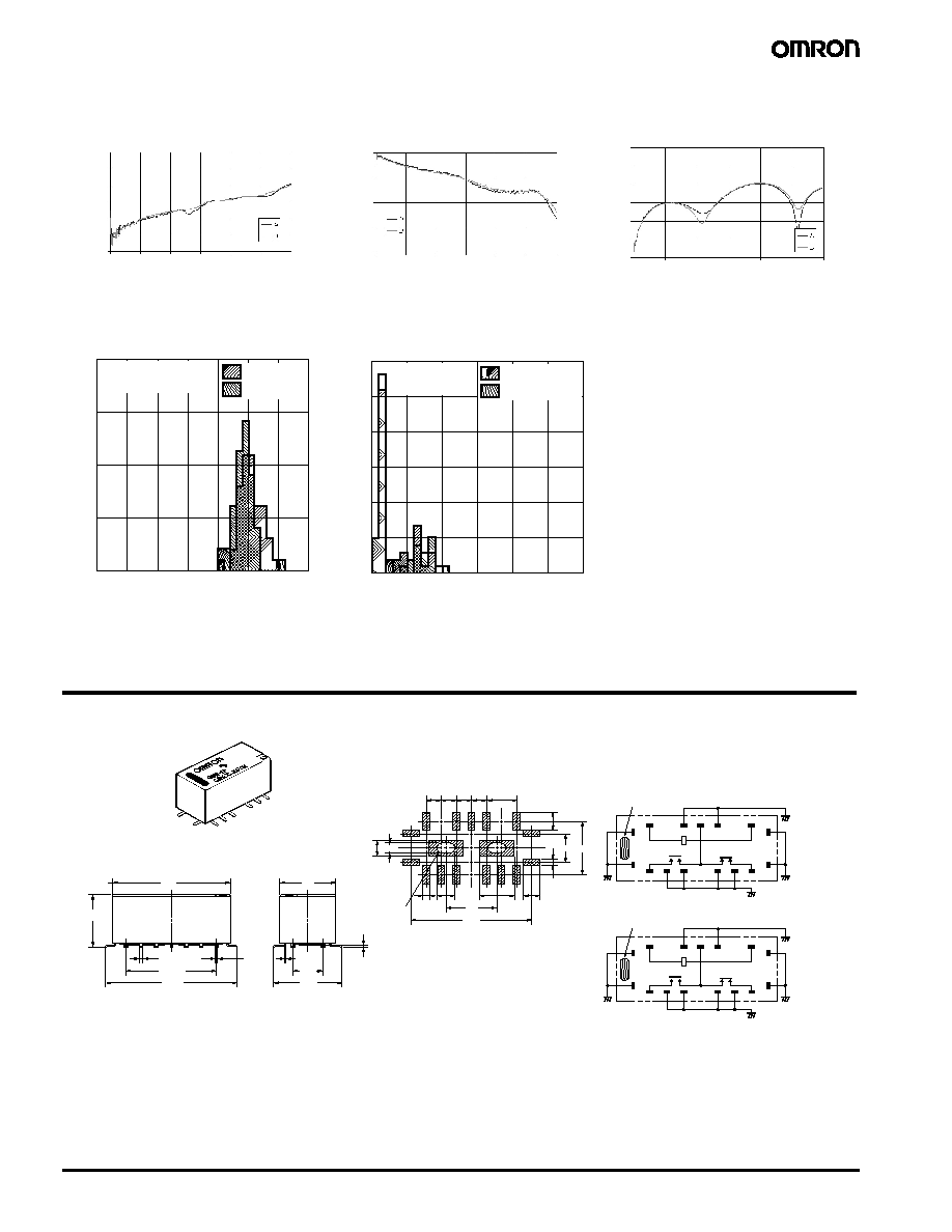
Dimensions
Unit: mm (inch)
Note: Each value has a tolerance of
±0.3 mm.
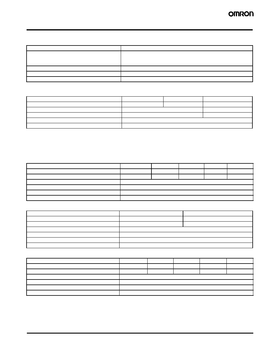
0 1000 2000 3000 4000 5000 6000
0
-20
-40
-60
-80
-100
-120
Isolation (dB)
Frequency (MHz)
0 1000 2000 3000 4000 5000 6000
0
-0.2
-0.4
-0.6
-0.8
Frequency (MHz)
Insertion Loss (dB)
0 1000 2000 3000 4000 5000 6000
0
-10
-20
-30
-40
-50
-60
Frequency (MHz)
Return Loss (dB)
High-frequency Characteristics
(Isolation)
High-frequency Characteristics
(Insertion Loss)
High-frequency Characteristics
(Return Loss)
Must set time
Must reset time
Sample:
G6WK-1P 4.5 VDC
Number of Relays: 20
20
15
10
5
0
0.5
1.0
1.5
2.0
2.5
3.0
3.5
Time (ms)
Number of contacts
Time (ms)
Number of contacts
Must set bounce time
Must reset bounce time
Sample:
G6WK-1P 4.5 VDC
Number of Relays: 20
30
25
20
15
10
5
0
0.5
1.0
1.5
2.0
2.5
3.0
Must Set and Must Reset Time
Distribution (see note).
Must Set and Must Reset Bounce
Time Distribution (see note).
+
17
18
10
8
20
15
14
13
11
1
2
3
5
6
7
+
+
R
S
17
18
10
8
20
15
14
13
11
1
2
3
5
6
7
G6WU-1F
20 9.4
0.2
0.2
5.08
11.6
9.2
Twelve, 0.6
15.24
22.2
Three
0.4
2.7
1.1
Through-hole
5.9
2.8
5.08 9.4
3.2
1.1
8.6
20.4
2.54 2.54 2.54 2.54 5.08
Orientation mark
G6W-1F
Orientation mark
1.8
3
G6W-1F
G6WU-1F
Mounting Pads
(Top View)
Tolerance: ±0.1 mm
Terminal Arrangement/
Internal Connections
(Top View)