 | –≠–ª–µ–∫—Ç—Ä–æ–Ω–Ω—ã–π –∫–æ–º–ø–æ–Ω–µ–Ω—Ç: G6Y | –°–∫–∞—á–∞—Ç—å:  PDF PDF  ZIP ZIP |

High Frequency Relay
G6Y
560
High Frequency Relay
G6Y
Design Based on Micro Strip Line
Technology
H
Isolation characteristics of 65 dB or better at
900 MHz.
H
Effective insertion loss characteristics of 0.2
dB or better at 900 MHz (half the loss of
earlier models).
H
Fully-sealed construction.
H
Improved shock-resistance.
H
Applications include cable TV, cellular
communication, HDTV, fax machine,
satellite communications, pay TV, VCRs,
and test and measurement equipment.
H
Form, fit and function replacement to G5Y
relay with improved characteristics.
H
RoHs Compliant.
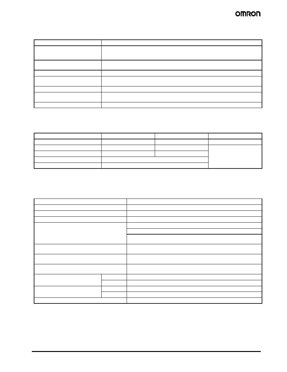
Ordering Information
To order: Select the part number and add the desired coil voltage rating (e.g. G6Y-1-DC12).
Type
Contact form
Construction
Part number
Standard
SPDT
Fully-sealed
G6Y-1
Specifications
J
COIL DATA
Rated
voltage
(VDC)
Rated current
(mA)
Coil resistance
()
Must operate
voltage
Must dropout
voltage
Maximum voltage Power
consumption
( W)
o tage
(VDC)
(
)
( )
% of rated voltage
co su pt o
(mW)
5
40.0
125
75% max.
10% min.
150 at 23∞C
(73∞F)
Approx. 200
6
33.3
180
(73∞F)
130 at 70∞C
pp
9
22.2
405
130 at 70∞C
(158∞F)
12
16.7
720
(158 F)
24
8.3
2,880
Note: The rated current and coil resistance are measured at a coil temperature of 23∞C with a tolerance of ±10%.
The operating characteristics are measured at a coil temperature of 23∞C.
The "Max. allowed voltage" is the maximum voltage that can be applied to the relay coil. It is not the maximum voltage that can be
applied continuously.
561
High Frequency Relay
G6Y
J
CONTACT DATA
Load
Resistive load (p.f. = 1)
Rated load
0.01 A at 30 VAC
0.01 A at 30 VDC
900 MHz, 1 W (See Note.)
Contact material
Au clad
Cu alloy
Max. carry current
0.5 A
Max. operating voltage
30 VAC
30 VDC
Max. operating current
0.5 A
Max. switching capacity
AC10 VA
DC10 W
Min. permissible load
10 mA at 10 mVDC
Note: This value is for a load with VSWR 1.2.
J
HIGH-FREQUENCY CHARACTERISTICS
Item
250 MHz
900 MHz
2.8 GHz
Isolation
80 dB min.
65 dB min.
30 dB min.
Insertion loss
0.5 dB max.
0.5 dB max.
consult factory
VSWR
1.5 max.
1.5 max.
Max. carry power
10 W
Max. operating power
10 W (See Note 2.)
Note: 1. The impedance of the measuring system is 50 . The table above shows preliminary values.
2. This value is for a load with VSWR 1.2.
J
CHARACTERISTICS
Contact resistance (See Note 2.)
100 m max.
Operating time
10 ms max. (approx. 5 ms)
Release time
5 ms max. (approx. 1 ms)
Insulation resistance
100 M min. (at 500 VDC)
Dielectric strength
1,000 VAC, 50/60 Hz for 1 min between coil and contacts
g
500 VAC, 50/60 Hz for 1 min between contacts of same polarity
500 VAC, 50/60 Hz for 1 min between coil and ground and between contacts
and ground
Vibration resistance
Destruction: 10 Hz to 55 Hz, 1.5 mm double amplitude
Malfunction: 10 Hz to 55 Hz, 1.5 mm double amplitude
Shock resistance
Destruction: 1,000 m/s
2
(approx. 100G)
Malfunction: 1,000 m/s
2
(approx. 100G)
Life expectancy
Mechanical: 1,000,000 operations min. (at 1,800 operations/hr.)
Electrical: 300,000 operations min. (under rated load at 1,800 operations/hr.)
Ambient temperature
Operating
--40∞C to 70∞C (--40∞F to 158∞F) with no icing
p
Storage
--40∞C to 70∞C (--40∞F to 158∞F) with no icing
Ambient humidity
Operating
10 to 85%
y
Storage
10 to 85%
Weight
Approx. 5 g
Note: 1. The table above shows preliminary values at room temperature unless otherwise specified.
2. Measurement Conditions: 5 VDC, 100 mA, voltage drop method.

562
High Frequency Relay
G6Y
Engineering Data
J
AMBIENT TEMPERATURE VS.
MAX. ALLOWED VOLTAGE
M
a
x
.
al
l
o
wed
v
ol
t
age
(%
)
Ambient temperature (∞C)
Note: The "Max. allowed voltage" is the maximum voltage that
can be applied to the relay coil. It is not the maximum
voltage that can be applied continuously.
200
180
160
(150)
140
120
100
(130)
0
10
20
30 40
50
60
70
80
90 100
J
CONTACT RELIABILITY TEST
(AMBIENT TEMPERATURE OF 23∞C)
Sample:
G6Y-1, 12 VDC
Quantity:
20 Units
Conditions: Resistive load:
10 mVDC 0.01 mA
Switching frequency:
120 times/minute
N.O. contact
N.C. contact
Contact resistance
Number of operations (◊10
4
)
J
RESISTANCE TO SHOCK
N.O. contact
N.C. contact
Units: m/s
2
Shock direction
1,200 min.
1,200 min.
1,200 min.
1,200 min.
1,200 min.
X
Y
Z'
X'
Y'
Z
X
X'
Y'
Y
Z
Z'
1,000
800
600
400
200
200
400
600
800
1,000
1,200 min.
Test Method: Shock was applied 3 times in each direction
with and without excitation and the level at
which the shock caused malfunction was
measured.
Rating:
500 m/s
2
(approx. 50G)
Quantity Tested: 10 Units
J
HIGH-FREQUENCY CHARACTERISTICS
Measurement Conditions
HP 8753D
Network
Analyzer
Note: The high-frequency characteristics data were
measured using a dedicated circuit board
and actual values will vary depending on the
usage conditions. Check the characteristics
of the actual equipment being used.
Terminals which were not being measured
were terminated with 50
50- Terminator
G6Y-1

563
High Frequency Relay
G6Y
J
ISOLATION CHARACTERISTICS
(AVERAGE VALUES)
I
s
ol
at
i
o
n
(
dB
)
Frequency (MHz)
J
VSWR, RETURN LOSS
CHARACTERISTICS
(AVERAGE VALUES)
Ret
u
rn
l
o
s
s
(dB
)
Frequency (MHz)
Return loss
VSWR
J
BOUNCE TIME DISTRIBUTION
(AMBIENT TEMPERATURE OF 23∞C)
Quant
i
t
y
Time (ms)
Operating bounce time
Release bounce time
Subject: G6Y-1
Quantity: 50 Units
0
1
2
3
4
5
6
7
8
50
40
30
20
10
J
INSERTION LOSS CHARACTERISTICS
(AVERAGE VALUES)
I
n
s
e
rt
i
o
n
l
os
s
(
dB
)
Frequency (MHz)
J
OPERATING RELEASE TIME
DISTRIBUTION
(AMBIENT TEMPERATURE OF 23∞C)
Quant
i
t
y
Sample: G6Y-1
Quantity: 50 Units
Time (ms)
Operating time
Release time
50
40
30
20
10
0
1
2
3
4
5
6
7
8

564
High Frequency Relay
G6Y
Dimensions
Unit: mm (inch)
J
G6Y-1
PCB Dimensions
(Bottom View)
Tolerances: ±0.1 mm.
Six, 1.2-dia. holes
Three, 0.8-dia. holes
(Holes for the coil terminals may also be 1.0.)
Terminal Arrangement/
Internal Connections
(Bottom View)
Note: The shaded and unshaded
parts indicate the product's
directional marks.
20.7max.
(0.81)
15.24
(0.60)
7.62
(0.30)
1.83
(0.07)
15.24
(0.60)
2.54
(0.10)
2.54
(0.10)
2.63
(0.10)
2.05
(0.08)
2.63
(0.10)
11.7max.
(0.46)
7.62
(0.30)
2.05
(0.08)
9.2max.
(0.36)
3
(0.12)
Precautions
J
CORRECT USE
Seal integrity during cleaning will last for 1 minute at 70∞C.
Micro Strip Line Design
∑
It is advantageous to use the Micro Strip Line in high-
frequency transmission circuits because a low-loss trans-
mission can be achieved with this method. By etching the
dielectric base which has copper foil attached to both sides,
the Micro Strip Line will have a concentrated electric field
between the lines and ground, as shown in the following
diagram.
Lines with impedance Z
Ground pattern
Dielectric base
(dielectric constant:
r
)
∑
The characteristic impedance of the lines Z
O
is determined
by the kind of base (dielectric constant), the base's thickness,
and the width of the lines, as expressed in the following
equation.
Z
O
=
377
r
H
W
1+
W
2H
1+In W
H
W: Line width
r
: Effective dielectric constant
H: Dielectric base thickness
The copper foil thickness must be less than H.
∑
The following graph shows this relationship.
Micro Strip (w/h)
Dielectric constant (
r
)
M
i
c
r
o
S
t
r
i
p
i
m
pedanc
e
(
)
∑
For example, when creating 50- lines using a glass epoxy
base with a thickness of 1.6 mm, the above graph will yield a
w/h ratio of 1.7 for a dielectric constant of 4.8. Since the base
thickness is 1.6 mm, the width will be h ◊ 1.7 2.7 mm.
The thickness of the copper foil "t" is ignored in this design
method, but it must be considered because large errors will
occur in extreme cases such as a foil thickness of t w.
In addition, with the Micro Strip Line design, the lines are too
short for the G6Y's intended frequency bandwidths, so we
can ignore conductive losses and the line's attenuation
constant.
∑
The spacing of the Strip Lines and ground pattern should be
comparable to the width of the Strip Lines.

565
High Frequency Relay
G6Y
∑
Design the pattern with the shortest possible distances.
Excessive distances will adversely effect the high-frequency
characteristics.
∑
Spread the ground patterns as widely as possible so that
potential differences are unlikely to develop between the
ground patterns.
∑
To avoid potential short-circuits, do not place the pattern's
leads near the point where the bottom of the Relay attaches
to the board.
Bending the Micro Strip Line
Strip Line with impedance Z
Elbow
Clip the corners
45∞C
When the lines must curve, an elbow can be used as shown in
the diagram. A distance (D) between the lines of approximately
twice the line width is sufficient.
J
EXAMPLES OF MOUNTING DESIGNS
Since this example emphasizes reducing mounting costs,
expensive mounting methods, such as through-hole boards, are
not shown. If such methods are to be used, the characteristics
must be studied carefully, using the actual board configuration.
Using a Double-sided Paper Epoxy Board
When double-sided paper epoxy boards are used, the dielectric
constant will be approximately the same as that of glass epoxy
boards (
r
=4.8).
The width of the Strip Lines for a board with t=1.6 mm is 2.7 mm
for 50 and 1.8 mm for 75 . For a board with t=1.0 mm the
width is 1.7 mm for 50 and 0.8 mm for 75 .
The following diagram shows an example pattern, and the Micro
Strip Lines connected to the contact terminals are formed with
pattern widths derived from the description above. The width
between the Micro Strip Lines and ground patterns are
comparable to the Micro Strip Line width.
There are jumpers between the upper and lower patterns at the
points marked with Xs in the diagram. Improved characteristics
can be obtained with more jumper locations. This method yields
isolation characteristics of 65 dB to 75 dB at 500 MHz and 50 dB
at 900 MHz.
At this point in the diagram the component side is the entire
ground pattern side; but, you must set aside approximately
2.0 mm ◊ 2.0 mm of the pattern for the contact terminals and
coil terminals.
Strip Line
Coil
G6Y
Using a Single-sided Board
When a single-sided board is used, isolation characteristics of
only 60 dB to 70 dB at 200 MHz can be obtained. When high
frequency bands are to be used with a single-sided board, a
metal plate can be placed between the base and Relay and
connected to the ground pattern.
Metal plate
Ground terminals
Metal plate
Printed circuit board
Pattern
G6Y
With this method a metal plate is placed between the Relay and
base and connected to the pattern, as shown in the above
diagram. The important point here is that 3 locations (the G6Y's
ground terminal, the metal plate's bent tabs (A), and the ground
pattern) are soldered together at the same time. This method
combines an inexpensive single-sided board and inexpensive
metal plate to yield the same characteristics as a double-sided
board. Good characteristics are obtained by grounding the G6Y's
ground terminal and metal plate in the same place.
The metal plate must be attached to the base as described here.
From this point, the methods used for Strip Line design are the
same as for the double-sided board.

566
High Frequency Relay
G6Y
Mounting Precautions
Be sure to securely attach the Relay's base surface to the board
during installation. The isolation characteristics will be affected if
the Relay lifts off the board.
As shown in the enlarged illustration of the cross-section of part
A, the G6Y is designed to ensure better high-frequency
characteristics if the stand-off part of the G6Y is in contact with
the ground pattern of the PCB. For this reason, the ground
terminal and stand-off part are electrically connected internally.
Should the through hole electrically connected to the contact
terminal come in contact with the stand-off part, the contact will
be short-circuited with the ground, which may cause an accident.
As a preventive measure, keep at least a distance of 0.3 mm
between the stand-off part and the through hole or land.
For example, if the terminal hole on the PCB is 1 mm in diameter
and the length B shown in the illustration is 1.4 mm, a distance of
0.3 mm or more will be provided between the through hole and
stand-off part.
PCB Mounting
Cross-section of Part A
Part A
Ground
pattern
Stand-off
part
Through
hole
Ground terminal
Contact
terminal
Ground terminal

567
High Frequency Relay
G6Y
MEMO

Terms and Conditions of Sale
1.
Offer; Acceptance. These terms and conditions (these "Terms") are deemed
part of all quotations, acknowledgments, invoices, purchase orders and other
documents, whether electronic or in writing, relating to the sale of products or
services (collectively, the "Products") by Omron Electronic Components LLC
("Seller"). Seller hereby objects to any terms or conditions proposed in
Buyer's purchase order or other documents which are inconsistent with, or in
addition to, these Terms.
2. Prices;
Payment. All prices stated are current, subject to change without
notice by Seller. Buyer agrees to pay the price in effect at time of shipment.
Payments for Products received are due net 30 days unless otherwise stated
in the invoice.
3. Discounts. Cash discounts, if any, will apply only on the net amount of
invoices sent to Buyer after deducting transportation charges, taxes and
duties, and will be allowed only if (i) the invoice is paid according to Seller's
payment terms and (ii) Buyer has no past due amounts owing to Seller.
4. Currencies. If the prices quoted herein are in a currency other than U.S. dol-
lars, Buyer shall make remittance to Seller at the then current exchange rate
most favorable to Seller and which is available on the due date; provided that if
remittance is not made when due, Buyer will convert the amount to U.S. dol-
lars at the then current exchange rate most favorable to Seller available during
the period between the due date and the date remittance is actually made.
5. Governmental
Approvals. Buyer shall be responsible for, and shall bear all
costs involved in, obtaining any government approvals required for the impor-
tation or sale of the Products.
6. Taxes. All taxes, duties and other governmental charges (other than general
real property and income taxes), including any interest or penalties thereon,
imposed directly or indirectly on Seller or required to be collected directly or
indirectly by Seller for the manufacture, production, sale, delivery, importation,
consumption or use of the Products sold hereunder (including customs duties
and sales, excise, use, turnover and license taxes) shall be charged to and
remitted by Buyer to Seller.
7. Financial. If the financial position of Buyer at any time becomes unsatisfactory
to Seller, Seller reserves the right to stop shipments or require satisfactory
security or payment in advance. If Buyer fails to make payment or otherwise
comply with these Terms or any related agreement, Seller may (without liability
and in addition to other remedies) cancel any unshipped portion of Products
sold hereunder and stop any Products in transit until Buyer pays all amounts,
including amounts payable hereunder, whether or not then due, which are
owing to it by Buyer. Buyer shall in any event remain liable for all unpaid
accounts.
8. Cancellation; Etc. Orders are not subject to rescheduling or cancellation
unless Buyer indemnifies Seller fully against all costs or expenses arising in
connection therewith.
9. Force
Majeure. Seller shall not be liable for any delay or failure in delivery
resulting from causes beyond its control, including earthquakes, fires, floods,
strikes or other labor disputes, shortage of labor or materials, accidents to
machinery, acts of sabotage, riots, delay in or lack of transportation or the
requirements of any government authority.
10. Shipping; Delivery. Unless otherwise expressly agreed in writing by Seller:
1. Shipments shall be by a carrier selected by Seller;
2. Such carrier shall act as the agent of Buyer and delivery to such carrier
shall constitute delivery to Buyer;
3. All sales and shipments of Products shall be FOB shipping point (unless
otherwise stated in writing by Seller), at which point title to and all risk of
loss of the Products shall pass from Seller to Buyer, provided that Seller
shall retain a security interest in the Products until the full purchase price is
paid by Buyer;
4. Delivery and shipping dates are estimates only.
5. Seller will package Products as it deems proper for protection against
normal handling and extra charges apply to special conditions.
11. Claims. Any claim by Buyer against Seller for shortage or damage to the
Products occurring before delivery to the carrier must be presented in writing
to Seller within 30 days of receipt of shipment and include the original trans-
portation bill signed by the carrier noting that the carrier received the Products
from Seller in the condition claimed.
12. Warranties. (a) Exclusive Warranty. Seller's exclusive warranty is that the
Products will be free from defects in materials and workmanship for a period of
twelve months from the date of sale by Seller (or such other period expressed
in writing by Seller). Seller disclaims all other warranties, express or implied.
(b) Limitations. SELLER MAKES NO WARRANTY OR REPRESENTATION,
EXPRESS OR IMPLIED, ABOUT NON-INFRINGEMENT, MERCHANTABIL-
ITY OR FITNESS FOR A PARTICULAR PURPOSE OF THE PRODUCTS.
BUYER ACKNOWLEDGES THAT IT ALONE HAS DETERMINED THAT THE
PRODUCTS WILL SUITABLY MEET THE REQUIREMENTS OF THEIR
INTENDED USE. Seller further disclaims all warranties and responsibility of
any type for claims or expenses based on infringement by the Products or oth-
erwise of any intellectual property right. (c) Buyer Remedy. Seller's sole obli-
gation hereunder shall be to replace (in the form originally shipped with Buyer
responsible for labor charges for removal or replacement thereof) the non-
complying Product or, at Seller's election, to repay or credit Buyer an amount
equal to the purchase price of the Product; provided that in no event shall
Seller be responsible for warranty, repair, indemnity or any other claims or
expenses regarding the Products unless Seller's analysis confirms that the
Products were properly handled, stored, installed and maintained and not sub-
ject to contamination, abuse, misuse or inappropriate modification. Return of
any Products by Buyer must be approved in writing by Seller before shipment.
Seller shall not be liable for the suitability or unsuitability or the results from the
use of Products in combination with any electrical or electronic components,
circuits, system assemblies, or any other materials or substances or environ-
ments. Any advice, recommendations or information given orally or in writing
are not to be construed as an amendment or addition to the above warranty.
13. Limitation on Liability; Etc. SELLER SHALL NOT BE LIABLE FOR SPECIAL,
INDIRECT, INCIDENTAL OR CONSEQUENTIAL DAMAGES, LOSS OF
PROFITS OR PRODUCTION OR COMMERCIAL LOSS IN ANY WAY CON-
NECTED WITH THE PRODUCTS, WHETHER SUCH CLAIM IS BASED IN
CONTRACT, WARRANTY, NEGLIGENCE OR STRICT LIABILITY. Further, in
no event shall liability of Seller exceed the individual price of the Product on
which liability is asserted.
14. Indemnities. Buyer shall indemnify and hold harmless Seller, its affiliates and
its employees from and against all liabilities, losses, claims, costs and
expenses (including attorney's fees and expenses) related to any claim, inves-
tigation, litigation or proceeding (whether or not Seller is a party) which arises
or is alleged to arise from Buyer's acts or omissions under these Terms or in
any way with respect to the Products. Without limiting the foregoing, Buyer (at
its own expense) shall indemnify and hold harmless Seller and defend or settle
any action brought against Seller to the extent that it is based on a claim that
any Product made to Buyer specifications infringed intellectual property rights
of another party.
15. Property; Confidentiality. The intellectual property embodied in the Products is
the exclusive property of Seller and its affiliates and Buyer shall not attempt to
duplicate it in any way without the written permission of Seller. Notwithstand-
ing any charges to Buyer for engineering or tooling, all engineering and tooling
shall remain the exclusive property of Seller. All information and materials sup-
plied by Seller to Buyer relating to the Products are confidential and propri-
etary, and Buyer shall limit distribution thereof to its trusted employees and
strictly prevent disclosure to any third party.
16. Miscellaneous. (a) Waiver. No failure or delay by Seller in exercising any right
and no course of dealing between Buyer and Seller shall operate as a waiver
of rights by Seller. (b) Assignment. Buyer may not assign its rights hereunder
without Seller's written consent. (c) Law. These Terms are governed by Illi-
nois law (without regard to conflict of law principles). Federal and state courts
in Illinois shall have exclusive jurisdiction for any dispute hereunder.
(d) Amendment. These Terms constitute the entire agreement between Buyer
and Seller relating to the Products, and no provision may be changed or
waived unless in writing signed by the parties. (e) Severability. If any provision
hereof is rendered ineffective or invalid, such provision shall not invalidate any
other provision. (f) Setoff. Buyer shall have no right to set off any amounts
against the amount owing in respect of this invoice.. (g) Definitions. As used
herein, "including" means "including without limitation".

Certain Precautions on Specifications and Use
1. Suitability for Use. Seller shall not be responsible for conformity with any stan-
dards, codes or regulations which apply to the combination of the Product in
Buyer's application or use of the Product. At Buyer's request, Seller will pro-
vide applicable third party certification documents identifying ratings and limita-
tions of use which apply to the Product. This information by itself is not
sufficient for a complete determination of the suitability of the Product in combi-
nation with the end product, machine, system, or other application or use.
Buyer shall be solely responsible for determining appropriateness of the partic-
ular Product with respect to Buyer's application, product or system. Buyer
shall take application responsibility in all cases but the following is a non-
exhaustive list of applications for which particular attention must be given:
(i) Outdoor use, uses involving potential chemical contamination or electrical
interference, or conditions or uses not described in this document.
(ii) Energy control systems, combustion systems, railroad systems, aviation
systems, medical equipment, amusement machines, vehicles, safety
equipment, and installations subject to
separate industry or government regulations.
(iii)Use in consumer products or any use in significant quantities.
(iv)Systems, machines and equipment that could present a risk to life or
property. Please know and observe all prohibitions of use applicable to this
product.
NEVER USE THE PRODUCT FOR AN APPLICATION INVOLVING SERIOUS
RISK TO LIFE OR PROPERTY WITHOUT ENSURING THAT THE SYSTEM
AS A WHOLE HAS BEEN DESIGNED TO ADDRESS THE RISKS, AND THAT
THE OMRON PRODUCT IS PROPERLY RATED AND INSTALLED FOR THE
INTENDED USE WITHIN THE OVERALL EQUIPMENT OR SYSTEM.
2. Programmable Products. Seller shall not be responsible for the user's
programming of a programmable product, or any consequence thereof.
3. Performance Data. Performance data given in this publication is provided as a
guide for the user in determining suitability and does not constitute a warranty.
It may represent the result of Seller's test conditions, and the users must corre-
late it to actual application requirements. Actual performance is subject to
Seller's Warranty and Limitations of Liability.
4. Change in Specifications. Product specifications and accessories may be
changed at any time based on improvements and other reasons. It is our prac-
tice to change part numbers when published ratings or features are changed,
or when significant construction changes are made. However, some specifica-
tions of the Product may be changed without any notice. When in doubt, spe-
cial part numbers may be assigned to fix or establish key specifications for your
application. Please consult with your Seller representative at any time to con-
firm actual specifications of purchased Product.
5. Errors and Omissions. The information in this publication has been carefully
checked and is believed to be accurate; however, no responsibility is assumed
for clerical, typographical or proofreading errors, or omissions.
6. RoHS Compliance. Where indicated, our products currently comply, to the best
of our knowledge as of the date of this publication, with the requirements of the
European Union's Directive on the Restriction of certain Hazardous Sub-
stances ("RoHS"), although the requirements of RoHS do not take effect until
July 2006. These requirements may be subject to change. Please consult our
website for current information.
OMRON ON-LINE
Global - http://www.omron.com
USA - http://www.components.omron.com
Canada - http://www.omron.ca
Cat. No. JB301-E3-01
Printed in USA
OMRON CANADA, INC.
885 Milner Avenue
Toronto, Ontario M1B 5V8
416-286-6465
OMRON ELECTRONIC
COMPONENTS LLC
55 E. Commerce Drive, Suite B
Schaumburg, IL 60173
847-882-2288
3/05 Specifications subject to change without notice
Complete "Terms and Conditions of Sale" for product purchase and use are on Omron's website
at www.components.omron.com ≠ under the "About Us" tab, in the Legal Matters section.
ALL DIMENSIONS SHOWN ARE IN MILLIMETERS.
To convert millimeters into inches, multiply by 0.03937. To convert grams into ounces, multiply by 0.03527.