 | –≠–ª–µ–∫—Ç—Ä–æ–Ω–Ω—ã–π –∫–æ–º–ø–æ–Ω–µ–Ω—Ç: G7SA | –°–∫–∞—á–∞—Ç—å:  PDF PDF  ZIP ZIP |

D-76
Safety Sensors / Components
Relays with Forcibly Guided Contacts
G7SA
Slim Relays with Forcibly
Guided Contacts Conform-
ing to EN Standards
∑ EN50205 Class A, approved by VDE.
∑ Ideal for use in safety circuits in production machin-
ery.
∑ Four-pole and six-pole Relays are available.
∑ The Relay's terminal arrangement simplifies PWB
pattern design.
∑ Reinforced insulation between inputs and outputs.
Reinforced insulation between some poles.
∑ UL, CSA approval.
Ordering Information
Relays with Forcibly Guided Contacts
Sockets
Model Number Legend
1. NO Contact Poles
2:
DPST-NO
3:
3PST-NO
4:
4PST-NO
5:
5PST-NO
2. NC Contact Poles
1:
SPST-NC
2:
DPST-NC
3:
3PST-NC
Type
Sealing
Poles
Contacts
Rated voltage
Model
Standard
Flux-tight
4 poles
3PST-NO, SPST-NC
24 VDC
G7SA-3A1B
DPST-NO, DPST-NC
G7SA-2A2B
6 poles
5PST-NO, SPST-NC
G7SA-5A1B
4PST-NO, DPST-NC
G7SA-4A2B
3PST-NO, 3PST-NC
G7SA-3A3B
Type
LED indicator
Poles
Rated voltage
Model
Track-mounting
Track mounting and screw mounting possible
No
4 poles
---
P7SA-10F
6 poles
P7SA-14F
Yes
4 poles
24 VDC
P7SA-10F-ND
6 poles
P7SA-14F-ND
Back-mounting
PCB terminals
No
4 poles
---
P7SA-10P
6 poles
P7SA-14P
1 2
G7SA-#A#B
D-77
G7SA
G7S
A
Specifications
Ratings
Coil
Note: 1. The rated current and coil resistance are measured at a coil temperature of 23∞C with tolerances of ±15%.
2. Performance characteristics are based on a coil temperature of 23∞C.
3. The value given for the maximum voltage is for voltages applied instantaneously to the Relay coil
(at an ambient temperature of 23∞C) and not continuously.
Contacts
Rated voltage
Rated current
Coil resistance
Must-operate
voltage
Must-release
voltage
Max. voltage
Power consumption
24 VDC
4 poles: 15 mA
6 poles: 20.8 mA
4 poles: 1,600
W
6 poles: 1,152
W
75% max. (V)
10% min. (V)
110% (V)
4 poles: Approx. 360 mW
6 poles: Approx. 500 mW
Load
Resistive load (cos
f =1)
Rated load
6 A at 250 VAC, 6 A at 30 VDC
Rated carry current
6 A
Max. switching voltage
250 VAC, 125 VDC
Max. switching current
6 A
Max. switching capacity (reference value)
1,500 VA, 180 W
D-78
Safety Sensors / Components
Characteristics
Sockets
Note: 1. If the P7SA-1#F is used between 55 and 85∞C, reduce the continuous current (from 6 A) by 0.1 A for every degree.
2. Measurement conditions: Measurement of the same points as for the dielectric strength at 500 VDC.
3. When using the P7SA-1#F-ND at 24 VDC, use at an ambient operating temperature from -25 to 55∞C.
Relays with Forcibly Guided Contacts
Note: 1. The values listed above are initial values.
2. These times were measured at the rated voltage and an ambient temperature of 23∞C. Contact bounce time is not included.
3. Pole 3 refers to terminals 31-32 or 33-34, pole 4 refers to terminals 43-44, pole 5 refers to terminals 53-54, and pole 6 refers to terminals
63-64.
4. When using a P7SA Socket, the dielectric strength between coil contacts/different poles is 2,500 VAC, 50/60 Hz for 1 min.
5. Min. permissible load is for a switching frequency of 300 operations/min.
6. When operating at a temperature between 70∞C and 85∞C, reduce the rated carry current (6 A at 70∞C or less) by 0.1 A for each degree
above 70∞C.
Model
Continuous current
Dielectric strength
Insulation resistance
P7SA-14#
6 A (see note 1)
2,500 VAC for 1 min. between poles
100 M
W min. (see note 2)
Contact resistance
100 m
W max.
(The contact resistance was measured with 1 A at 5 VDC using the voltage-drop method.)
Operating time (see note 2)
20 ms max.
Response time (see note 2)
10 ms max. (The response time is the time it takes for the normally open contacts to open after
the coil voltage is turned OFF.)
Release time (see note 2)
20 ms max.
Maximum operating
frequency
Mechanical
36,000 operations/hr
Rated load
1,800 operations/hr
Insulation resistance
100 M
W min. (at 500 VDC)
(The insulation resistance was measured with a 500-VDC megger at the same places that the
dielectric strength was measured.)
Dielectric strength (see notes 3, 4)
Between coil contacts/different poles: 4,000 VAC, 50/60 Hz for 1 min
(2,500 VAC between poles 3-4 in 4-pole Relays or poles 3-5, 4-6, and 5-6 in 6-pole Relays.)
Between contacts of same polarity: 1,500 VAC, 50/60 Hz for 1 min
Vibration resistance
10 to 55 Hz, 1.5-mm double amplitude
Shock resistance
Destruction
1,000 m/s
2
Malfunction
100 m/s
2
Durability
Mechanical
10,000,000 operations min. (at approx. 36,000 operations/hr)
Electrical
100,000 operations min. (at the rated load and approx. 1,800 operations/hr)
Min. permissible load (see note 5)
(reference value)
5 VDC, 1 mA
Ambient temperature (see note 6)
Operating:-40∞C to 85∞C (with no icing or condensation)
Storage:-40∞C to 85∞C (with no icing or condensation)
Ambient humidity
Operating:35% to 85%
Storage:35% to 85%
Weight
4 poles: Approx. 22 g
6 poles: Approx. 25 g
Approved standards
EN61810-1 (IEC61810-1), EN50205, UL508, CSA22.2 No. 14
D-79
G7SA
G7S
A
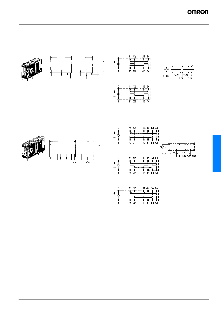
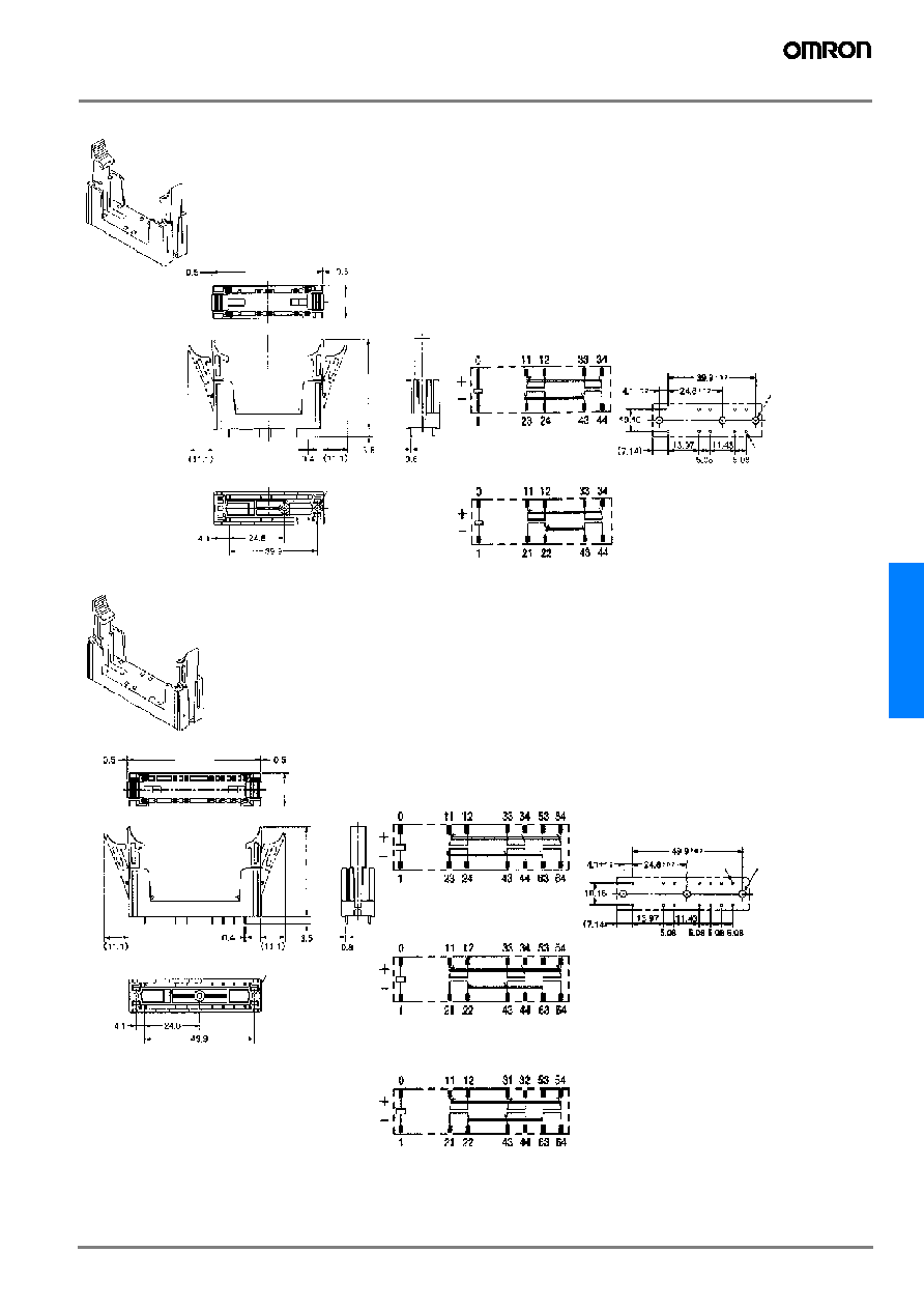
Dimensions
Note: All units are in millimeters unless otherwise indicated. The diagrams are drawn in perspective.
Relays with Forcibly Guided Contacts
0.5
0.5
3.5
1
0.5
0.5
3.5
1
G7SA-2A2B
G7SA-4A2B
G7SA-3A3B
40 max.
13 max.
24 max.
Ten, 1.4 dia.
50 max.
13 max.
24 max.
Fourteen, 1.4 dia.
(
±0.1 tolerance)
(
±0.1 tolerance)
G7SA-3A1B
G7SA-2A2B
G7SA-5A1B
G7SA-4A2B
G7SA-3A3B
Terminal Arrangement/
Internal Connection Diagram
(Bottom View)
G7SA-3A1B
Printed Circuit Board
Design Diagram
(Bottom View)
Note: Terminals 23-24, 33-34, and 43-44
are normally open. Terminals 11-12
and 21-22 are normally closed.
Terminal Arrangement/
Internal Connection Diagram
(Bottom View)
G7SA-5A1B
Printed Circuit Board
Design Diagram
(Bottom View)
Note: Terminals 23-24, 33-34, 53-54, and
63-64 are normally open. Terminals
11-12, 21-22, and 31-32 are
normally closed.
D-80
Safety Sensors / Components
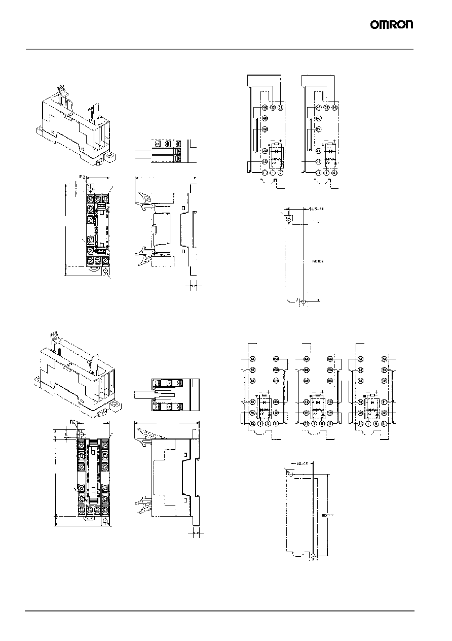
Sockets
6
6
Track-mounting Socket
P7SA-10F, P7SA-10F-ND
Two, 4 dia. or M3.5
4 dia.
22.5 max.
60.5 max.
9 max.
72 max.
9 max.
Track-mounting Socket
P7SA-14F, P7SA-14F-ND
4 dia.
30 max.
60.5 max.
9 max.
72 max.
9 max.
Two, 4 dia. or M3.5
Note: Only the -ND Sockets have LED indicators.
Note: Only the -ND Sockets have LED indicators.
Ten, M3
LED
indicator
Note: The socket is shown with
the finger cover removed.
Terminal Installation/Internal Connection Diagram
(Top View)
G7SA-3A1B
Mounted
G7SA-2A2B
Mounted
* This display circuit is
available only for
"-ND" models.
Note: Terminals 23-24,
33-34, and 43-44
are normally
open. Terminals
11-12 and 21-22
are normally
closed.
Mounting Hole Placement Diagram
(Top View)
LED
indicator
Fourteen,
M3
Note: The socket is shown with the
finger cover removed.
Terminal Arrangement/Internal Connection Diagram
(Top View)
G7SA-5A1B
Mounted
G7SA-4A2B
Mounted
G7SA-3A3B
Mounted
Mounting Hole Placement Diagram
(Top View)
* This display circuit is
available only for
"-ND" models.
Note: Terminals 23-24,
33-34, 43-44,
53-54, and 63-
64 are normally
open. Terminals
11-12, 21-22,
and 31-32 are
normally closed.
G7S
A
D-81
G7SA
P7SA-10P Back-mounting Socket (for PCB)
50 max.
41.5 max.
Ten, 1.1 dia.
15 max.
(
±0.1 tolerance)
Three, 2.6 dia.
(for M3 tapping screws)
Terminal Arrangement/Internal
Connection Diagram
(Bottom View)
Mounting Hole Placement
(Bottom View)
G7SA-3A1B
Mounted
G7SA-2A2B
Mounted
Three, 3.2 dia.
(for M3 tapping screws)
Note: Terminals 23-24, 33-34, and 43-44
are normally open. Terminals 11-12
and 21-22 are normally closed.
P7SA-14P Back-mounting Socket (for PCB)
60 max.
41.5 max.
15 max.
(
±0.1 tolerance)
Three, 2.6 dia.
(for M3 tapping screws)
Terminal Arrangement/Internal
Connection Diagram
(Bottom View)
Mounting Hole Placement
(Bottom View)
G7SA-5A1B
Mounted
G7SA-4A2B
Mounted
G7SA-3A3B
Mounted
Note: Terminals 23-24, 33-34, 43-44,
53-54, and 63-64 are normally
open. Terminals 11-12, 21-22,
and 31-32 are normally closed.
Fourteen,
1.1 dia.
Three, 3.2 dia.
(for M3 tapping
screws)

D-82
Safety Sensors / Components
Precautions
Caution
Do not touch the terminal area of the Relays or the socket terminal
area (charged area) while power is ON. Electric shock will result.
Relays with Forcibly Guided Contacts
A Relay with Forcibly Guided Contacts is a Relay with which a safety
category circuit can be configured.
Wiring
Use one of the following wires to connect to the P7SA-10F/10F-ND/
14F/14F-ND.
Stranded wire:0.75 to 1.5 mm
2
Solid wire:1.0 to 1.5 mm
2
Tighten each screw of the P7SA-10F/10F-ND/14F/14F-ND to a
torque of 0.98 N∑m securely.
Wire the terminals correctly with no mistakes in coil polarity, other-
wise the G7SA will not operate.
Cleaning
The G7SA is not of enclosed construction. Therefore, do not wash
the G7SA with water or detergent.
Forcibly Guided Contacts (from EN50205)
If an NO contact becomes welded, all NC contacts will maintain a
minimum distance of 0.5 mm when the coil is not energized. Like-
wise if an NC contact becomes welded, all NO contacts will maintain
a minimum distance of 0.5 mm when the coil is energized.
Correct Use
Relays with Forcibly Guided Contacts
While the Relay with Forcibly Guided Contacts has the previously
described forcibly guided contact structure, it is basically the same
as an ordinary relay in other respects. Rather than serving to prevent
malfunctions, the forcibly guided contact structure enables another
circuit to detect the condition following a contact weld or other mal-
function. Accordingly, when a contact weld occurs in a Relay with
Forcibly Guided Contacts, depending on the circuit configuration, the
power may not be interrupted, leaving the Relay in a potentially dan-
gerous condition (as shown in Fig. 1.)
To configure the power control circuit to interrupt the power when a
contact weld or other malfunction occurs, and to prevent restarting
until the problem has been eliminated, add another Relay with Forc-
ibly Guided Contacts or similar Relay in combination to provide
redundancy and a self-monitoring function to the circuit (as shown in
Fig. 2).
The G9S/G9SA Safety Relay Unit, which combines Relays such as
the Relay with Forcibly Guided Contacts in order to provide the
above-described functions, is available for this purpose. By connect-
ing a contactor with appropriate input and output to the Safety Relay
Unit, the circuit can be equipped with redundancy and a self-monitor-
ing function.
K1
S1
S2
K1
K1
S1
11
12
21
22
S2
K1
K2
K3
+
-
D
F1
K3 K1
K1
K1
K3 K2
K2
K2
K3
A1 A2 T11 T12
Y1 X1
13
B1
PE T21
T22
14
Fig 1
Fig 2
Power source
Power source