 | –≠–ª–µ–∫—Ç—Ä–æ–Ω–Ω—ã–π –∫–æ–º–ø–æ–Ω–µ–Ω—Ç: G8ND2 | –°–∫–∞—á–∞—Ç—å:  PDF PDF  ZIP ZIP |

Ultra-Miniature Automotive Dual PCB Relay
G8ND2
Ultra-Miniature Automotive Dual PCB Relay
s
Compact size
s
High performance PCB relay
s
25A motor lock load
s
Fully sealed construction
s
Fully automated assembly
s
DPDT ("H" Bridge) contracts
s
Pre-solder as for all terminal
s
PWB pattern design is easy
s
ISO9001/QS9000 series approval
Available Types
G8ND-2 12VDC
G8ND-2S 12VDC
Standard
High Sensitivity
Type
Contact Data
Max Switching Current
Rated Current
Max Switching Voltage
Contact Material
30A
25A Motor load
16V
Silver tin alloy (Cadmium Free)
Coil Ratings
G8ND-2 12VDC
G8ND-2S 12VDC
225
180
Coil Resistance
Type
<7.2
<6.5
Pull in Voltage
Specifications
Temperature Range
Mechanical Life
Electrical Life
Weight
-40 to +85∞C
1,000,000 Operations
100,000 Operations
7.5g
G8ND2
G8ND2
s
Power windows
s
Power door lock
s
Seat adjustment
s
Sunroof
s
Wiper controls
Application Examples
LIFE TEST I (Power window motor: G8ND-2 12VDC)
s
Test item
14VDC-24A/2.6A
130,000
Operations minimum
s
Shift of pick-up drop-out voltage
Operating Voltage
Releasing Voltage
N.O. Contact
Resistance
N.C. Contact
Resistance
LIFE TEST II (Door lock motor: G8ND-2 12VDC)
s
Test item
14VDC-27A
130,000
Operations minimum
Contact
Resistance
(milliohm)
N.O.
Contact
N.C.
Contact
100 or lower
100 or lower
MAX
MAX
MIN
AVE
MIN
AVE
4.20
3.30
3.850
5.00
3.20
4.320
Good
5.62
3.80
4.230
5.10
4.10
4.490
Good
Contact
Resistance
(milliohm)
N.O.
Contact
N.C.
Contact
100 or lower
100 or lower
Structure
No abnormal condition
MAX
MAX
MIN
AVE
MIN
AVE
4.20
3.50
3.669
4.30
3.90
4.120
Good
5.60
3.60
4.290
5.90
4.10
4.360
Good
Structure
No abnormal condition
s
Shift of pick-up drop-out voltage
Operating Voltage
Releasing Voltage
N.O. Contact
Resistance
N.C. Contact
Resistance

G8ND2
G8ND2
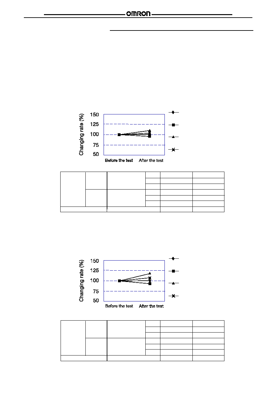
VIBRATION RESISTANCE CHARACTERISTICS
s
Test condition
Frequency: 10Hz-500Hz-10Hz
Acceleration: 45m/s2
Direction of vibration: see right diagram
Detection level: Contacts must not open 1ms or longer
N.O.&N.C. Contacts must not open 1ms longer
SHOCK RESISTANCE CHARACTERISTICS
s
Test condition
Shock application time: 11ms, half-sine wave
Shock direction: see right diagram
Detection level: Contacts must not open 1ms or longer
Z1
Y2
X1
Z2
Y1
X2
N.C. Contact
N.O. Contact
Z
Y
X
Y
X
Z
Z1
Y2
X1
Y1
X2
Z2

G8ND2
G8ND2
REFERENCE DATA (G8ND-2 12VDC)
Distribution of operating voltage and releasing voltage
Ave = 2.76
Ave = 6.14
Ave =
1.17
Ave = 2.70
Distribution of operating time
N.O. contact - Distribution of
contact resistance
N.C. contact - Distribution of
contact resistance
Ave = 3.84
Ave = 4.13
G8ND2
G8ND2
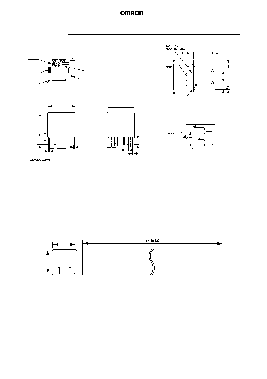
Dimensions
s
Omron PCB relays may be mounted in any
convient location that is dry and not exposed to
excessive dust, S0
2
, H
2
S or organic gases.
0.3
0.1
0.3
0.1
0.3
0.1
0.2
0.3
0.1
0.3
0.1
0.3
0.1
+0.1
0.
+0.1
0.
14. 5 MAX
14. 0 TYP
14.0 MAX
13. 5 TYP
2-1.2
±
0.4+
4-0.6
±
TERMINAL ARRANGEMENT/
INTERNAL CONNECTIONS
(BOTTOM VIEW)
RATED VOLTAGE
MANUFACTURED COUNTRY
TYPE
MARK
LOT NO.
3.5
14. 1 MAX
13.6 TYP
4-0.3
±
2-1.2
±
2-0.3
±
(0.8)
3
9.4
(0.8)
(0.6)
(3.6)
6.4
12.4
(2)
(0.6)
3.2
3.2
3.2
(2)
4-1.6 DIA
MOUNTING HOLES
MOUNTING HOLES
(BOTTOM VIEW)
2-0.3
±
2.5MIN (SOLDERING)
1
8
7
6
5
4
2
3
s
Omron PCB relays may be oriented in any
desired direction. Whenever possible, however,
care should be taken that they are not
subjected to vibration along the direction of
contact movement.
s
Remarks
For use on any of the products, please contact
your sales representative and confirm with spec
sheet and actual usage condition.
We constantly endeavor to enhance the quality
of our products and update our product
offering; therefore, specifications and product
availability are subject to change without notice.
q
Tube carrier
19. OMAX
21. OMAX

LEADERS IN ELECTRONIC COMPONENTS
OMRON Electronic Ltd.
1, Apsley Way,
Staples Corner,
London NW2 7HF
Phone:(020) 8450 4646 Fax:(020) 8450 8087
Cat. No. C-G8ND2-001 In the interest of product improvement, specifications are subject to change without notice.
G8ND2
G8ND2