Document Outline
- PCB Relay G8P
- Ordering Information
- Accessories (Order Separately)
- Specifications
- Coil Ratings
- Contact Ratings
- Characteristics
- Approved Standards
- Engineering Data
- Dimensions
- Open Types
- Plastic-sealed Types
- Precautions

1
PCB Relay
G8P
Small, Low-Cost 30-A Power Relay for
PCB Applications
Small, yet capable of switching up to a 30-A loads.
Inexpensive.
Ideal for home and industrial appliances, HVAC
(heating, ventilating, and air conditioning), and
many other applications.
A variety of contact forms: SPDT, SPST-NO, and
SPST-NC.
UL Class B and F insulation, open and sealed
versions, and dust cover available.
Solder-plated terminals for better solderability.
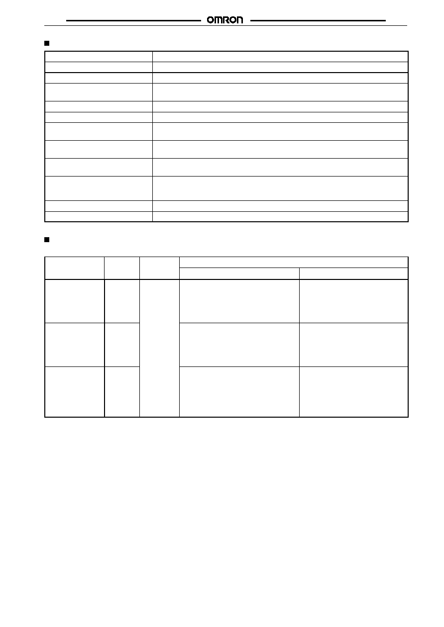
Ordering Information
Contact
form
Standard
Class B
Class F
form
Open
Plastic-sealed
Open
Plastic-sealed
Open
Plastic-sealed
SPST-NO
G8P-1111P-US
G8P-1114P-US
G8P-1111P-BI-US
G8P-1114P-BI-US
G8P-1111P-CF-US
G8P-1114P-CF-US
SPST-NC
G8P-1011P-US
G8P-1014P-US
G8P-1011P-BI-US
G8P-1014P-BI-US
G8P-1011P-CF-US
G8P-1014P-CF-US
SPDT
G8P-111P-US
G8P-114-US
G8P-111P-BI-US
G8P-114P-BI-US
G8P-111P-CF-US
G8P-114P-CF-US
Rated coil voltage
Note: 1. The contacts described above are AgCdO. Ag- and AgSn-contacts are also available. Consult OMRON for details.
2. When ordering, add the rated coil voltage to the model number.
Example: G8P-111P-US 12 VDC
Back

G8P
G8P
2
Model Number Legend:
G8P - - - VDC
1
2
3
4 5
1.
Number of Poles
1:
1 pole
2.
Contact Form
None:SPDT
1:
SPST-NO
0:
SPST-NC
3.
Contact Types
1:
Single button
4.
Enclosure Ratings
1:
Open
4:
Plastic-sealed
5.
Terminals
P:
Straight PCB
6.
UL Insulation Rate
None:Standard
Bl:
Class B
CF:
Class F
7.
Approved Standards
US:
UL/CSA certified
8.
Rated Coil Voltage
5, 6, 9, 12, 15, 18, 24, 48 VDC
6
7
8
Accessories (Order Separately)
Dust cover
G8P-R99-C01
Specifications
Coil Ratings
Rated voltage
5 VDC
6 VDC
9 VDC
12 VDC
15 VDC
18 VDC
24 VDC
48 VDC
Rated current
185 mA
150 mA
93 mA
77 mA
59 mA
47 mA
36 mA
19 mA
Coil resistance
27
40
97
155
256
380
660
2,480
Coil inductance
Armature OFF
0.12
0.16
0.35
0.58
0.99
1.54
2.43
9.41
(H) (ref. value)
Armature ON
0.18
0.26
0.53
0.92
1.56
2.40
4.14
14.7
Must operate voltage
75% max. of rated voltage
Must release voltage
10% min. of rated voltage
Max. voltage
120% of rated voltage
Power consumption
Approx. 900 mW
Note:
The rated current and coil resistance are measured at a coil temperature of 23
∞
C with tolerances of
±
10%.
Contact Ratings
Item
SPST-NO
SPST-NC
SPDT
Load
Resistive load (cos
= 1)
Rated load
30 A at 250 VAC;
20 A at 28 VDC
15 A at 250 VAC;
10 A at 28 VDC
20 A/10 A* at 250 VAC;
20 A/10 A* at 28 VDC
Contact material
AgCdO
Rated carry current
30 A
15 A
20 A/10 A*
Max. switching voltage
250 VAC, 28 VDC
Max. switching current
AC: 30 A, DC: 20 A
AC: 15 A, DC: 10 A
AC: 20 A/10 A, DC: 20 A/10 A*
Max. switching capacity
7,500 VA, 560 W
3,750 VA, 280 W
5,000/2,500 VA, 560/280 W*
Min. permissible load
500 mA at 5 VDC
Note:
*NO contact/NC contact
G8P
G8P
3
Characteristics
Contact resistance
20 m
max.
Operate time
15 ms max. (mean value: approx. 8.4 ms)
Release time
10 ms max. (mean value: approx. 1.6 ms)
Max. operating frequency
Mechanical: 18,000 operations/hr
Electrical: 1,800 operations/hr (under rated load)
Insulation resistance
10 M
min. (at 500 VDC)
Dielectric strength
1,500 VAC, 50/60 Hz for 1 min
Vibration resistance
Destruction:10 to 55 Hz, 1.65-mm double amplitude for 2 hours
Malfunction:10 to 55 Hz, 1.65-mm double amplitude for 5 minutes
Shock resistance
Destruction: 1,000m/s
2
(approx. 100G)
Malfunction: 100 m/s
2
(approx. 10G)
Life expectancy
Mechanical: 10,000,000 operation min. (at 18,000 operations/hr)
Electrical:
See
Engineering Data.
Ambient temperature
Standard types:
≠55
∞
C to 70
∞
C
Class B insulation types: ≠55
∞
C to 85
∞
C
Class F insulation types: ≠55
∞
C to 105
∞
C
Ambient humidity
Operating: 45% to 85%
Weight
Approx. 20 g (G8P-111P), approx. 30 g (G8P-114P)
Note:
The data shown above are initial values.
Approved Standards
UL (File No. E41643)
Type
Contact
form
Coil ratings
Contact ratings
form
UL508-recognized
UL873, UL478, UL1563
G8P-1111P-US
SPST-NO
5 to 48 VDC
15 A, 125 VAC (inductive load)
10 A, 250 VAC (inductive load)
15 A, 28 VDC (resistive load)
1 hp, 125 VAC (motor load)
1 hp, 250 VAC (motor load)
5 A (1,250 W), 250 VAC (tungsten load)
30 A, 250 VAC (inductive load)
1 hp, 125 VAC (motor load)
2 hp, 250 VAC (motor load)
12 A, 277 VAC (inductive load)
G8P-1011P-US
SPST-NC
15 A, 125 VAC (inductive load)
10 A, 250 VAC (inductive load)
10 A, 28 VDC (resistive load)
0.25 hp, 125 VAC (motor load)
0.25 hp, 250 VAC (motor load)
3 A (750 W), 250 VAC (tungsten load)
15 A, 250 VAC (inductive load)
0.25 hp, 125 VAC (motor load)
0.25 hp, 250 VAC (motor load)
6 A, 277 VAC (inductive load)
G8P-111P-US
SPDT
NO/NC
15 A/10 A, 125 VAC (inductive load)
10 A/10 A, 250 VAC (inductive load)
15 A/10 A, 28 VDC (resistive load)
1 hp/0.25 hp, 125 VAC (motor load)
1 hp/0.5 hp, 250 VAC (motor load)
5 A/3 A, 250 VAC (tungsten load)
NO/NC
20 A/10 A, 250 VAC (inductive load)
1 hp/0.25 hp, 125 VAC (motor load)
2 hp/0.5 hp, 250 VAC (motor load)
12 A/6 A, 277 VAC (inductive load)/
UL873

G8P
G8P
4
CSA (File No. LR34815-124)
Type
Contact form
Coil ratings
Contact ratings
G8P-1111P-US
SPST-NO
5 to 48 VDC
6 A, 277 VAC (inductive load)
15 A, 125 VAC (inductive load)
10 A, 250 VAC (inductive load)
15 A, 28 VDC (resistive load)
1 hp, 125 VAC (motor load)
1 hp, 250 VAC (motor load)
5 A, 125 VAC (tungsten load)
5 A, 250 VAC, (tungsten load)
G8P-1011P-US
SPST-NC
3 A, 277 VAC (inductive load)
15 A, 125 VAC (inductive load)
10 A, 250 VAC (inductive load)
10 A, 28 VDC (resistive load)
0.25 hp, 125 VAC (motor load)
0.5 hp, 250 VAC (motor load)
3 A, 125 VAC (tungsten load)
3 A, 250 VAC, (tungsten load)
G8P-111P-US
SPDT
NO/NC
6 A/3 A, 277 VAC (inductive load)
15 A/10 A, 125 VAC (inductive load)
10 A/10 A, 250 VAC (inductive load)
15 A/10 A, 28 VDC (resistive load)
0.5 hp/0.25 hp, 125 VAC (motor load)
1 hp/0.5 hp, 250 VAC (motor load)
5 A/3 A, 125 VAC (tungsten load)
5 A/3 A, 250 VAC, (tungsten load)
Engineering Data
Max. Switching Capacity
SPST-NC
SPDT
Switching current (A)
Switching voltage (V)
AC resistive load
DC resistive load
AC resistive load
DC resistive load
AC resistive load (NO)
AC resistive load (NC)
DC resistive
load (NC)
DC resistive
load (NO)
SPST-NO
Switching current (A)
Switching current (A)
Switching voltage (V)
Switching voltage (V)
Life Expectancy
SPST-NC
SPDT
Switching current (A)
Switching current (A)
Switching current (A)
250-VAC resistive load
28-VDC resistive load
NO contact
28-VDC resistive load
250-VAC resistive load
28-VDC resistive load
NO contact
250-VAC resistive load
NC contact
250-VAC resistive load
SPST-NO
Life expectancy (x10 operations)
3
Life expectancy (x10 operations)
3
Life expectancy (x10 operations)
3

G8P
G8P
5
Dimensions
Note:
All units are in millimeters unless otherwise indicated.
Open Types
Mounting Holes
(Bottom View)
Terminal Arrangement/
Internal Connections
(Bottom View)
G8P-1111P-(BI)-US
15.3
2.5
(9.4)
15.3
(2.8)
3.8
5.1
5.1
3.8
(2)
(3.6)
Three,
2.1
±
0.2-dia.
holes
Two, 1.1
±
0.1-dia. holes
1
2
3
6
5
28.7 max.
3.3
±
0.5
16.9 max.
Terminal Arrangement/
Internal Connections
(Bottom View)
Mounting Holes
(Bottom View)
G8P-1011P-(BI)-US
22.9
2.5
(1.8)
15.3
(2.8)
3.8
5.1
5.1
3.8
(2)
(3.6)
Two, 1.1
±
0.1-dia. holes
Three,
2.1
±
0.2-dia.
holes
1
2
4
6
5
3.3
±
0.5
28.7 max.

G8P
G8P
6
Terminal Arrangement/
Internal Connections
(Bottom View)
Mounting Holes
(Bottom View)
G8P-111P-(BI)-US
15.3
2.5
(1.8)
15.3
(2.8)
3.8
5.1
5.1
3.8
(2)
(3.6)
Two, 1.1
±
0.1-dia. holes
Four,
2.1
±
0.2-dia.
holes
7.6
5
1
2
3
4
6
3.3
±
0.5
28.7 max.
Plastic-sealed Types
Terminal Arrangement/
Internal Connections
(Bottom View)
Mounting Holes
(Bottom View)
G8P-1114P-(BI)-US
15.3
2.5
10.8
15.3
(4.8)
3.8
5.1
5.1
3.8
(4.3)
Three,
2.1
±
0.2-dia.
holes
Two, 1.1
±
0.1-dia. holes
(5.4)
6
1
2
3
5
17.8
3.7
±
0.5

G8P
G8P
7
Terminal Arrangement/
Internal Connections
(Bottom View)
Mounting Holes
(Bottom View)
G8P-1014P-(BI)-US
22.9
2.5
3.2
15.3
(4.8)
3.8
5.1
5.1
3.8
(4.3)
(5.4)
Three,
2.1
±
0.2-dia.
holes
Two, 1.1
±
0.1-dia. holes
5
1
2
6
4
17.8
3.7
±
0.5

G8P
G8P
8
Terminal Arrangement/
Internal Connections
(Bottom View)
Mounting Holes
(Bottom View)
G8P-114P-(BI)-US
Dust Cover
G8P-R99-C01
15.3
2.5
3.2
15.3
(4.8)
3.8
5.1
5.1
3.8
(4.3)
(5.4)
Four,
2.1
±
0.2-dia.
holes
Two, 1.1
±
0.1-dia. holes
7.6
1
2
6
5
3
4
17.8
3.7
±
0.5
Precautions
Sealed Relays
Remove the vent hole tape seal from the cover after all soldering
and cleaning have been completed to allow air circulation within
sealed G8P Relays.
ALL DIMENSIONS SHOWN ARE IN MILLIMETERS.
To convert millimeters into inches, multiply by 0.03937. To convert grams into ounces, multiply by 0.03527.
Cat. No. K40-E1-5