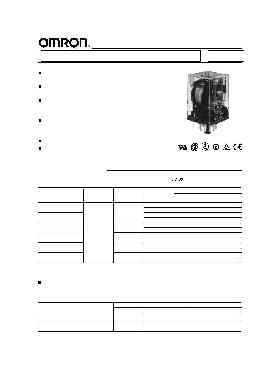
Exceptionally reliable general purpose
relay
Long life (minimum 100,000 electrical
operations) assured by silver contacts
Built-in operation indicator (mechanical,
LED), diode surge suppression, Varistor
surge suppression
The contact operation can be easily
checked by mechanical indicator and/or
push-to-test button options
Conforms to CENELEC standards
VDE approved versions available
General Purpose Relay
MK
Ordering Information
To Order: Select the part number and add the desired coil voltage rating (e.g., MK3P5-S-
).
Note: 1. Reverse polarity versions available on DC coil types. Consult your OMRON representative for further information.
2. VDE approved versions are available. Consult your OMRON representative for further information.
Part number
Mechanical
Mechanical indicator
Type
Terminal
Coil
Contact form
indicator
& push-to-test button
Standard
Plug-in
AC/DC
DPDT
MK2P-I
MK2P-S
3PDT
MK3P-5-I
MK3P-5-S
LED indicator
DPDT
MK2PN-I
MK2PN-S
3PDT
MK3PN-5-I
MK3PN-5-S
LED indicator and diode
DC
DPDT
MK2PND-I
MK2PND-S
3PDT
MK3PND-5-I
MK3PND-5-S
LED indicator and varistor
AC
DPDT
MK2PNV-I
MK2PNV-S
3PDT
MK3PNV-5-I
MK3PNV-5-S
Diode
DC
DPDT
MK2PD-I
MK2PD-S
3PDT
MK3PD-5-I
MK3PD-5-S
Varistor
AC
DPDT
MK2PV-I
MK2PV-S
3PDT
MK3PV-5-I
MK3PV-5-S
ACCESSORIES
(Order separately)
To Order: Select the appropriate part numbers for sockets, clips, and mounting tracks (if required) from the available types chart.
Track mounted sockets
Part number
Relay type
Socket
Relay hold-down clip
Mounting track/end plate
SPDT
PF083A-E
PFC-A1
PFP-100N or PFP-50N and
DPDT
PFP-M (end plate)
3PDT
PF113A-E
PFC-A1
PFP-100N or PFP-50N and
PFP-M (end plate)

2
MK
MK
COIL DATA
Note: 1. The rated current and coil resistance are measured at a coil temperature of 23 C (73 F) with a tolerance of 15% for DC
rated current and +15%, -20% for AC rated current.
2. The rated current is reference value.
3. Performance characteristic data are measured at a coil temperature of 23 C (73 F).
4. For models with the LED indicator built-in, add an LED current of approximately 0 thru 5 mA to the rated current.
Specifications
CONTACT DATA
Resistive load (p.f. = 1)
Load
2 Pole
3 Pole
Inductive load (p.f. = 0.4)
Rated load
10 A at 250 VAC
10 A at 120 VAC
7 A at 250 VAC
10 A at 28 VDC
10 A at 28 VDC
10 A at 250 VAC
Contact material
Ag
Carry current
10 A
Max. operating voltage
250 VAC, 250 VDC
Max. operating current
10 A
Max. switching capacity
2,500 VA
2,500 VA/1,250 VA (NO/NC contacts)
1,750 VA
280 W
280 W
Min. permissible load
10 mA at 1 VDC
Rated
Rated
Coil
Coil inductance
Pick-up
Dropout
Maximum
Power
voltage
current (mA)
resistance
(Ref. value) (H)
voltage
voltage
voltage
consumption
(VAC)
(at 60 Hz)
( )
Armature OFF
Armature ON
% of rated voltage
(mW)
6
360
3.9
0.0423
0.0201
80% max.
30% min.
110% max. Approx.
12
180
16.3
0.3270
0.1666
Approx.
(at 60 Hz)
2.3 VA
24
88.0
68.0
0.6940
0.3760
2.7 VA
25% min.
(at 60 Hz)
50
39.0
338
3.195
1.530
(at 50 Hz)
Approx.
110
21.0
1240
13.45
7.32
2.7 VA
120
18.0
1578
15.04
7.19
(at 50 Hz)
220
11.0
5090
49.73
27.02
240
9.2
6737
58.62
32.07
Rated
Rated
Coil
Coil inductance
Pick-up
Dropout
Maximum
Power
voltage
current (mA)
resistance
(Ref. value) (H)
voltage
voltage
voltage
consumption
(VDC)
(at 60 Hz)
( )
Armature OFF
Armature ON
% of rated voltage
(mW)
6
255
23.5
0.206
0.106
80% max.
15% min.
110% max. Approx.
12
126
95
0.963
0.449
Approx.
1.5 W
24
56
430
4.915
2.478
2.7 VA
48
29.5
1630
16.685
10.487
110
15.1
7300
80.2
42.6
AC
DC
Back connecting sockets
Part number
Relay type
Socket
Relay hold-down clip
SPDT
PL08
PLC-E
DPDT
PLE08-0
PLC-10
PL08-Q
PLC-E
3PDT
PL11
PLC-E
PLE11-0
PLC-10
PL11-Q
PLC-E
ACCESSORIES
(continued)
3
MK
MK
CHARACTERISTICS
Contact resistance
50 m max.
Operate time
AC: 20 ms max. DC: 30 ms max.
Release time
20 ms max.
Operating frequency
Mechanical
18,000 operations/hour
Electrical
1,800 operations/hour (under rated load)
Insulation resistance
100 M min. (at 500 VDC)
Dielectric strength
2,500 VAC, 50/60 Hz for 1 minute between coil and contacts
1,000 VAC, 50/60 Hz for 1 minute between contacts of same poles, between
terminals of the same polarity
2,500 VAC, 50/60 Hz for 1 minute between current-carrying parts, noncurrent-
carrying parts, and terminals of opposite polarity
Vibration
Mechanical durability
10 to 55 Hz, 1.50 mm (0.06 in) double amplitude
Malfunction durability
10 to 55 Hz, 1.00 mm (0.04 in) double amplitude
Shock
Mechanical durability
1,000 m/s
2
(approx. 100 G)
Malfunction durability
100 m/s
2
(approx. 10 G)
Ambient temperature
Operation: -10 to 40 C (14 to 104 F)
Humidity
35 to 85% RH
Service Life
Mechanical
10 million operations min. (at operating frequency of 18,000 operations/hour)
Electrical
100,000 operations at rated load (at operating frequency of 1,800 operations/hour)
Weight
Approx. 0.85 g (3.0 oz)
Note: Data shown are of initial value.
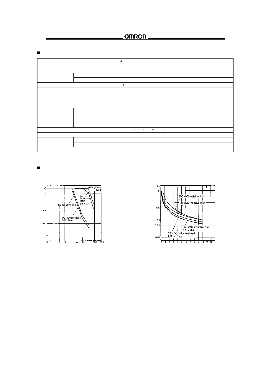
CHARACTERISTIC DATA
Maximum switching capacity
Electrical service life
MK2P-S, MK3P5-S
MK2P-S, MK3P5-S
Rated operating voltage (V)
R
a
t
e
d
o
p
e
r
a
t
i
n
g
c
u
r
r
e
n
t
(
A
)
Rated operating current (A)
S
e
r
v
i
c
e
l
i
f
e
(
x
1
0
6
o
p
e
r
a
t
i
o
n
s
)

4
MK
MK
TERMINAL ARRANGEMENT
(Bottom view)
Standard type (AC/DC coil)
LED indicator type (AC coil)
MK2P-I, S
MK3P5-I, -S
MK2PN-I, -S
MK3PN-5-I, -S
LED indicator type (DC coil)
Diode type (DC coil)
MK2PN-I, -S
MK3PN-5-I, -S
MK2PD-I, -S
MK3PD-5-I, -S
Varistor type (AC coil)
LED indicator and diode type (DC coil)
MK2PV-I, -S
MK3PV-5-I, -S
MK2PND-I, -S
MK3PND-5-I, -S
LED indicator and Varistor type (AC coil)
MK2PNV-I, -S
MK3PNV-5-I, -S
Unit: mm (inch)
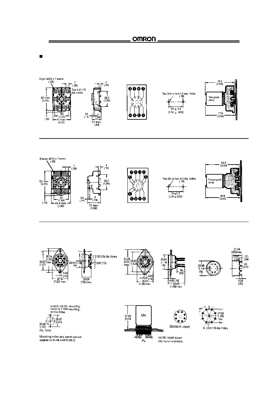
Dimensions
RELAYS
5
MK
MK
Track mounted socket
PF083A-E (conforming to DIN EN 50022)
Terminal
Mounting
Mounting dimensions
arrangement
holes
of relay with socket
Note: Model PF083A-E can be used as a front connecting socket.
Track mounted socket
PF113A-E (conforming to DIN EN 50022)
Terminal
Mounting
Mounting dimensions
arrangement
holes
of relay with socket
Note: Model PF113A-E can be used as a front connecting socket.
Back connecting socket
Printed circuit
MK2 sockets (8 pin)
board socket
PL08 (UL File No. E87929)
PL08-Q
PLE08-0
Solder terminals
Wire wrap terminals
Mounting holes
PL08 type sockets and MK2 relay
Recommended PCB layout
PL08
Total height dimension
PLE08-0
ACCESSORIES