
Switch mode Power Supply
S82J
L-79
Power
Supplies
Switch mode Power Supply
S82J
Compact and Economical Switch mode Power Supplies with Capacities Up to 600 W
DIN Track Mounting Bracket Type Now Available
∑ Power range from 10 W up to 600 W.
∑ Output Voltages: 5 V, 12 V, 15 V, or 24 V.
∑ Mounting bracket provided for mounting to control panels.
∑ Maintenance-free up to 300 W due to natural ventilation.
∑ Protection-ON alarm indicator shows valuable protection functions in action (300-/600-W models).
∑ Conforms to EMC standards: EN50081-2 and EN50082-2.
∑ With an external filter, achieves conformance to EN50081-1 for universal usage on EMI (300-/600-W models).
∑ Finger protection terminal block to meet VDE0106/P100
∑ Class 2 approved 10-W, 25-W (except for 5-V output), and 50-W (only for 24-V output) models.
∑ UL508 approved. All models can be used at full load in UL508A industrial control panel applications.
∑ Approved by UL/CSA standards, EN60950, and EN50178 (VDE0160).
∑ Six-language instruction manual provided. (English, French, German, Italian, Spanish, and Japanese)
Model Number Structure
I Model Number Legend
S82J
Covered Type
Open-frame Type
Enclosure Type
<10 W to 150 W>
∑ 100 to 240-VAC input
∑ 100 or 200 VAC (selected automatically)
(100-W 5-/12-/15-V output, 150-W models)
<10 W to 150 W>
∑ 100 to 240-VAC input
∑ 100 or 200 VAC (selected automatically)
(100-W 5-/12-/15-V output, 150-W models)
<300/600 W>
∑ 100 or 200 VAC (selectable)
S82J -
1
3
2
4
1. Power Ratings
010: 10
W
025: 25
W
050: 50
W
100: 100
W
150: 150
W
300: 300
W
600: 600
W
4. Mounting Bracket
None: Front-mounting Bracket Type
D:
DIN Track Mounting Bracket Type
2. Output Voltage
05: 5
V
12: 12
V
15: 15
V
24: 24
V
3. Configuration
A:
Open-frame type, front terminals
B:
Open-frame type, top terminals
C:
Open-frame type, connector
D:
Covered type, front terminals
E:
Covered type, top terminals
F:
Covered type, connector
N:
Without Mounting Bracket
None: Enclosure type, front terminals with
Mounting Bracket

L-80
Switch mode Power Supply
S82J
Ordering Information
I Front-mounting Bracket Type
Configuration
Input Voltage
Power
ratings
Output
voltage
Output
current
Front terminals
Top terminals
Connector
Open-frame type 100 to 240 VAC 10 W
5 V
2 A
S82J-01005A
---
---
12 V
1 A
S82J-01012A
---
---
15 V
0.7 A
S82J-01015A
---
---
24 V
0.5 A
S82J-01024A
---
---
25 W
5 V
5 A
S82J-02505A
---
---
12 V
2.1 A
S82J-02512A
---
---
15 V
1.7 A
S82J-02515A
---
---
24 V
1.1 A
S82J-02524A
---
---
50 W
5 V
10 A
S82J-05005A
---
---
12 V
4.2 A
S82J-05012A
---
---
24 V
2.1 A
S82J-05024A
---
---
100 or 200 VAC
(selected
automatically)
100 W
5 V
20 A
S82J-10005A
S82J-10005B
S82J-10005C
12 V
8.5 A
S82J-10012A
S82J-10012B
S82J-10012C
15 V
7 A
S82J-10015A
S82J-10015B
S82J-10015C
100 to 240 VAC
24 V
4.5 A
S82J-10024A
---
---
100 or 200 VAC
(selected
automatically)
150 W
24 V
6.5 A
S82J-15024A
S82J-15024B
S82J-15024C
Covered type
100 to 240 VAC 10 W
5 V
2 A
S82J-01005D
---
---
12 V
1 A
S82J-01012D
---
---
15 V
0.7 A
S82J-01015D
---
---
24 V
0.5 A
S82J-01024D
---
---
25 W
5 V
5 A
S82J-02505D
---
---
12 V
2.1 A
S82J-02512D
---
---
15 V
1.7 A
S82J-02515D
---
---
24 V
1.1 A
S82J-02524D
---
---
50 W
5 V
10 A
S82J-05005D
---
---
12 V
4.2 A
S82J-05012D
---
---
24 V
2.1 A
S82J-05024D
---
---
100 or 200 VAC
(selected
automatically)
100 W
5 V
20 A
S82J-10005D
S82J-10005E
S82J-10005F
12 V
8.5 A
S82J-10012D
S82J-10012E
S82J-10012F
15 V
7 A
S82J-10015D
S82J-10015E
S82J-10015F
100 to 240 VAC
24 V
4.5 A
S82J-10024D
---
---
100 or 200 VAC
(selected
automatically)
150 W
24 V
6.5 A
S82J-15024D
S82J-15024E
S82J-15024F
100 or 200 VAC
(selectable)
300 W
24 V
14 A
S82J-30024
---
---
S82J-30024N
---
---
600 W
27 A
S82J-60024
---
---
S82J-60024N
---
---

Switch mode Power Supply
S82J
L-81
Power
Supplies
I DIN Track Mounting Bracket Type
Configuration
Input Voltage
Power
ratings
Output
voltage
Output
current
Front terminals
Top terminals
Connector
Open-frame type 100 to 240 VAC 10 W
5 V
2 A
S82J-01005AD
---
---
12 V
1 A
S82J-01012AD
---
---
15 V
0.7 A
S82J-01015AD
---
---
24 V
0.5 A
S82J-01024AD
---
---
25 W
5 V
5 A
S82J-02505AD
---
---
12 V
2.1 A
S82J-02512AD
---
---
15 V
1.7 A
S82J-02515AD
---
---
24 V
1.1 A
S82J-02524AD
---
---
50 W
5 V
10 A
S82J-05005AD
---
---
12 V
4.2 A
S82J-05012AD
---
---
24 V
2.1 A
S82J-05024AD
---
---
100 or 200 VAC
(selected
automatically)
100 W
5 V
20 A
S82J-10005AD
S82J-10005BD
S82J-10005CD
12 V
8.5 A
S82J-10012AD
S82J-10012BD
S82J-10012CD
15 V
7 A
S82J-10015AD
S82J-10015BD
S82J-10015CD
100 to 240 VAC
24 V
4.5 A
S82J-10024AD
---
---
100 or 200 VAC
(selected
automatically)
150 W
24 V
6.5 A
S82J-15024AD
S82J-15024BD
S82J-15024CD
Covered type
100 to 240 VAC 10 W
5 V
2 A
S82J-01005DD
---
---
12 V
1 A
S82J-01012DD
---
---
15 V
0.7 A
S82J-01015DD
---
---
24 V
0.5 A
S82J-01024DD
---
---
25 W
5 V
5 A
S82J-02505DD
---
---
12 V
2.1 A
S82J-02512DD
---
---
15 V
1.7 A
S82J-02515DD
---
---
24 V
1.1 A
S82J-02524DD
---
---
50 W
5 V
10 A
S82J-05005DD
---
---
12 V
4.2 A
S82J-05012DD
---
---
24 V
2.1 A
S82J-05024DD
---
---
100 or 200 VAC
(selected
automatically)
100 W
5 V
20 A
S82J-10005DD
S82J-10005ED
S82J-10005FD
12 V
8.5 A
S82J-10012DD
S82J-10012ED
S82J-10012FD
15 V
7 A
S82J-10015DD
S82J-10015ED
S82J-10015FD
100 to 240 VAC
24 V
4.5 A
S82J-10024DD
---
---
100 or 200 VAC
(selected
automatically)
150 W
24 V
6.5 A
S82J-15024DD
S82J-15024ED
S82J-15024FD

L-82
Switch mode Power Supply
S82J
Switching Power Supply
S82J
L-83
Power
Supplies
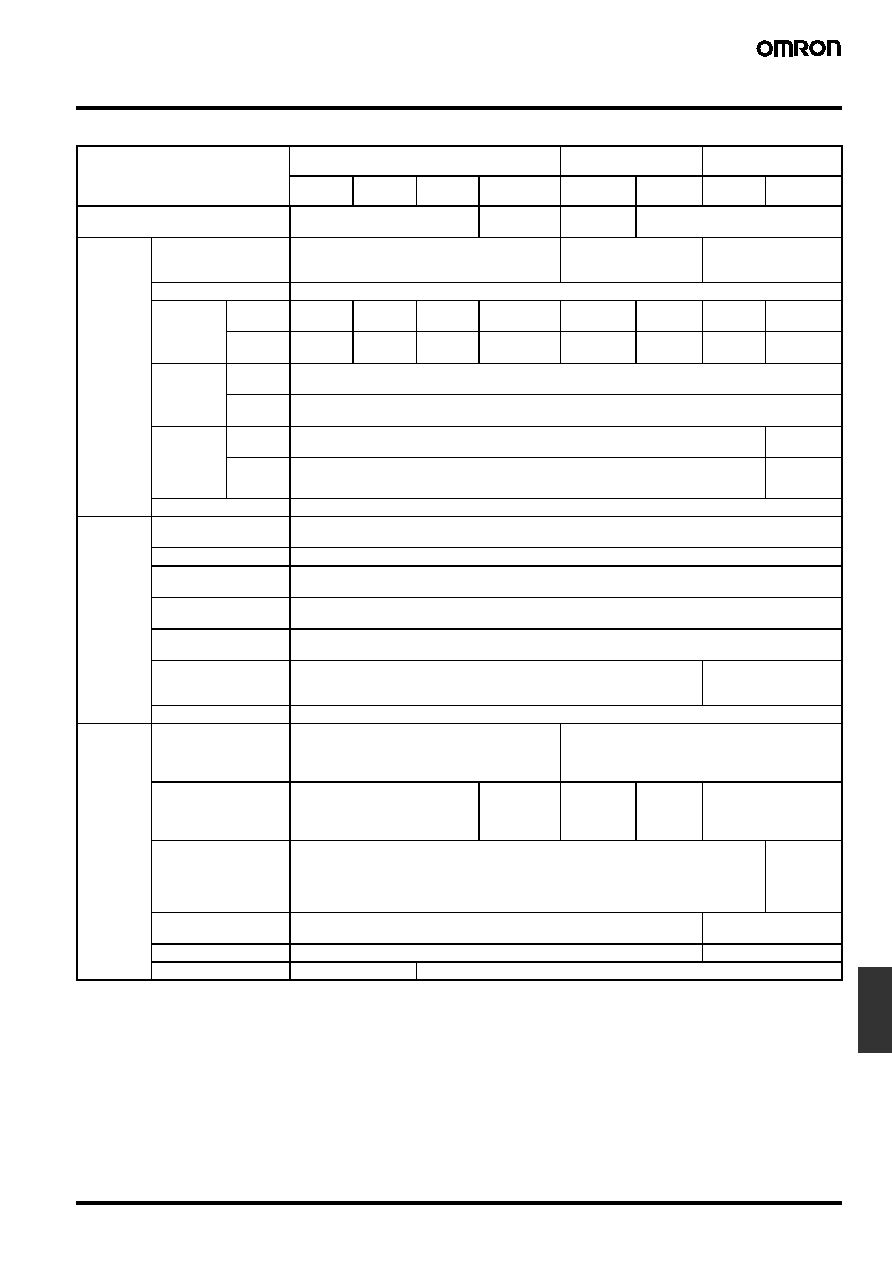
Specifications
I Ratings/Characteristics
Item
100 to 240 VAC input
100 or 200 VAC
(selected automatically)
100 or 200 VAC
(selectable)
10 W
25 W
50 W
100 W (24 V)
100 W
(5, 12, 15 V)
150 W
300 W
600 W
Efficiency (typical)
67% min. (77% min. for 50-W, 24-
V models)
83% min.
75% min.
82% min.
Input
Voltage
100 to 240 VAC (85 to 264 VAC)
110 to 170 VDC (set the terminal (L) to + side)
(10 and 25 W only) (See note 1.)
100 (85 to 132) or 200
(170 to 264) VAC
(selected automatically)
100 (85 to 132) or 200
(170 to 253) VAC
(selectable)
Frequency
50/60 Hz (47 to 450 Hz)
Current
(See note
2.)
100 VAC
input
0.35 A
max.
0.8 A max. 1.4 A max. 2.5 A max.
2.5 A max.
3.5 A max. 8 A max.
14 A max.
200 VAC
input
0.3 A max. 0.6 A max. 0.8 A max. 1.5 A max.
1.4 A max.
2.1 A max. 4 A max.
7 A max.
Leakage
current
(See note
2.)
100 VAC
input
0.5 mA max.
200 VAC
input
1 mA max.
Inrush cur-
rent (25
∞C,
cold start)
(See note
2.)
100 VAC
input
25 A max.
30 A max.
200 VAC
input
50 A max.
60 A max.
Noise filter
Yes
Output
(See note
3.)
Voltage adjustment
range
±10% (adjustable with variable resistor (V. ADJ))
Ripple (See note 2.)
2% (p-p) max.
Input variation
influence
0.4% max.
Load variation
influence
0.8% max. (with rated input, 10% to 100% load)
Temperature variation
influence
0.05%/
∞C max. (with rated input and output)
Startup time
500 ms max. (up to 90% of output voltage at rated input and output)
300 ms max. (up to 90%
of output voltage at rated
input and output)
Hold time (See note 2.) 20 ms min.
Additional
function
Overload protection
105% to 160% of rated load current, inverted L
drop/intermittent operation type, automatic reset
105% min. of rated load current, inverted L drop
type, automatic reset (For the 600-W model, the cir-
cuit will be shut OFF when the overload exceeds 5
±3 s. Protection-ON alarm indicator lit (See note 4.))
Overvoltage
protection (See note 5.)
No
Yes
(See note 5.)
Yes (5-V out-
put models
only) (See
note 5.)
No
Yes, protection-ON alarm
indicator lit (See note 4.)
Overheat protection
No
Yes,
protection-
ON alarm
indicator lit
(See note 4.)
Protection-ON alarm
indicator
No
Yes (color, red)
Parallel operation
No
Yes, 5 units max.
Series operation
No
Yes

L-84
Switching Power Supply
S82J
Note: 1. DC inputs not included in safety standard approvals.
2. At 100% load for rated input voltage (100 VAC or 200 VAC).
3. The output specification is defined at the power supply output terminals.
4. For resetting, turn OFF the power supply, leave for more than three minutes (90 seconds min. for the 300-W models), and then turn ON
the power supply.
5. For resetting, turn OFF the power supply, leave for more than one minute, and then turn ON the power supply.
6. To ensure the Emission Enclosure rating ferrite ring cores (recommended model: S82Y-JC-T) should be used on all cabling.
7. To ensure the Emission AC Mains rating for EN50081-1 (only for 200-VAC input), a noise filter (recommended models: S82Y-JF3-N for
300-W, S82Y-JF6-N for 600-W) should be used on the input lines.
8. With UL508, 150-W connector type has "Recognized" approval.
9. The weight indicated is the weight of the open-frame type. (Includes the covers for 300-W and 600-W models)
10. Class 2 approved for 10-W, 25-W (except for 5-V output), and 50-W (only for 24-V output) models.
I Reference Value
Other
Ambient temperature
Operating: See the derating curve in the Engineering Data section.
Storage:
-25 to 65∞C (with no condensation and icing)
Ambient humidity
Operating: 25% to 85%
Storage:
25% to 90%
Dielectric strength
3.0 kVAC, 50/60 Hz for 1 min (between all inputs and all outputs)
2.2 kVAC, 50/60 Hz for 1 min (between all inputs and GR terminal)
1.0 kVAC, 50/60 Hz for 1 min (between all outputs and GR terminal)
Insulation resistance
100 M
min. (between all outputs and all inputs/GR terminals at 500 VDC)
Vibration resistance
10 to 55 Hz, 0.375-mm double amplitude for 2 h each in X, Y, and Z directions
Shock resistance
300 m/s
2
, 3 times each in
±X, ±Y, and ±Z directions
Terminal screw
tightening
0.74 N∑m
1.08 N∑m
Output indicator
Yes (green)
Electromagnetic
interference
(See note 2.)
Conforms to FCC Class A
EMC
Emission Enclosure:
EN55011 class A
Emission AC Mains:
EN55011 class A
Immunity ESD:
EN61000-4-2: 4 kV contact discharge (level 2)
8 kV air discharge (level 3)
Immunity RF-interference:
ENV50140:
10 Vm (80 MHz to 1 GHz) (level 3)
Immunity Conducted Disturbance: ENV50141:
10 V (0.5 to 80 MHz) (level 3)
Immunity Burst:
EN61000-4-4: 2 kV power-line (level 3)
2 kV output line (level 4)
EMC standards
Conforms to EN50081-2 and EN50082-2
Conforms to EN50081-2
and EN50082-2 (See
note 6.)
With noise filter, confirms
to EN50081-1 (See note
6 and 7.)
Approved
standards
UL
UL508 (Listing), 1950, Class 2
(per UL1310) (See note 10.)
UL508 (Listing), 1012, 1950 (See note 8.) UL508/1012
CSA
CSA C22.2 No. 14, No. 950,
Class 2 (See note 10.)
CSA C22.2 No. 14, No. 950
CSA EB1402C
VDE
EN50178 (VDE0160) and EN60950
Terminal types (only terminal part): VDE0106/P100
Weight (See note 9.)
250 g
max.
350 g
max.
400 g
max.
500 g max.
1,000 g max.
2,000 g
max.
2,500 g max.
Item
100 to 240 VAC input
100 or 200 VAC
(selected automatically)
100 or 200 VAC
(selectable)
10 W
25 W
50 W
100 W (24 V)
100 W
(5, 12, 15 V)
150 W
300 W
600 W
Item
Value
Definition
Reliability (MTBF)
135,000 hours min.
MTBF stands for Mean Time Between Failures, which is calculated according to the probabil-
ity of accidental device failures, and indicates reliability of devices. Therefore, it does not nec-
essarily represent a life of the product.
Life expectancy
10 yrs. min.
The life expectancy indicates average operating hours under the ambient temperature of
40
∞C and a load rate of 50%. Normally this is determined by the life expectancy of the built-
in aluminum electrolytic capacitor.

Switching Power Supply
S82J
L-85
Power
Supplies
Connections
I Block Diagrams
AC(L)
AC(N)
+V
-V
S82J-050
@@@@ (50 W)
Noise filter
S82J-010
@@@@ (10 W)
S82J-025
@@@@ (25 W)
AC (L)
AC (N)
+V
-
V
DC Output
Fuse*
Smoothing
circuit
Detector
Photocoupler
Input
Input
Fuse*
Noise filter
Control circuit
Photocoupler
DC Output
Rectifier
* Fuse capacity: 3 A
* Fuse capacity: 10 W, 1 A
25 W, 2 A
Inrush current
protection circuit
Rectifier and
smoothing
circuit
Detector
Smoothing
circuit
Inrush current
protection
circuit
Overload
detection
circuit
Rectifier
Rectifier and
smoothing
circuit
Overload
detection
circuit
Control circuit
Noise filter
+V
-V
DC Output
Input
Fuse*
Noise filter
Overvoltage protection circuit (5 V only)
Photocoupler
* Fuse capacity: 5 A
S82J-100
@@@@
(100 W, 5-/12-/15-V Output)
Inrush current
protection circuit
Rectifier and
smoothing circuit
Over-
voltage
detector
AC (L)
AC (N)
Detector
Rectifier and
smoothing
circuit
Noise filter
Control circuit
Overload
detection
circuit
100 or 200 V
(selected auto-
matically)

L-86
Switching Power Supply
S82J
AC(L)
AC(N)
+V
-V
+V
-V
AC (L)
AC (N)
Input
Fuse (5 A)
Noise filter
Control circuit
Photocoupler
Detector
DC Output
S82J-10024
@@ (100 W, 24-V Output)
Rectifier
Photocoupler
DC Output
Input
Fuse (8 A)
Noise filter
Rectifier
Control circuit
Detector
Photocoupler
S82J-15024
@@ (150 W)
Inrush current
protection
circuit
Smoothing
circuit
Overload
detection
circuit
Rectifier and
smoothing
circuit
Overload
detection
circuit
Inrush current
protection circuit
100 or 200 V
(selected au-
tomatically)
Overcurrent
detector
Rectifier and
smoothing
circuit
S82J-30024
@ (300 W)
Parallel operation selector
100/200 V (selectable)
Fuse (10 A)
Noise filter
Detector
Photocoupler
Photocoupler
DC Output
Input
Inrush current
protection circuit
Rectifier and
smoothing circuit
Control
circuit
Overcurrent
detector
Rectifier and
smoothing
circuit
Overvoltage
detector
Note: Short-circuit the input voltage selector
terminals if the input is 100 to 120 VAC.
Keep the terminals open if the input is
200 to 230 VAC.
Switching Power Supply
S82J
L-87
Power
Supplies
I Installation
10-/25-/50-/100-/150-W Models
Note: 10-/25-/50-/100 (24 V)-W models are available only as Front Terminal Models.
Types of Connector for the Connector Model (Housing and Terminal Not Included)
Note: The permissible current of the output connector is 8 A per pin.
S82J-60024
@ (600 W)
Parallel operation selector
100/200 V (selectable)
Noise filter
Detector
Photocoupler
Photocoupler
Fan
DC Output
Input
Fuse
20 A
Rectifier and
smoothing circuit
Inrush current
protection circuit
Control
circuit
Overcurrent
detector
Overheat
detector
Rectifier and
smoothing
circuit
Overvoltage
detector
Note: Short-circuit the input voltage selector
terminals if the input is 100 to 120 VAC.
Keep the terminals open if the input is 200
to 230 VAC.
Connector
Connector on the PCB side
Housing
Terminal
Input
Wafer (Made by Molex) 5277-04A-RE
Housing (Made by Molex) 5196-04-RE or
5196-04
Terminal (Made by Molex) 5194T or
5194TL
Output
Tab header (Made by Nippon AMP)
1-178140-5
Rise housing (Made by Nippon AMP)
1-178129-6
Rise contact (Made by Nippon AMP)
1-175196-5 or 1-175218-5
5
6
1
3
2
+V
-V
AC (L)
AC (N)
5
6
1
3
2
+V
-V
AC (L)
AC (N)
5
6
1
3
2
+V
-V
AC (L)
AC (N)
9
NC
Front Terminals Model
Top Terminals Model
Connector Model
GR
GR
GR

L-88
Switching Power Supply
S82J
300-W Models
600-W Models
+V
+V
-V
-V
5
6
1
AC (L)
AC (N)
2
4
3
8
7
GR
Side view
1
6 5
7
8
4
2
3
AC (L)
AC (N)
GR
Side view
1. DC Output Terminals: Connect the load lines to these terminals.
2. Input Terminals: Connect the input lines to these terminals.
Note:
A fuse is inserted into the AC (L) side.
3. Ground Terminal (GR): Connect a ground line to this terminal.
4. Input Voltage Selector Terminals: Short-circuit the terminals if the input is 100 to 120 VAC and open the terminals if the input is 200 to
230 VAC
5. Output Indicator (DC ON): Lights while a Direct Current (DC) output is ON.
6. Output Voltage Adjuster (V.ADJ): It is possible to increase or decrease the output voltage by 10%.
7. Protection-ON Alarm Indicator: The red indicator will be lit if the overvoltage (for a 300-/600-W model) or overheat protection (for a
600-W model) circuit is triggered. This indicator will also be lit when overcurrent (for a 600-W model) is detected.
8. Parallel/Single Operation Selector: Set the selector to PARALLEL if the Units are in parallel operation.
9. NC Terminals: Leave unconnected.
-V
+V
-V
+V

Switching Power Supply
S82J
L-89
Power
Supplies
Engineering Data
I Derating Curve
10-/25-/50-/100-/150-W Model
300-W Model
600-W Model
Note: Provide a minimum clearance of 20 mm between the Power Supplies.
Natural air-cooling
Natural air-cooling
Open-frame type
Load (%)
Ambient temperature (
∞C)
Covered-type
Load (%)
Ambient temperature (
∞C)
Standard Installation
Forced air-cooling (1 m
3
/min)
Forced air-cooling
(1 m
3
/min)
Note: The derating curve shown is for
standard installation. The derating
curve depends on the mounting
direction of the Power Supply.
120
120
100
100
Single Operation
Parallel Operation
Standard mounting
20 mm min.
20 mm min.
20 mm min.
20 mm min.
Load (%)
Ambient temperature (
∞C)
Load (%)
Ambient temperature (
∞C)
Forced air-cooling
(1 m
3
/min)
(Standard mounting)
Natural air-cooling
(Standard mounting)
Forced air-cooling
(1 m
3
/min)
(Side mounting)
Natural cooling
(Side mounting)
Forced air-cooling
(1 m
3
/min)
(Standard mounting)
Natural air-cooling
(Standard
mounting)
Forced air-cooling
(1 m
3
/min)
(Side mounting)
Natural cooling
(Side mounting)
120
100
100
120
Single Operation
Parallel Operation
Standard Mounting
Load (%)
Ambient temperature (
∞C)
Load (%)
Ambient temperature (
∞C)
20 mm min.
20 mm min.
20 mm min.
20 mm min.
L-90
Switching Power Supply
S82J
I Overload Protection
10- to 300-W Models
The Power Supply is provided with an overload protection function
that protects the load and the power supply from possible damage by
overcurrent. When the output current rises above 105% to 160% of
the rated output current, the protection function is triggered, decreas-
ing the output voltage. When the output current falls within the rated
range, the overload protection function is automatically cleared.
Note: 1. If the S82J is connected to a load with a built-in DC-DC con-
verter, the overload protection function may be triggered at
startup, and consequently the S82J may not operate.
2. Do not continue using the S82J with the output terminals
short-circuited or the overcurrent condition continued, oth-
erwise the internal elements of the S82J may be damaged
or broken.
3. In actual operation, the output voltage may not fall to 0 V
when the overload protection function is triggered. Even
with short-circuits on the load side, the drop in voltage will
vary depending on factors such as the impedance in the
load line.
4. The overload protection function is activated at 105% of the
rated output current for 300-W models.
600-W Models
If an excessive current flows for 5 s or more, the output will be turned
off and simultaneously protection-ON alarm indicator will be lit. To
reset the S82J, turn off the input voltage, leave the S82J for at least
three minutes, and then apply the input voltage again.
Note: Do not continue using the S82J with the output terminals short-
circuited or the overcurrent condition continued, otherwise the
internal elements of the S82J may be damaged or broken.
I Overvoltage Protection
100 (5, 24 V)-W Models
The Power Supply is provided with an overvoltage protection function
that protects the load and the Power Supply from possible damage
by overvoltage. When the output voltage rises above a set value
(120% of the rated output voltage), the protection function is trig-
gered, shutting off the output voltage. If this occurs, reset the Power
Supply by turning it off for 1 minutes min. and then turning it on
again.
300- and 600-W Models
If a voltage that is 120% of the rated output voltage or above is out-
put, the output voltage will be turned off and simultaneously protec-
tion-ON alarm indicator will be lit. To reset the S82J, turn off the input
voltage, leave the S82J for at least three minutes if it is a 600-W
model or at least 90 seconds if it is a 300-W model, and then apply
the input voltage again.
I Overheat Protection Function
600-W Model Only
If the internal temperature of the S82J rises excessively as a result of
fan failure or any other reason, the overheat protection circuit will be
triggered to protect the internal elements of the S82J and simulta-
neously a protection-ON alarm indicator will be lit. To reset the S82J,
turn off the input voltage, leave the S82J for at least three minutes,
and then apply the input voltage again.
I Inrush Current, Startup Time,
Hold Time
0
50
100
Output v
oltage (V)
Output v
oltage (V)
Output current (%)
10- to 100 (24 V)-W Models
100 (5, 12, 15 V)-W, 150-W,
and 300-W Models
Intermittent
operation
Output current (%)
Rated value
Variable range
Output v
oltage (V)
Rated output
voltage
Overvoltage
protection
operating
90%
96.5%
Input ON
Input OFF
Startup time
Inrush current on input application
AC input
voltage
AC input
current
Output
voltage
Hold time
(20 ms
min.)

Switching Power Supply
S82J
L-91
Power
Supplies
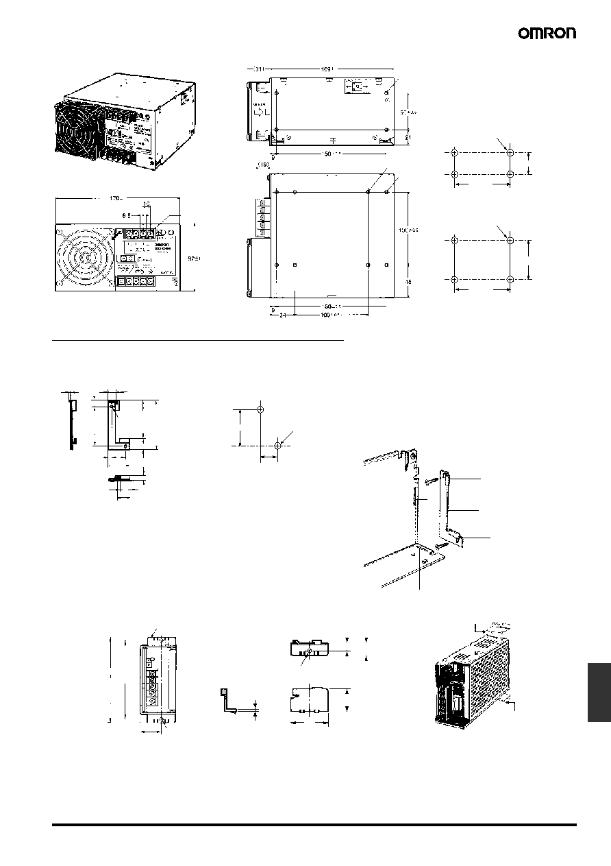
Dimensions
Note: All units are in millimeters unless otherwise indicated.
Open-frame type and covered type have the same dimensions.
I Front-mounting Bracket Type
97
±1
65
±0.5
3.5
161
±1
5
6.5
22
127
±0.5
150.5
±0.5
153
±0.5
3.5
10
28
7
20
20
±0.5
124
±1
3.5
97
±1
65
±0.5
28
3.5
112
±0.5
17.5
21.5
83
±0.5
6.5
5
116
±0.5
6
3.5
90
±1
97
±1
65
±0.5
5
82
±0.5
78
±0.5
6.5
3.5
28
50
±0.5
17.5
15
5
82
±0.5
65
±0.5
78
±0.5
112
±0.5
65
±0.5
116
±0.5
153
±0.5
65
±0.5
150.5
±0.5
35
±1
40
±1
40
±1
12 max.
Two, 3.5 dia.
3.5 dia.
Two, 3.5 dia.
3.5 dia.
12 max.
Two, 3.5 dia.
3.5 dia.
12 max.
S82J-010
@@@ (10 W)
S82J-025
@@@ (25 W)
S82J-050
@@@ (50 W)
Side Mounting
Bottom Mounting
Two, M3
Two, M3
Side Mounting
Bottom Mounting
Two, M3
Two, M3
Mounting Holes
Side Mounting
Bottom Mounting
Two, M3
Two, M3
M3.5 terminal
screw
Two, M3
For track mounting bracket
(4 mm deep max.)
Mounting Holes
(Surface Screw Mounting)
M3.5 terminal
screw
Two, M3
For track mounting bracket
(4 mm deep max.)
Mounting Holes
(Surface Screw Mounting)
M3.5 terminal
screw
Three, M3
For track mounting bracket
(4 mm deep max.)
L-92
Switching Power Supply
S82J
170
±1
4.5
97
±1
65
±0.5
7
162
±0.5
160
±0.5
100
±0.5
15
25
±0.5
4.5
28
±0.5
50
±1
6.5
27.5
15
5
162
±0.5
65
±0.5
160
±0.5
12 max.
Three, M4
4.5 dia.
4.5 dia.
Two, M3
Two, M3
Mounting Holes
Side Mounting
Bottom Mounting
S82J-10024
@
(100 W, 24-V Output)
M3.5 terminal
screw
188
180
±0.5
4.5
97
50
4.5
89
±0.5
35
±0.5
25
±0.5
55
±0.3
100
±0.5
27.5
±0.3
7
±0.3
178
±0.5
3
±0.25
3
±0.25
8.1
9.5
M4 x 8
15
180
±0.5
82
±0.8
178
±0.5
198 (see note)
4 max.
4.5 dia.
4.5 dia.
Mounting holes (on both sides)
Side Mounting
Bottom Mounting
Two, M4
Two, M4
S82J-100
@@@
(100 W, 5-/12-/15-V Output)
S82J-15024
@ (150 W)
Note: Top terminal and connector models
are 188 mm wide.
Three, M4
(6 mm max. deep)
Mounting Holes
(Surface Screw Mounting)
(19)
150
±0.5
50
±0.5
150
±0.5
100
±0.5
S82J-30024
@ (300 W)
Four, M4 holes (depth: 8 max.)
Nine, M4 terminal screws
Side
4 max.
Side Mounting
Bottom Mounting
Four, 4.5 dia.
Four, 4.5 dia.
Eight, M4 holes
(depth: 8 max.
on both sides)
Mounting Holes
(Surface Screw Mounting)
Switching Power Supply
S82J
L-93
Power
Supplies
Dimensions with Mounting Bracket (Provided)
150
±0.5
50
±0.5
150
±0.5
100
±0.5
S82J-60024
@ (600 W)
Four, M4 holes (depth: 8 max. on one side)
Nine, M4 terminal screws
Side Mounting
Bottom Mounting
Four, 4.5 dia.
Four, 4.5 dia.
Mounting Holes
(Surface Screw Mounting)
Eight, M4 holes
(depth: 8 max.
on both sides)
Four, M4 holes
(depth: 8 max.)
(b)
(b)
(a)
(a)
1.5
11
9
60
5
20
31.5
15
20.5
4.7
4.6
11
74
15
±0.2
4.6
60
20
t=1.0
Mounting bracket
Power supply unit
10-/25-/50-/100 (24 V)-W Models
Mounting Holes
Using the Mounting Bracket
Note: The mounting screws are order separately.
Two, M3
Two,
3.5 dia.
Attach the mounting bracket to the panel and
loosely tighten the two screws. Insert the projected
parts of the bracket (b) to the square holes of the
power supply (a). Then securely tighten the screws.
30
±0.5
110
±0.5
38
1.5
6.5
11
t=0.8
23.5
Mounting bracket
120 max.
Two, 5 dia.
100- (5, 12, 15 V) and 150-W Models
Mounting with Brackets
Note: The brackets are for front-mounting.
5 dia.

L-94
Switching Power Supply
S82J
t= 1.6
300-W Models
600-W Models
10 dia.
Two, 5 dia.
Note: To provide ventilation
space, the body will shift
forward by 21.6 mm from
the mounting surface.
Note: To provide ventilation space, the body will shift
forward by 23.6 mm from the mounting surface.

Switching Power Supply
S82J
L-95
Power
Supplies
I DIN Track Mounting Bracket Type
S82J-010
@@@D (10 W)
S82J-025
@@@D (25 W)
9 max. when slided out
9 max. when slided out
7 max.
12 max.
7 max.
12 max.
S82J-050
@@@D (50 W)
9 max. when slided out
9 max. when slided out
S82J-10024
@D
(100 W, 24-V Output)
7 max.
12 max.
7 max.
12 max.

L-96
Switching Power Supply
S82J
I DIN Track Mounting Bracket (Order Separately)
Can be used with 10-W to 150-W Front-mounting Bracket models.
If DIN track mounting is necessary, use a DIN Track Mounting Bracket. Refer to the S82Y DIN Track Mounting Bracket datasheet for details.
I Front-mounting Bracket for S82J-10024@ Power Supply (Order
Separately)
(Unit: mm)
Note: These Front-mounting Brackets cannot be used with S82J 100-W (5, 12, or 15-V) or 150-W models.
9 max. when slided out
S82J-100
@@@D (100 W, 5-/12-/15-V Output)
S82J-15024
@D (150 W)
7 max.
4 max.
Product
Model number
Dimensions
Mounting hole dimensions
Front-mounting
Bracket
S82Y-J10F
180
50
t = 1.6
40
50
Three, 4.5-dia. holes
Three, M4
20
15
15

Switching Power Supply
S82J
L-97
Power
Supplies
Precautions
Mounting
To improve and maintain the reliability of the Power Supply over a
long period of time, adequate consideration must be given to heat
radiation.
The Power Supply is designed to radiate heat by means of natural
air-flow. Therefore, mount the Power Supply so that air flow takes
place around the Power Supply.
When mounting the Power Supply, mounting it to a metal plate is rec-
ommended.
When mounting two or more Power Supplies side-by-side, allow at
least 20 mm spacing between them, as shown in the following illus-
tration.
Forced air-cooling is recommended.
Mounting Methods
The following mounting methods are available.
10-/25-/50-/100 (24 V)-W Models
(A) Side mounting
(B) Bottom mounting
(C) Front mounting (see Accessories)
100 (5, 12, 15 V)/150-/300-/600-W Models
(A) Side mounting (except for 300- and 600-W models)
(B) Bottom mounting (secured with screws from the inside of the
Switching Power Supply) (except for 300- and 600-W models)
(C) Bottom mounting (secured with screws from the back of the
Switching Power Supply)
(D) Front mounting
Front mounting is possible with the mounting brackets provided.
Refer to Dimensions.
Air
Metal plate
20 mm min.
(B)
(A)
(A)
(B)
(C)
Metal plate
Mounting brackets
(provided)

L-98
Switching Power Supply
S82J
Generating Output Voltage (
±)
An output of
± can be generated by using two Power Supplies as
shown below, because the Power Supply produces a floating output.
If operation amplifiers as loads are connected in series, connect a
diode between the positive and negative output terminals of each
Switching Power Supplies as shown in the illustration below. Without
these diodes, the Power Supply may not start when power is turned
on, possibly damaging internal circuits over a period of time.
Use Schottky barrier diodes with a low forward voltage (V
F
). Other
types of diodes will not be effective.
Guidelines for the dielectric strength and current of the diodes are as
follows:
Dielectric strength: At least twice the rated output voltage of the
Power Supply
Forward current: At least twice the rated output
current
No diodes are required for models that allow series operation.
Series Operation
Only models with power ratings of 50/100/150/300/600 W allow
series operation.
As shown in the following diagram, the output voltage from each
Switching Power Supply can be added.
With the S82J-050
@@@@ or S82J-10024@@, if the load is shorted a
reverse voltage may result in the Power Supply causing deterioration
and damage. It is recommended that diodes are connected as
shown in the previous diagram (D
1
, D
2
).
Parallel Operation
Only 300- and 600-W models can be in parallel operation. Do not
operate any other models in parallel. The output of the models in par-
allel operation is a maximum of 80% of the rated output.
Set the parallel operation selector to PARALLEL if the Units are in
parallel operation and make sure that the thickness and the length of
all wires connected to the load are the same to ensure that the wires
will have no voltage drop differences.
Fan Replacement
The service life of the fan is approximately 50,000 hours (at 25
∞C).
The service life varies, however, depending on the ambient tempera-
ture or other surrounding environmental conditions such as dust. As
a preventive maintenance measure, replace the fan within two years
if it is used at an ambient temperature of 40
∞C.
Fans are available as replacements.
Fan Set:
Fan (above), four M4 x 35 sems screws, instruction sheet, and pack-
ing case
Replace the fan as shown in the following illustration.
+V
-V
+V
-V
+V
0 V
-V
INPUT
INPUT
Load
Load
+ V
- V
+ V
- V
D
1
D
2
INPUT
INPUT
Load
Load
Load
+V
-V
+V
-V
D
1
D
2
INPUT
INPUT
Load
Model: S82Y-JFAN
In the interest of product improvement, specifications are subject to change without notice.
ALL DIMENSIONS SHOWN ARE IN MILLIMETERS.
To convert millimeters into inches, multiply by 0.03937. To convert grams into ounces, multiply by 0.03527.
Cat. No. M047-E1-07