Document Outline
- First Page
- Ordering Information
- Specifications
- Engineering Data
- Operation
- Dimensions
- Customized Models
- Molded Terminal Models
- Operation-Indicator Equipped Model
- Contacting Omron

R
2
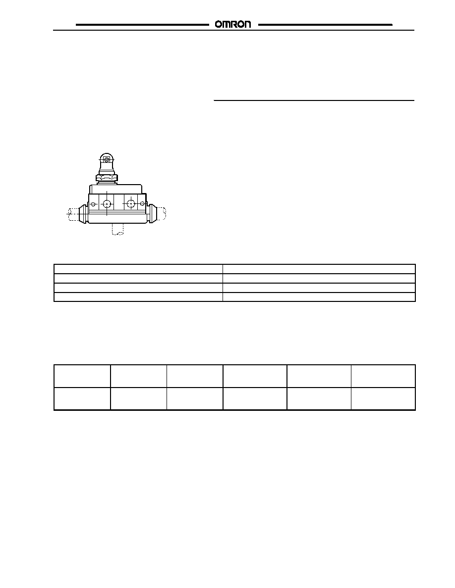
Enclosed Switch
SHL
Subminiature Enclosed Switch
H
Coil-spring switch housed in rigid zinc
diecast alloy boasts long life and high
precision
H
Requires nearly the same operating
force as a conventional precision switch
(0.53 to 0.88 lbf)
H
Molded terminal model is available
H
UL, CSA and/or EN (IEC) approvals
H
Operation-indicator models are
available
Ordering Information
J
LIMIT SWITCHES
Actuator type
Part number
yp
Standard model
Micro voltage/current load model
Plunger
SHL-D55
SHL-D55-01
Panel mount plunger
SHL-Q55
SHL-Q55-01
Panel mount roller plunger
SHL-Q2255
SHL-Q2255-01
Panel mount cross roller plunger
SHL-Q2155
SHL-Q2155-01
Short hinge lever
SHL-W55
SHL-W55-01
Hinge lever
SHL-W155
SHL-W155-01
Short hinge roller lever
SHL-W255
SHL-W255-01
Hinge roller lever
SHL-W2155
SHL-W2155-01
One-way action short hinge roller lever
SHL-W355
SHL-W355-01
One-way action hinge roller lever
SHL-W3155
SHL-W3155-01
Note: For customized models, refer to Molded Terminal Models or Operation-Indicator Equipped Models at the end of this data sheet.

SHL
SHL
3
Specifications
J
RATINGS
General Ratings
Rated voltage
Non-inductive load
Inductive load
Inrush current
Resistive load
Lamp load
(See Note 2.)
Inductive load
(See Note 1.)
Motor load
(See Note 3.)
NC
NO
NC
NO
NC
NO
NC
NO
125 VAC
10 A
1.5 A
3 A
2.5 A
15 A
250 VAC
10 A
1.5 A
2 A
1.5 A
480 VAC
2 A
---
---
---
8 VDC
10 A
2 A
5 A
2 A
14 VDC
10 A
2 A
5 A
2 A
30 VDC
5 A
1.5 A
1.5 A
1.5 A
125 VDC
0.4 A
0.4 A
0.05 A
0.05 A
250 VDC
0.2 A
0.2 A
0.03 A
0.03 A
Note:
Inductive loads have a power factor of 0.4 min. (AC) and a time constant of 7 ms max. (DC).
Lamp load has an inrush current of 10 times the steady-state current.
Motor load has an inrush current of 6 times the steady-state current.
UL/CSA Approved Rating
A300
T�V Rheinland Approved Ratings (EN60947-5-1)
Model
Category and rating
I
the
SHL-j55
AC-15
2 A/125 V
DC-12
2 A/48 V
5 A
4 A
SHL-j5501
AC-14
0.1 A/125 V
DC-12
0.1 A/48 V
0.5 A
0.5 A
SHL-j55L
AC-15
2 A/125 V
5 A
SHL-j5501L
AC-14
0.1 A/125 V
0.5 A
SHL-j55L2
DC-12
2 A/12 V
4 A
SHL-j5501L2
DC-12
0.1 A/12 V
0.5 A
SHL-j55L3
DC-12
2 A/24 V
4 A
SHL-j5501L3
DC-12
0.1 A/24 V
0.5 A
SHL-j55L4
DC-12
2 A/24 V
4 A
SHL-j5501L4
DC-12
0.1 A/24 V
0.5 A
SHL-j55L5
DC-12
2 A/48 V
4 A
SHL-j5501L5
DC-12
0.1 A/48 V
0.5 A

SHL
SHL
4
Micro Voltage/Current Load Model
Rated voltage
Non-inductive load
g
Resistive load
NC
NO
125 VAC
0.1 A
8 VDC
0.1 A
30 VDC
0.1 A
Note: This type is ideal for use in the load range
(Zones 1 through 3) shown below.
V
o
lt
age
(
V
D
C
)
Current (mA)
SHL-j-01
Zone 2
Zone 4
Zone 0
5 mW
Zone 1
0.1 W
0.2 W
0.5 W
Zone 3
J
CHARACTERISTICS
Operating speed
0.1 mm to 50 cm m/s for SHL-Q2255 (0.0039 to 19.68 in/s)
Operating frequency
Mechanical
120 operations/min
p
g
q
y
Electrical
30 operations/min
Insulation resistance
100 M min. (at 500 VDC)
Rated insulation voltage (U
i
)
150 V (IEC947-5-1)
Rated impulse withstand voltage (U
imp
)
2.5 kV (IEC947-5-1)
Switching overvoltage
1,000 VAC, 300 VDC max. (IEC947-5-1)
Short-circuit protective device
10 A fuse (type gG) (IEC269)
Conditional short-circuit current
100 A (IEC947-5-1)
Contact resistance
15 m (initial)
Dielectric strength
1,000 VAC, 50/60 Hz for 1 min between non-continuous terminals
1,500 VAC, 50/60 Hz for 1 min between each terminal and non-current-carrying
metal part
Vibration resistance
Malfunction
10 to 55 Hz, 1.5-mm double amplitude
Shock resistance
Destruction
1,000 m/s
2
(approx. 100G) 3.281 ft/sec
2
Malfunction
300 m/s
2
(approx. 30G) 984 ft/sec
2
Ambient temperature
(See Note.)
Operating
--10�C to 80�C (14�F to 176�F)
Ambient humidity
Operating
95% max.
Operating environment pollution level
Pollution degree 3 (IEC947-5-1)
Life expectancy
Mechanical
10,000,000 operations min. (at rated OT value)
p
y
Electrical
See Engineering Data.
Enclosure ratings
IEC
IP67
Clearance and creepage
Double insulation
Weight
Approx. 62 to 72 g (2.19 to 2.54 oz)
Note: Temperature range below 0�C are based on absence freezing moisture or water.

SHL
SHL
5
J
OPERATING CHARACTERISTICS
Model
SHL-D55
SHL-D55-01
SHL-Q55
SHL-Q55-01
SHL-Q2255
SHL-Q2255-01
SHL-Q2155
SHL-Q2155-01
SHL-W55
SHL-W55-01
OF max.
9.81 N (1,000 gf)
2.21 lbf
9.81 N (1,000 gf)
2.21 lbf
9.81 N (1,000 gf)
2.21 lbf
9.81 N (1,000 gf)
2.21 lbf
3.14 N (320 gf)
2.21 lbf
RF min.
1.96 N (200 gf)
0.44 lbf
1.96 N (200 gf)
0.44 lbf
1.96 N (200 gf)
0.44 lbf
1.96 N (200 gf)
0.44 lbf
0.78 N (80 gf)
0.44 lbf
PT max.
1.5 mm
1.5 mm
1.5 mm
1.5 mm
8 mm
OT min.
2 mm
2 mm
2 mm
2 mm
3 mm
MD max.
0.5 mm
0.5 mm
0.5 mm
0.5 mm
2.5 mm
OP
34�0.8 mm
34�0.8 mm
43�0.8 mm
43�0.8 mm
21.5�1 mm
FP max.
---
---
---
---
29.5 mm
Model
SHL-W155
SHL-W155-01
SHL-W255
SHL-W255-01
SHL-W2155
SHL-W2155-01
SHL-W355
SHL-W355-01
SHL-W3155
SHL-W3155-01
OF max.
2.35 N (240 gf)
0.53 lbf
3.92 N (400 gf)
0.88 lbf
2.55 N (260 gf)
0.57 lbf
3.92 N (400 gf)
0.88 lbf
2.55 N (260 gf)
0.57 lbf
RF min.
0.44 N (45 gf)
0.10 lbf
0.78 N (80 gf)
0.18 lbf
0.49 N (50 gf)
0.11 lbf
0.75 N (80 gf)
0.17 lbf
0.49 N (50 gf)
0.11 lbf
PT max.
13 mm
8 mm
13 mm
8 mm
13 mm
OT min.
5 mm
3 mm
5.5 mm
3 mm
5.5 mm
MD max.
4 mm
2.5 mm
4 mm
2.5 mm
4 mm
OP
21.5�1 mm
33�1 mm
33.5�1 mm
44.5�1 mm
44.5�1 mm
FP max.
34.5 mm
41 mm
46.5 mm
52.5 mm
57.5 mm
Engineering Data
J
ELECTRICAL LIFE EXPECTANCY
Lif
e
ex
pec
t
anc
y
(
x
1
0
oper
at
ions
)
6
Switching current (mA)
Operating frequency:
30 operations/min.
(con = 1)
250 VAC
10
7
5
3
1
0.7
0.5
0.3
0.1

SHL
SHL
6
Operation
J
CONTACT FORM
COM
NC
NO
Dimensions
Unit: mm (inch)
J
LIMIT SWITCHES
SHL-D55, SHL-D55-01
SHL-Q55, SHL-Q55-01
Note: Stainless steel pin plunger
Note: Stainless steel pin plunger
7.8 dia. (See Note.)
Two, 4.2 dia.
holes
Terminal
protective
cover
Rubber seal
Two hexagon nut
(thickness: 2.5,
width: 16)
M14 x 1
15 x 15
M14 x 1
10
(0.39)
17.5
(0.69)
73.5 (2.89)
19
(0.75)
54.6 (2.15)
42.5
45.6 (1.80)
16
(0.63)
10
(0.39)
7.8 dia. (See Note.)
16.5�02
(0.65�0.0079)
SHL-Q2255, SHL-Q2255-01
11 dia. � 4.7 (See Note.)
Note: Sintered stainless alloy roller
17.5
OP
PT
3.5
13
10
(0.39)
17.5
(0.69)
19
(0.75)
16
(0.63)
10
(0.39)
OP
PT
3.5
13
Two hexagon nut
(thickness: 2.5,
width: 16)
M14 x 1
10
(0.39)
17.5
(0.69)
19
(0.75)
16
(0.63)
10
(0.39)
OP
PT
3.5
13
15 x 15
15 x 15
16.5�02
(0.65�0.0079)
Note: Unless otherwise specified, a tolerance of �0.4 mm applies to all dimensions.

SHL
SHL
7
Unit: mm (inch)
SHL-Q2155, SHL-Q2155-01
SHL-W55, SHL-W55-01
SHL-W155, SHL-W155-01
SHL-W255, SHL-W255-01
35R
t = 1 (See Note.)
42.5
6.8
16.5
13
21
(0.83)
24
(0.94)
3.5
16
OP
17.5
FP
15 � 15
Note: Stainless steel lever
53R
6.8
3.5
13
16
OP
FP
17.5
9.5 dia. � 4.8 (See Note.)
31R
6.8
3.5
13
16
OP
FP
Note: Sintered stainless roller
Two hexagon nut
(thickness: 2.5
width: 16)
M14 � 1
11 dia. � 4.7 (See Note.)
15 x 15
16
(0.63)
10
(0.39)
Note: Sintered stainless alloy roller
Note: Stainless steel lever
16.5�02
(0.65�0.0079)
16
(0.63)
10
(0.39)
16
(0.63)
10
(0.39)
16
(0.63)
10
(0.39)
10
(0.39)
17.5
(0.69)
19
(0.75)
3.5
PT
OP
13
M14X1
17.5
(0.69)
16.5�02
(0.65�0.0079)
13
21
(0.83)
24
(0.94)
17.5
(0.69)
16.5�02
(0.65�0.0079)
24
(0.94)
21
(0.83)
17.5
(0.69)
t = 1 (See Note.)
16.5�02
(0.65�0.0079)
Note: Unless otherwise specified, a tolerance of �0.4 mm applies to all dimensions.

SHL
SHL
8
SHL-W2155, SHL-W2155-01
SHL-W355, SHL-W355-01
9.5 dia. � 4.8 (See Note.)
51R
6.8
3.5
13
16
OP
FP
Note: Sintered stainless roller
9.5 dia. � 4.8 (See Note.)
35.5R
90�
6.8
3.5
13
16
OP
FP
Note: Sintered stainless roller
10
(0.39)
16
(0.63)
10
(0.39)
21
(0.83)
24
(0.94)
17.5
(0.69)
21
(0.83)
24
(0.94)
17.5
(0.69)
16.5�02
(0.65�0.0079)
16.5�02
(0.65�0.0079)
16
(0.63)
SHL-W3155, SHL-W3155-01
Mounting Holes
Two, 4.3 dia. or M4 mounting holes
9.5 dia. � 4.8 (See Note.)
90�
52.5R
6.8
3.5
16
OP
FP
15
Note: Sintered stainless roller
10
(0.39)
16
(0.63)
21
(0.83)
24
(0.94)
17.5
(0.69)
16.5�02
(0.65�0.0079)
13
16.5
(0.65)
Note: Unless otherwise specified, a tolerance of �0.4 mm applies to all dimensions.
SHL
SHL
9
Customized Models
Molded Terminal Models
J
ORDERING INFORMATION
Use of the molded terminal model is recommended in locations subject to excessive dust, oil drips, or moisture.
All types of SHL switches can be fabricated into a molded terminal version. In this case, the molded terminal model will have the same
dimensions and operating characteristics as the basic model from which the molded terminal model is fabricated.
ML
MD
MR
Suffix by Location of Lead Outlet
Location of lead outlet
Part number
Right-hand
SHL-j
j
j
j
-MR
Left-hand
SHL-j
j
j
j
-ML
Underside
SHL-j
j
j
j
-MD
Note: Three leads (COM, NO, and NC) are provided for terminal connections.
Example:
Basic type: SHL-Q2255
Location of lead outlet: Right-hand
When placing your order for the above switch, specify the model number as SHL-Q2255-MR
Lead Supplies
Leads
Nominal
cross-sectional
area
No. of
conductors/cond.
dia.
Finished outside
diameter
Terminal connections
Standard length
VCTF (Vinyl
cabtyre cable)
0.75 mm
2
30/0.18 mm
(0.007 in) dia.
3-core 7.2 mm
(0.28 in) dia.
Black: COM
White: NO
Red: NC
3 m (118.11 in)
SHL
SHL
10
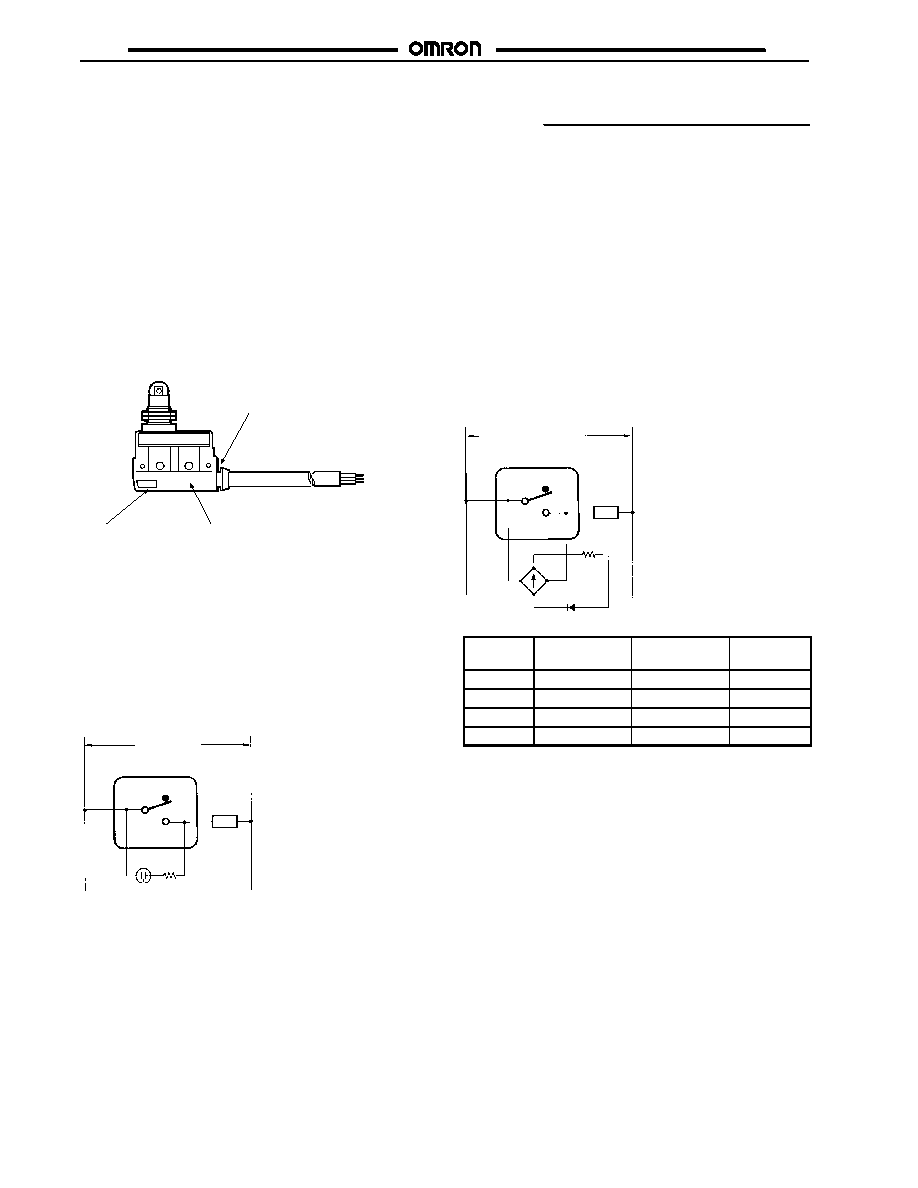
Operation-Indicator Equipped Model
J
ORDERING INFORMATION
UL, CSA and/or EN (IEC) approved models are available.
The molded terminal model may be equipped with an operation
indicator (neon lamp or LED) upon request to facilitate
maintenance and inspection.
The operation indicator is designed to illuminate when the switch is
not operating. (Because of the molded terminal model, any change
to the switch wiring cannot be made.)
J
AC OPERATION
A neon lamp indicator is provided.
The operating voltage is 90 to 250 VAC.
Matte finish
Transparent terminal
protection cover
Neon lamp
Operating characteristics are the same as the basic model from
which the operation indicator equipped model is fabricated.
Dimension are the same as the standard model.
Example:
Basic type: SHL-Q2255-01MR
When placing your order for the molded terminal model with a
neon lamp operation indicator, specify the model number as
SHL-Q2255-01LMR.
Internal Circuit
Load
Neon
lamp
Built-in switch
R = 240 k
Power supply
J
DC OPERATION
LED indicator is provided.
As a rectifier stack is incorporated into the unit and no
directionality exists for connection of + and --, this type can also
be operated on AC.
Voltage ratings of LED indicators are as shown in the table
below.
The switch case has a protrusion to facilitate visual confirmation
of LED indicator.
Example:
Basic type: SHL-Q2255-01MR
When placing your order for the molded terminal with an LED
indicator rated at 12 V, specify the model number as
SHL-Q2255-01L2MR.
Contact Circuit
Load
LED
Resistor
Built-in switch
Power supply
Type
Voltage rating
Lamp current
Internal
resistance
L2
12 V
Approx. 2.4 mA
4.2 k
L3
24 V
Approx. 2 mA
10 k
L4
24 V
Approx. 1.2 mA
18 k
L5
48 V
Approx. 2.1 mA
22 k

SHL
SHL
Cat. No. CEDSAX4 11/01 Specifications subject to change without notice. Printed in U.S.A.
OMRON ELECTRONICS LLC
One East Commerce Drive
Schaumburg, IL 60173
NOTE: DIMENSIONS SHOWN ARE IN MILLIMETERS. To convert millimeters to inches divide by 25.4.
1-800-55-OMRON
OMRON CANADA, INC.
885 Milner Avenue
Scarborough, Ontario M1B 5V8
416-286-6465
R
OMRON ON--LINE
Global -- http://www.omron.com
USA -- http://www.omron.com/oei
Canada -- http://www.omron.com/oci